2AB8I-RR4Transceiver for Utility Meters
Next Meters Global, LLC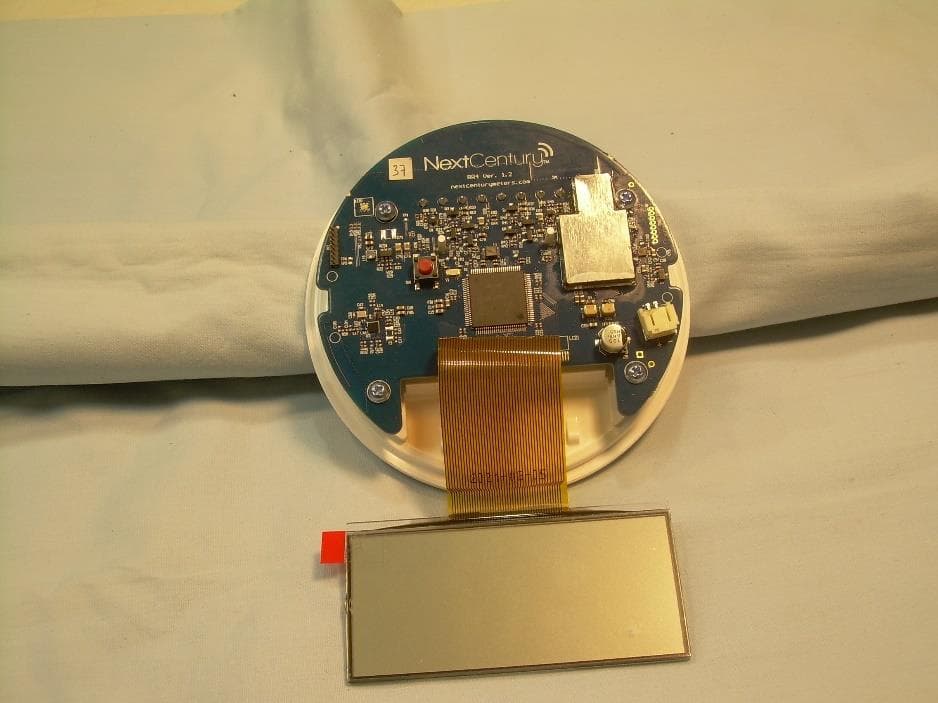
Click to zoom
Application Details
- Equipment Class
- DTS - Digital Transmission System
- Date of Grant
- Apr 26, 2021
- Application Purpose
- Original Equipment
- Date of Application
- Apr 26, 2021
- Equipment Note
- Transceiver for Utility Meters
- Frequency Range
- 2402.00000000 - 2480.00000000
- Company
- Next Meters Global, LLC
- Country
- United States
Documents & Files
Document Text
Text extracted from the exhibit documents filed with the FCC. Open a document above to read the original.
Users Manual
[email protected] www.nextcenturymeters.com V. 091520 RR4-TR Remote Reader With Integrated NextCentury Transceiver (Radio) Operation and Installation Guide 1| Product Overview The NextCentury RR4-TR Remote Reader is an advanced meter reading solution which provides a high visibility remote display of one or two utility meters. The Remote Reader is an NTEP certified remote display for water, electric, and gas applications. The Remote Reader has an attractive consumer design, making it an ideal solution for apartment and remote metering. The utility and unit of measure are clearly displayed, ensuring an accurate interpretation of the read. In addition to displaying the meter read, the RR4-TR Remote Reader operates as a wireless transceiver end-point to transmit meter read data to the NextCentury cloud platform. The Remote Reader utilizes Dual Meter+™ technology, making this single model compatible with virtually all modern encoded and pulse-output utility meters, including water, electric, gas, run-time, and thermal meter models. 2| Technical Specifications 2.1 – Certifications FCC: 2AB8I-RR4 IC: 20949-RR4 NTEP: 20-012 IP-Rating: Tested to IP65 2.2 – Wireless ● NextCentury two-way Communications Radio ● 902-928 MHz Unlicensed Band 2.3 – Dual Meter+™ ● Any combination of two encoded or pulse-output meters ● Pulse output configuration capable 2.4 – Configuration Methods ● A Cloud-connected GW301 Gateway or a DC301 Direct Connect device (sold separately) is required to change the RR4-TR configuration. ● Pre-programming available. 2.5 – Battery ● Preinstalled, field replaceable ER18505 ● Up to *10-year battery life *Note: 10-year average battery life calculated and tested at typical operating temperatures between 70ºF-90ºF. Battery life may be reduced when operated outside of this range. 2.6 – Dimensions: ● Display unit and mounting plate: 5.7” x 4.6” x 1.7” (145mm x 117mm x 44mm) ● Mounting holes center-to-center: 3.5” (88.4 mm) ● Compatible with a standard single gang wall-box 2.7 – Operation Environment: ● -20°C to 60°C (-4°F to 140°F ) ● Should be installed in an indoor, dry environment ● Outdoor Ratings: (coming soon) 3| Meter Compatibility The NextCentury Remote Reader integrates Dual Meter+™ technology, allowing for compatibility with virtually all modern meter outputs. 3.1 – Pulse Output Meters ● Passive pulse sensing (including reed switch, solid- state relay, contact relay, open-drain types) ● Active voltage sensing (max. 16 VDC) 3.2 – Encoded Output Meters ● Neptune (Including ProRead, ECoder, and ProCoder register models) ● Sensus UI-1203 (Includes most meter models from Sensus, Hersey, Mueller, Master Meter, Badger, Kamstrup, Elster, Metron-Farnier, and Zenner) ● Elster/AMCO K-Frame (Includes most meter models from Elster, AMCO, ABB and Kent) 4| Packaging Contents [email protected] www.nextcenturymeters.com V. 091520 A - RR4-TR Remote Reader E - Box Mount Screws #6-32 B - Mounting Plate F - Wire Security Assembly C - Sheetrock Anchors G - Security Seal Tabs D - Wall Mount Screws #6-20 5| In-Field Installation 5.1 – Detach from Mounting Plate ● Pull down the security tab, the Remote Reader can then be pulled off the mounting plate. ● Slide the security tab back to its original position when installation is complete. DO NOT open the Remote Reader unless replacement of the battery is necessary (approx. every 10 years). It is not necessary to disassemble/open a Remote Reader during installation. 5.2 – Mounting Plate Installation ● Hold the mounting plate at the desired height and use the integrated level to straighten. ● Use a pencil to mark holes for pre-drilling ● Pre-drill using a 7/32” (5.5mm) drill bit ● Insert plastic anchors and attach the mounting plate with a PH-1 screwdriver and the two screws (fig. 4-D). 5.3 – Wall Box (optional) ● Pass the meter wire(s) through the mounting plate access holes ● Use a PH-1 screwdriver and the two screws (fig. 4-E) to attach the mounting plate 5.4 – Meter Wiring The Remote Reader can be connected to one or two meters. Use Meter 1 (left 3 terminals) and Meter 2 (right 3 terminals) to connect meters to the Remote Reader’s mounting plate. ● Strip meter wire ends to 3/16” (5 mm) ● Insert the wire ends into the terminal block and tighten securely using a PH-1 screwdriver 5.5 – Meter Wiring Diagram 5.6 – Tamper Evident Seal ● The Security Tab Seal (figure 4-F) or Security Wire Seal (figure 4-G) can be used according to your installation specifications. 6| Configuration Programming Methods 6.1 – Cloud Configuration ● Performed using the NextCentury Website or Mobile App ● Use this configuration method when a Cloud- connected Gateway and Repeaters have already been installed. [email protected] www.nextcenturymeters.com V. 091520 6.2 – Direct Connect with DC301 Configuration ● Performed using the DC301 Direct Connect Programmer (available separately). ● Use this configuration method when a cloud- connected Gateway is not yet available. ● May also be used for advanced troubleshooting and diagnostics. 7| Setting the Configuration 7.1 – Configuration Changes ● The RR4-TR is capable of accepting new configuration parameters during any wireless check-in. 7.2 – Initiating Wireless Check-In ● A wireless check-in can be initiated when the RR4-TR is snapped onto its mounting plate. ● Subsequent check-ins can be initiated using a magnet within the magnetic activation zone. 7.3 – Magnetic Activation Zone A wireless check-in is initiated when a magnet is moved past the activation zone highlighted in this figure. 7.4 – LED Indicator The LED indicator provides feedback to easily check the status of the RR4-TR. Checking In (red) Meter 1 Pulse (blue) Response Received (green) Meter 2 Pulse (purple) 8| LCD Display 8.1 – LCD Display Example 8.2 – Meter Display Views The RR4-TR will rotate through the following views at a 5-10 second interval (as applicable to its configuration). Meter 1 • Meter read, utility, unit of measure • Meter read,…
Text truncated - open the document above for the full version.
External Photos
313 West 12800 South, Suite 311, Draper, UT 84020 • (801) 260-4040 RR4_ExtPho.docx Page 1 of 4 PROPRIETARY External Photographs Photograph 1 – Front View of the EUT Photograph 2 – Side 1 View 313 West 12800 South, Suite 311, Draper, UT 84020 • (801) 260-4040 RR4_ExtPho.docx Page 2 of 4 PROPRIETARY Photograph 3 – Back View of the EUT Photograph 4 – Side 2 View 313 West 12800 South, Suite 311, Draper, UT 84020 • (801) 260-4040 RR4_ExtPho.docx Page 3 of 4 PROPRIETARY Photograph 5 – Side 3 View Photograph 6 – Side 4 View 313 West 12800 South, Suite 311, Draper, UT 84020 • (801) 260-4040 RR4_ExtPho.docx Page 4 of 4 PROPRIETARY Photograph 7 – PCB Placement View
Internal Photos
313 West 12800 South, Suite 311, Draper, UT 84020 • (801) 260-4040 RR4_IntPho.docx Page 1 of 5 PROPRIETARY Internal Photographs Photograph 1 – Front View of the Device RF Shield 313 West 12800 South, Suite 311, Draper, UT 84020 • (801) 260-4040 RR4_IntPho.docx Page 2 of 5 PROPRIETARY Photograph 2 – Back View of the Device 313 West 12800 South, Suite 311, Draper, UT 84020 • (801) 260-4040 RR4_IntPho.docx Page 3 of 5 PROPRIETARY Photograph 3 – View of Circuitry Under the RF Shield 313 West 12800 South, Suite 311, Draper, UT 84020 • (801) 260-4040 RR4_IntPho.docx Page 4 of 5 PROPRIETARY Photograph 4 – 900MHz Trace Antenna Trace Antenna 313 West 12800 South, Suite 311, Draper, UT 84020 • (801) 260-4040 RR4_IntPho.docx Page 5 of 5 PROPRIETARY Photograph 5 – BLE Trace Antenna Trace Antenna
RF Exposure Info
313 West 12800 South, Suite 311, Draper, UT 84020 • (801) 260-4040 RR4_MPE.docx Page 1 of 2 PROPRIETARY 47 C.F.R. Part 1, Subpart I, Section 1.1310 47 C.F.R. Part 2, Subpart J, Section 2.1091 Maximum Permissible Exposure Calculations For FCC ID: 2AB8I-RR4 EUT Device Category = General Population/Uncontrolled Exposure EUT consists of two ISM band radio transmitting. One operating over a range of: 2402 MHz to 2480 MHz, and one operating over a range of 910.2 MHz to 920 MHz. MPE Summary: According subpart 1.1307 (b)(1) and 2.1091 systems operating under the provisions of this section shall be operated in a manner that ensures the public is not exposed to RF energy level in excess of the communication guidelines. Limits for General Population/Uncontrolled Exposure Limits for General Population/Uncontrolled Exposure Frequency Range (MHz) Electric Field Strength (V/m) Magnetic Field Strength (A/m) Power Density (mW/cm2) Averaging Time (Minutes) 0.3-1.34 614 1.63 *(100) 30 1.34-30 824/f 2.19/f *(180/f2) 30 30-300 27.5 0.073 0.2 30 300-1500 / / f/1500 30 1500-100,000 / / 1.0 30 f = frequency in MHz; * = Plane-wave equivalent power density Calculated Formulary: Predication of MPE limit at a given distance S = power density (in appropriate units, e.g. mW/cm 2 ) R = distance to the center of radiation of the antenna (appropriate units, e.g., cm) PG = EIRP 313 West 12800 South, Suite 311, Draper, UT 84020 • (801) 260-4040 RR4_MPE.docx Page 2 of 2 PROPRIETARY MPE and Limit are calculated for this device as follows: 2.402 GHz to 2.48 GHz Frequency Band BLE Transceiver Freq Output Power (dBm) Max Antenna Gain (dBi) Max EIRP (dBm) Max EIRP (mW) Power Density at 20 cm (mW/cm2) Limit (mW) Margin (mW) 2402 4.07 0.0 4.07 2.55 0.001 1.000 0.999 2440 4.69 0.0 4.69 2.95 0.001 1.000 0.999 2480 5.78 0.0 5.78 3.79 0.001 1.000 0.999 910.2 MHz to 920.0 MHz Frequency Band Freq Output Power (dBm) Max Antenna Gain (dBi) Max EIRP (dBm) Max EIRP (mW) Power Density at 20 cm (mW/cm2) Limit (mW) Margin (mW) 910.2 24.67 0.0 24.67 293.0 0.058 0.607 0.549 915.0 24.16 0.0 24.16 260.6 0.052 0.610 0.558 920.0 23.73 0.0 23.73 236.0 0.047 0.613 0.566 Result: There are two transceivers in the device. They will never transmit at the same time as only one radio is configured for use in each installation. The device meets FCC MPE limit at 20 cm for General Population/Uncontrolled Exposure as specified in 47 CRF §1.1310 and §2.1091.
Test Report
313 West 12800 South, Suite 311 Draper, UT 84020 (801) 260-4040 Test Report Certification FCC ID 2AB8I-RR4 Equipment Under Test RR4 Test Report Serial No V057053_01 Dates of Test March 4 and 18, 2021 Report Issue Date March 23, 2021 Test Specifications: Applicant: FCC Part 15, Subpart C Next Century Submetering Systems, LLC P.O. Box 360 Tybee Island, GA 31328 U.S.A. 313 West 12800 South, Suite 311, Draper, UT 84020 • (801) 260-4040 V057053_01_RR4_FCC_Sub_C_BLE.docx Page 2 of 35 PROPRIETARY Certification of Engineering Report This report has been prepared by VPI Laboratories, Inc. to document compliance of the device described below with the requirements of Federal Communications Commission (FCC) Part 15, Subpart C. This report may be reproduced in full. Partial reproduction of this report may only be made with the written consent of the laboratory. The results in this report apply only to the sample tested. Applicant Next Century Submetering Systems, LLC Manufacturer Next Century Submetering Systems, LLC Brand Name Next Century Model Number RR4 FCC ID 2AB8I-RR4 On this 23 rd day of March 2021, I, individually and for VPI Laboratories, Inc., certify that the statements made in this engineering report are true, complete, and correct to the best of my knowledge, and are made in good faith. Although NVLAP has accredited the VPI Laboratories, Inc. EMC testing facilities, this report must not be used to claim product certification, approval, or endorsement by NVLAP, NIST, or any agency of the federal government. VPI Laboratories, Inc. Tested by: Norman P. Hansen Reviewed by: Benjamin N. Antczak 313 West 12800 South, Suite 311, Draper, UT 84020 • (801) 260-4040 V057053_01_RR4_FCC_Sub_C_BLE.docx Page 3 of 35 PROPRIETARY Revision History Revision Description Date 01 Original Report Release March 23, 2021 313 West 12800 South, Suite 311, Draper, UT 84020 • (801) 260-4040 V057053_01_RR4_FCC_Sub_C_BLE.docx Page 4 of 35 PROPRIETARY Table of Contents 1 Client Information ................................................................................................................................. 5 1.1 Applicant ....................................................................................................................................... 5 1.2 Manufacturer ................................................................................................................................. 5 2 Equipment Under Test (EUT) ............................................................................................................... 6 2.1 Identification of EUT .................................................................................................................... 6 2.2 Description of EUT ....................................................................................................................... 6 2.3 EUT and Support Equipment ........................................................................................................ 6 2.4 Interface Ports on EUT ................................................................................................................. 7 2.5 Modification Incorporated/Special Accessories on EUT .............................................................. 7 2.6 Deviation from Test Standard ....................................................................................................... 7 3 Test Specification, Methods and Procedures ........................................................................................ 8 3.1 Test Specification .......................................................................................................................... 8 3.2 Methods & Procedures .................................................................................................................. 8 3.3 Test Procedure ............................................................................................................................ 12 4 Operation of EUT During Testing ...................................................................................................... 13 4.1 Operating Environment ............................................................................................................... 13 4.2 Operating Modes ......................................................................................................................... 13 4.3 EUT Exercise Software ............................................................................................................... 13 5 Summary of Test Results .................................................................................................................... 14 5.1 FCC Part 15, Subpart C .............................................................................................................. 14 5.2 Result .......................................................................................................................................... 14 6 Measurements, Examinations and Derived Results ............................................................................ 15 6.1 General Comments ...................................................................................................................... 15 6.2 Test Results ................................................................................................................................. 15 7 Test Procedures and Test Equipment .................................................................................................. 24 7.1 Radiated Emissions ..................................................................................................................... 24 7.2 Equipment Calibration ................................................................................................................ 25 7.3 Measurement Uncertainty ........................................................................................................... 26 8 Photographs .....................…
Text truncated - open the document above for the full version.
Test Setup Photos
313 West 12800 South, Suite 311, Draper, UT 84020 • (801) 260-4040 RR4_Tsup.docx Page 1 of 4 PROPRIETARY Test Set Up Photographs Radiated Photograph 1: Front View Radiated Emissions, Below 1000 MHz Worst Case Configuration Photograph 2: Back View Radiated Emissions, Below 1000 MHz Worst Case Configuration 313 West 12800 South, Suite 311, Draper, UT 84020 • (801) 260-4040 RR4_Tsup.docx Page 2 of 4 PROPRIETARY Photograph 3: Front View Radiated Emissions Worst Case – Above 1000 MHz Configuration Photograph 44: Back View Radiated Emissions Worst Case – Above 1000 MHz Configuration 313 West 12800 South, Suite 311, Draper, UT 84020 • (801) 260-4040 RR4_Tsup.docx Page 3 of 4 PROPRIETARY Reference Test Set Up Photographs Photograph 5: Reference Photo of Test Setup for Emissions Below 30 MHz Photograph 6: Reference Photo of Test Setup for Emissions From 30 MHz to 1000 MHz 313 West 12800 South, Suite 311, Draper, UT 84020 • (801) 260-4040 RR4_Tsup.docx Page 4 of 4 PROPRIETARY Photograph 7: Reference Photo of Test Setup for Emissions Above 1000 MHz
Contact Information
Applicant
Brett Jepsen(Executive Engineer)
Test Firm
VPI TechnologyJason Stewart
[email protected]801-495-2310
Technical Specifications
| # | Rule Parts | Frequency Range | Power Output |
|---|---|---|---|
| 1 | 15C | 2.40 GHz - 2.48 GHz | 3.79 mW |
Other Applications from Next Meters Global, LLC
2AB8I-RE4
Jul 29, 2021Transceiver for Utility Meters
Equipment Class
DTS - Digital Transmission System
2AB8I-TR4
Feb 24, 2021Transceiver for Utility Meters
Equipment Class
DSS - Part 15 Spread Spectrum Transmitter
2AB8I-DC301
May 14, 2020Wireless Programming Tool
Equipment Class
DTS - Digital Transmission System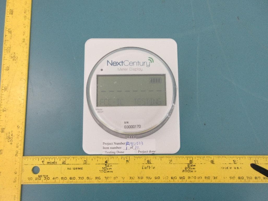
2AB8I-RR301
Feb 05, 2020Remote Reader
Equipment Class
DSS - Part 15 Spread Spectrum Transmitter