2ABBZ-RF-CHWDSCDoor/Window Sensors for Security System
Cinch Systems, Inc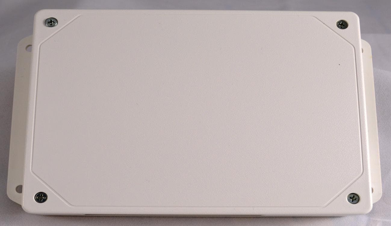
Click to zoom
Application Details
- Equipment Class
- DSC - Part 15 Security/Remote Control Transmitter
- Date of Grant
- Jul 20, 2015
- Application Purpose
- Original Equipment
- Date of Application
- Jul 20, 2015
- Equipment Note
- Door/Window Sensors for Security System
- Frequency Range
- 433.91500000 - 433.91500000
- Company
- Cinch Systems, Inc
- Country
- United States
Documents & Files
Document Text
Text extracted from the exhibit documents filed with the FCC. Open a document above to read the original.
Users Manual
Hardwire to Wireless Converter RF-CHW-ITI-8 - 433 MHz Description: The RF-CHW-ITI-8 module allows the conversion of hardwire security sensors to Qolsys wireless tech- nology. The module is a cost effective way of up- grading a security system and using existing hard- wire security zones. The module supports both magnetic contacts and powered zones (12VDC) as motion detectors (power required from second source). The module uses the existing EOL resistors so no re-wiring or changing out EOL’s is required. Installation: Mounting location - if retrofitting an existing hard- wire control panel, mount the module at that loca- tion to minimize splicing wires. Note: if possible use the existing enclosure to house the module and battery, remember the antenna on the module must protrude from any metal enclo- sure. Wiring (see wiring diagram) Power transformer - 2 conductor Zone wiring - from existing control panel Backup battery Note: use 22 AGW minimum Note: Make sure EOL resistors remain in place for all zones RF-CHW-ITI-8 - 433MHz Programming: The RF-CHW-ITI-8 module is a wireless device that enrolls into the Qolsys control panel. The module has a unique ID # that the control panel responds to for tamper and low battery conditions. Also each zone is assigned it’s own ID# for reporting purposes. Module setup: Clear Memory: Disconnect all power battery and transformer, press and hold the memory reset button while applying power The LED’s will flash indicating memory reset Power module by plugging in the transformer and connecting backup battery if required Notes: Polarity on transformer marked as dashed line on positive wire Make sure all input EOL’s are properly wired for N/O (parallel) or N/C (series) configuration All zones must be wired with an EOL resistor, either a 3K ohm from the accessory kit or the existing resistor from the previous system Place all zones in normal non alarm condition Enrolling zones into the Qolsys panel: Enroll EOL’s and zones Put the module in Learn Zone mode by pressing the EOL Learn button and holding for 5 seconds, all LEDs will flash, this process also learns in all of the EOL’s Enter system programming on the Qolsys panel Settings menu, enter user code Installation menu, Security Sensors, Auto Learn Sensor Enroll zones by activating the zone, the Qolsys panel will respond with each successful wireless activation and required zone type and name selection before the next zone is tripped. After all zones are enrolled press the EOL Learn Button to exit program mode on the module, all LED’s will go out Note: Learning zones cannot be done if the EOL Cali- bration LED is Flashing or Off Testing On the Qolsys panel enter Settings, enter user code Press System Test, Sensor Test Activate all zones on the module and verify they Pass FCC label statement: “This device complies with part 15 of the FCC Rules. Operation is subject to the following two conditions: (1) This device may not cause harmful interfer- ence, and (2) this device must accept any interference received, including interference that may cause undesired operation.” “Note: This equipment has been tested and found to comply with the limits for a Class B digital device, pursuant to part 15 of the FCC Rules. These limits are designed to provide reasonable protection against harmful interference in a residential installation. This equipment generates, uses and can radiate radio frequency energy and, if not installed and used in accordance with the instructions, may cause harmful interference to radio communications. However, there is no guarantee that interference will not occur in a particu- lar installation. If this equipment does cause harmful interference to radio or television reception, which can be determined by turning the equipment off and on, the user is encouraged to try to correct the interference by one or more of the following measures: —Reorient or relocate the receiving antenna. —Increase the separation between the equipment and receiver. —Connect the equipment into an outlet on a circuit different from that to which the receiver is connected. —Consult the dealer or an experienced radio/TV technician for help.” “Changes or modifications not expressly approved by the party responsible for compliance could void the user's authority to operate the equipment” “RF Exposure Guidance: This equipment complies with FCC radiation expo- sure limits set forth for an uncontrolled environment. This equipment should be installed and operated with a minimum distance of 1.5cm between the radiator and persons. This transmitter must not be co-located or operating in conjunction with any other antenna or transmitter, except in accordance with FCC multi-transmitter product procedures.” Specifications: Input Voltage: 16.0VDC plug-in transformer Backup Battery: 12VDC 5Ah max (optional) Dimensions: 5.5” X 3.5” Operating Temperature: 32 to 122F (0 to 50C) Humidity: 95% RH Max EOL Supervision: 1K to 10K Ohm Input Zones: 8 (if used must have EOL resistor) Zone Type—N/O or N/C compatible Auxiliary Voltage Output: 12VDC @ 500mA Cinch Stick Port: Field upgradable firmware Relay Contact—60VDC/1A Max, used to drive siren or other device Notes: Used zones must have an EOL installed Make sure when installed the antenna is free of all metal obstructions Module Switches: EOL Learn - used to calibrate EOL resistors and enter program mode Memory Reset - clears memory of module Module LED’s Processor - flashes during normal operation RF Xmit - flashes when an RF transmission is sent EOL Cal: On - calibration required, Off - calibration complete Zones: Flash twice when ready to enroll, On - when enrolled in programming and when tripped, Off - when zone in normal condition Metal Enclosure Plastic Enclosure
Users Manual
Hardwire to Wireless Converter RF-CHW-ITI-16 - 433 MHZ Description: The RF-CHW-ITI-16 module allows the conversion of hardwire security sensors to Qolsys wireless technology. The module is a cost effective way of upgrading a security system and using existing hardwire security zones. The module supports both magnetic contacts and powered zones (12VDC) as motion detectors. The module uses the existing EOL resistors so no re-wiring or changing out EOL’s is required. Installation: Mounting location - if retrofitting an existing hard- wire control panel, mount the module at that loca- tion to minimize splicing wires. Note: if possible use the existing enclosure to house the module and battery, remember the antenna on the module must protrude from any metal enclo- sure. Wiring (see wiring diagram) Power transformer - 2 conductor Zone wiring - from existing control panel Zone power Siren extension Backup battery Note: use 22 AGW minimum Note: Make sure EOL resistors remain in place for all zones RF-CHW-ITI-16 - 433 MHz Programming: The RF-CHW-ITI-16 module is a wireless device that enrolls into the Qolsys control panel. The module has a unique ID # that the control panel responds to for tamper and low battery conditions. Also each zone is assigned it’s own ID# for reporting purposes. Module setup: Clear Memory: Disconnect all power battery and transformer, press and hold the memory reset button while applying power The LED’s will flash indicating memory reset Power module by plugging in the transformer and connecting backup battery if required Notes: Polarity on transformer marked as dashed line on positive wire Make sure all input EOL’s are properly wired for N/O (parallel) or N/C (series) configuration All zones must be wired with an EOL resistor, either a 3K ohm from the accessory kit or the existing resistor from the previous system Place all zones in normal non alarm condition Enrolling module and zones into the Qolsys panel - if the module tamper and battery supervision are re- quired the module must be enrolled into the control panel (this step not required if no backup battery or tamper are used) Enroll module, EOL’s and zones Put the module in Learn Zone mode by pressing the EOL Learn button and holding for 5 seconds, all LEDs will flash, this process also learns in all of the EOL’s Enter system programming on the Qolsys panel Settings menu, enter user code Installation menu, Security Sensors, Auto Learn Sensor To enroll the module trip the tamper zone The Qolsys panel will indicate a sensor has been detected and require pressing the control panel OK to add the sensor The Qolsys panel will display sensor characteris- tics that can be changed if required, when com- plete press Add New The Qolsys panel returns to the Auto Learn Sen- sor and waits for the next sensor to be activated Continue enrolling zones by activating the zone, the Qolsys panel will respond with each success- ful wireless activation and required zone type and name selection before the next zone is tripped. After all zones are enrolled press the EOL Learn Button to exit program mode on the module, all LED’s will go out Note: Learning zones cannot be done if the EOL Cali- bration LED is Flashing or Off Testing On the Qolsys panel enter Settings, enter user code Press System Test, Sensor Test Activate all zones on the module and verify they Pass FCC label statement: “This device complies with part 15 of the FCC Rules. Operation is subject to the following two conditions: (1) This device may not cause harmful interfer- ence, and (2) this device must accept any interference received, including interference that may cause undesired operation.” “Note: This equipment has been tested and found to comply with the limits for a Class B digital device, pursuant to part 15 of the FCC Rules. These limits are designed to provide reasonable protection against harmful interference in a residential installation. This equipment generates, uses and can radiate radio frequency energy and, if not installed and used in accordance with the instructions, may cause harmful interference to radio communications. However, there is no guarantee that interference will not occur in a particu- lar installation. If this equipment does cause harmful interference to radio or television reception, which can be determined by turning the equipment off and on, the user is encouraged to try to correct the interference by one or more of the following measures: —Reorient or relocate the receiving antenna. —Increase the separation between the equipment and receiver. —Connect the equipment into an outlet on a circuit different from that to which the receiver is connected. —Consult the dealer or an experienced radio/TV technician for help.” “Changes or modifications not expressly approved by the party responsible for compliance could void the user's authority to operate the equipment” “RF Exposure Guidance: This equipment complies with FCC radiation expo- sure limits set forth for an uncontrolled environment. This equipment should be installed and operated with a minimum distance of 1.5cm between the radiator and persons. This transmitter must not be co-located or operating in conjunction with any other antenna or transmitter, except in accordance with FCC multi-transmitter product procedures.” Specifications: Input Voltage: 16.0VDC plug-in transformer Backup Battery: 12VDC 5Ah max (optional) Dimensions: 5.5” X 3.5” Operating Temperature: 32 to 122F (0 to 50C) Humidity: 95% RH Max EOL Supervision: 1K to 10K Ohm Input Zones: 16 (if used must have EOL resistor) Zone Type—N/O or N/C compatible Auxiliary Voltage Output: 12VDC @ 500mA Cinch Stick Port: Field upgradable firmware Tamper Zone: Separate zone input for tamper Relay Contact—60VDC/1A Max, used to drive siren or other device Notes: Used zones must have an EOL installed If a backup battery is installed, the mod- ule must be enrolled into the Qolsys panel Make sure w…
Text truncated - open the document above for the full version.
External Photos
External Photos Front View Back View Top View Bottom view Side view Alternate Side View Dimensions 5.5 inches 3.5 inches
External Photos
External Photos Front View Back View Top View Bottom view Side view Alternate Side View Dimensions 5.5 inches 3.5 inches
ID Label/Location Info
Label Samples Labels are UL Listed and utilize permanent adhesive. Tyco P/N WP-040040-10-9 Applied by hand
Internal Photos
Model: RF-CHW-ITI-8 Internal Photo Top View Bottom view Side view Alternative side view Front View Back view
Internal Photos
Model: RF-CHW-ITI-16 Internal photos top view Back View Side view Alternative side view Front view Back view
RF Exposure Info
Scanned by CamScanner
Test Report
TÜV SÜD AMERICA INC 1775 Old Hwy 8 NW, Suite 104 New Brighton MN 55112-1891 Tel: (651) 638-0297 Fax: (651) 638-0298 Rev. 113006 TEST REPORT FCC Part 15 Subpart C Section 15.231 IC RSS-210 Issue 8, Amendment 1 IC RSS-Gen Issue 4 MANUFACTURER'S NAME Cinch Systems Inc 12075 43rd Street NE Suite 300 St Michael MN 55376 USA PRODUCT NAME(S) Hardwire Converter MODEL NUMBER(S) TESTED RF-CHW-DSC-16 SERIAL NUMBER(S) TESTED 123456 PRODUCT DESCRIPTION Hardwire Converter with 433.92 MHz transmitter TEST REPORT NUMBER NC72106641.1 Rev A TEST DATE(S) 27 May 2015 TÜV SÜD America Inc, as an independent testing laboratory, declares that the equipment tested as specified above conforms to the applicable EMC requirements of FCC Part 15 Subpart C Sections 15.231 “Periodic operation in the band 40.66–40.70 MHz and above 70 MHz.” and 15.207 “Conducted limits.”, Industry Canada RSS-210 Issue 8 Amendment 1 “Licence-exempt Radio Apparatus (All Frequency Bands): Category I Equipment” and RSS-Gen Issue 4 “General Requirements and Information for the Certification of Radio Apparatus”. It is the manufacturer's responsibility to assure that additional production units of this model are manufactured with identical electrical and mechanical characteristics. Any modifications necessary for compliance made during testing on the above mentioned date(s) must be implemented in all production units for compliance to be maintained. Issue Date: 23 July 2015 Joel T Schneider Greg Jakubowski Senior EMC Engineer Senior EMC Technician Not Transferable FCC ID: 2ABBZ-RF-CHWDSC IC: 11817A-RFCHWDSC TÜV SÜD AMERICA INC 1775 Old Hwy 8 NW, Suite 104 New Brighton MN 55112-1891 Tel: (651) 638-0297 Fax: (651) 638-0298 Rev. 113006 EMC TEST REPORT Test Report No. NC72106641.1 Rev A Date of issue: 23 July 2015 Product Names Hardwire Converter Model(s) Tested RF-CHW-DSC-16 Serial No(s) Tested 123456 Product Description Hardwire Converter with 433.92 MHz transmitter Manufacturer Cinch Systems Inc 12075 43rd Street NE Suite 300 St Michael MN 55376 Issuing Laboratory TÜV SÜD America Inc USA 1775 Old Highway 8 NW, Suite 104 New Brighton MN 55112 - 1891 Phone: 651-631-2487 / Fax: 651-638-0285 Test Result Positive Negative TÜV SÜD America Inc reports apply only to the specific samples tested under stated test conditions. It is the manufacturer's responsibility to assure that additional production units of this model are manufactured with identical electrical and mechanical components. TÜV SÜD America Inc shall have no liability for any deductions, inferences or generalizations drawn by the client or others from TÜV SÜD America Inc issued reports. This report is the confidential property of the client. As a mutual protection to our clients, the public and ourselves, extracts from the test report shall not be reproduced except in full without our written approval. TÜV SÜD America’s New Brighton, Taylors Falls, and Millville Labs maintain A2LA accreditation to ISO/IEC 17025 for the specific tests listed in A2LA Certificate #2955.11 as an Electrical Testing Laboratory. TÜV SÜD America Inc and its professional staff hold government and professional organization certifications and are members of AAMI, ACIL, AEA, ANSI, IEEE, NARTE, and VCCI. Test Report NC72106641.1 Rev APage 1 of 25 FCC ID: 2ABBZ-RF-CHWDSC IC: 11817A-RFCHWDSC TÜV SÜD AMERICA INC 1775 Old Hwy 8 NW, Suite 104 New Brighton MN 55112-1891 Tel: (651) 638-0297 Fax: (651) 638-0298 Rev. 113006 REVISION RECORD REVISION TOTAL NUMBER OF PAGES DATE DESCRIPTION 25 07 July 2015 Initial Release A 25 23 July 2015 Page 6: Added statement - Scan through 3 orthogonal axis for highest fundamental emission level. Test Report NC72106641.1 Rev APage 2 of 25 FCC ID: 2ABBZ-RF-CHWDSC IC: 11817A-RFCHWDSC TÜV SÜD AMERICA INC 1775 Old Hwy 8 NW, Suite 104 New Brighton MN 55112-1891 Tel: (651) 638-0297 Fax: (651) 638-0298 Rev. 113006 D I R E C T O R Y Contents Revision Record 3 Directory 4 Test Regulations 4 Environmental Conditions 4 Power Supply 4 Test Equipment Traceability 4 Test Information Radiated Emissions 30 - 4340 MHz FCC 15.231(b), IC RSS-210 A1.1 5 - 8 Occupied Bandwidth FCC 15.231(c), IC RSS-210 A1.1.3 9 - 10 Periodic Operation FCC 15.231(a), IC RSS-210 A1.1.1 11 AC Power Line Conducted Emissions FCC 15.207(a), IC RSS-Gen 7.2.4 12 - 13 Test area diagram 14 Test-setup Photos 15 - 16 Equipment Under Test Information 17 General Remarks, Deviations, Summary 18 Appendix A EMC Test Plan and Constructional Data Form 19 - 25 Test Report NC72106641.1 Rev APage 3 of 25 FCC ID: 2ABBZ-RF-CHWDSC IC: 11817A-RFCHWDSC TÜV SÜD AMERICA INC 1775 Old Hwy 8 NW, Suite 104 New Brighton MN 55112-1891 Tel: (651) 638-0297 Fax: (651) 638-0298 Rev. 113006 EMC TEST REGULATIONS: The tests were performed according to the following regulations: FCC Part 15 Subpart C §15.231 IC RSS-210 Issue 8 Amendment 1 IC RSS-Gen Issue 4 ENVIRONMENTAL CONDITIONS IN THE LAB Actual Temperature: : 18°C Atmospheric pressure : 98kPa Relative Humidity : 60% POWER SUPPLY UTILIZED Power supply system : 110VAC / 60Hz TEST EQUIPMENT All measurement instrumentation is traceable to the National Institute of Standards and Technology and is calibrated according to internal procedure. MEASUREMENT UNCERTAINTY The test system for conducted emissions is defined as the LISN, tuned receiver or spectrum analyzer, and coaxial cable. The test system has a measurement uncertainty of ±1.8 dB. The test system for radiated emissions is defined as the antenna, the pre-amplifier, the spectrum analyzer and the coaxial cable. The test system has a measurement uncertainty of ±4.8 dB. All measurement instrumentation is traceable to the National Institute of Standards and Technology and is calibrated according to internal procedure. SIGN EXPLANATIONS - not applicable - applicable Test Report NC72106641.1 Rev APage 4 of 25 FCC ID: 2ABBZ-RF-CHWDSC IC: 11817A-RFCHWDSC TÜV SÜD AMERICA INC 1775 Old Hwy 8 NW, Suite 104 New Brighton MN 55112-1891 Tel: (651) 638-0297 Fax: (651) 638-0298 Re…
Text truncated - open the document above for the full version.
Test Setup Photos
TÜV SÜD AMERICA INC 1775 Old Hwy 8 NW, Suite 104 New Brighton MN 55112-1891 Tel: (651) 638-0297 Fax: (651) 638-0298 Rev. 113006 TEST SETUP FOR EMISSIONS TESTING TAYLORS FALLS LAB Large Test Site Notes: 1. Items shown in dotted lines are located on the floor below the test area. It is 5 meters vertically from the ground floor to the test area. 2. 50 Hz and 60 Hz are power panels for alternating current. 3. The antenna may be positioned horizontally 3 and 10 meters from the center of the turntable. 4. The circle is either a 6.7 meter or 1.2 meter diameter turntable. 5. A ground plane is in the plane of this sheet. 6. The test sample is shown in the azimuthal position representing zero degrees. ANTENNA EUT 0 90 270 180 60 50 Shielded Enclosure Test Report NC72106641.1Page 14 of 25 FCC ID: 2ABBZ-RF-CHWDSC IC: 11817A-RFCHDSC TÜV SÜD AMERICA INC 1775 Old Hwy 8 NW, Suite 104 New Brighton MN 55112-1891 Tel: (651) 638-0297 Fax: (651) 638-0298 Rev. 113006 Test-setup photo(s): radiated emissions Test Report NC72106641.1Page 15 of 25 FCC ID: 2ABBZ-RF-CHWDSC IC: 11817A-RFCHDSC TÜV SÜD AMERICA INC 1775 Old Hwy 8 NW, Suite 104 New Brighton MN 55112-1891 Tel: (651) 638-0297 Fax: (651) 638-0298 Rev. 113006 Test-setup photo(s): radiated emissions above 1 GHz Test-setup photo(s): conducted emissions on power line Test Report NC72106641.1Page 16 of 25 FCC ID: 2ABBZ-RF-CHWDSC IC: 11817A-RFCHDSC
Contact Information
Applicant
Joel C Christianson(CEO)
Test Firm
TUV SUD America Inc.William Elliott
Technical Specifications
| # | Rule Parts | Frequency Range | Power Output |
|---|---|---|---|
| 1 | 15.231 | 433.915 MHz - 433.915 MHz | - |
Other Applications from Cinch Systems, Inc
2ABBZ-RF-ROR-V3-319
Jun 10, 2026RF-ROR-V3-319-NN
Equipment Class
DSC - Part 15 Security/Remote Control Transmitter2ABBZ-RF-ARGB-319V3
Apr 07, 2026Wireless Glass Break Sensor
Equipment Class
DSC - Part 15 Security/Remote Control Transmitter2ABBZ-R-QS5230-840
Dec 01, 2025Wireless CO Detector
Equipment Class
DSC - Part 15 Security/Remote Control Transmitter2ABBZ-RF-CO-319
Nov 25, 2025Wireless CO Detector
Equipment Class
DSC - Part 15 Security/Remote Control Transmitter
2ABBZ-RF-360PIR-433
Jun 28, 2021RF-CPIR-433, CLR-C1-360PIR
Equipment Class
DSC - Part 15 Security/Remote Control Transmitter