2ABBZ-RF-MDWSDoor/window Sensors used by Security System
Cinch Systems, Inc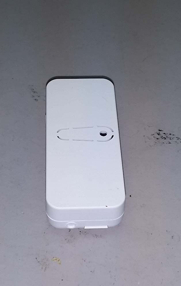
Click to zoom
Application Details
- Equipment Class
- DXX - Part 15 Low Power Communication Device Transmitter
- Date of Grant
- Apr 29, 2015
- Application Purpose
- Original Equipment
- Date of Application
- Apr 29, 2015
- Equipment Note
- Door/window Sensors used by Security System
- Frequency Range
- 319.50800000 - 319.50800000
- Company
- Cinch Systems, Inc
- Country
- United States
Documents & Files
Document Text
Text extracted from the exhibit documents filed with the FCC. Open a document above to read the original.
Users Manual
RF-HLTS Micro Wireless High/Low Temperature Sensor Installation Instruction Micro Wireless Temperature Sensor and Accessories 1 - RF-HLTS Sensor 1- Mounting Tape 2 - Batteries ( 2- 3VDC CR 2032) Instructions Tamper switch Doc # I-RF-HLTS Rev. A Jan 2015 Programming: 1. Enter system programming and select Auto Learn Sensors 2. Freeze Sensor Enrollment Remove the sensor cover allowing the tam- per to trip, the panel will respond Select Freeze as sensor type and add sensor 3. Heat Sensor Enrollment Remove both of the sensors batteries While holding down the tamper insert the batteries, the panel will respond Select Heat as sensor type and add sensor Note: The sensor has 2 unique ID numbers allowing it to report both freeze and heat alarms independently. The sensor can be programmed for just freeze or just heat or both. Cover Latch Cover Latch Tamper Base Note: Battery Safety Observe polarity when inserting re- placement batteries to avoid damag- ing the sensor. Risk of fire, burns and explosion. Do not recharge, disassemble, burn or expose batteries to temperatures above 100C (212F) Dispose of used batteries properly and in accordance with all local laws Keep batteries away from children Batteries RF-HLTS Micro Wireless High/Low Temperature Sensor Installation Instruction Micro Wireless Temperature Sensor and Accessories 1 - RF-HLTS Sensor 1- Mounting Tape 2 - Batteries ( 2- 3VDC CR 2032) Instructions Tamper switch Doc # I-RF-HLTS Rev. A Jan 2015 Programming: 1. Enter system programming and select Auto Learn Sensors 2. Freeze Sensor Enrollment Remove the sensor cover allowing the tam- per to trip, the panel will respond Select Freeze as sensor type and add sensor 3. Heat Sensor Enrollment Remove both of the sensors batteries While holding down the tamper insert the batteries, the panel will respond Select Heat as sensor type and add sensor Note: The sensor has 2 unique ID numbers allowing it to report both freeze and heat alarms independently. The sensor can be programmed for just freeze or just heat or both. Cover Latch Cover Latch Tamper Base Note: Battery Safety Observe polarity when inserting re- placement batteries to avoid damag- ing the sensor. Risk of fire, burns and explosion. Do not recharge, disassemble, burn or expose batteries to temperatures above 100C (212F) Dispose of used batteries properly and in accordance with all local laws Keep batteries away from children Batteries Mounting Doc # I-RF-HLTS Rev. A Jan 2015 Specifications: Features: Freeze and Overheat Warning Freeze Alarm : Temperature drops below 40F, restore when temperature rises above 45F. Heat Alarm: Temperature rises above 100F, restores when temperature drops below 95F. Sensor: Cover tamper Unique ID for each function Temperature check every 5 minutes Battery checked every hour Batteries: (2) - Panasonic CR2032 Energizer CR2032 Duracell DL2032 When mounting the wireless device make sure it is not mounted on metal, also avoid large metal ob- structions between the sensor and panel, this can be tested prior to or after installation Freeze Sensor Mounting Using the supplied mounting tape find a location that would most likely get cold first (alarm trips at 40F) for example: Under a kitchen sink In the bathroom Avoid area that may retain heat as furnace rooms or near hot water pipes Heat Sensor Mounting Heat sensors are designed to detect an impending fire in areas that are prone to false alarms due to smoke. Locate the sensor up as high as possible as heat rises, the sensor detects at 100F Kitchen Garage Furnace room FCC label statement: “This device complies with part 15 of the FCC Rules. Operation is subject to the following two conditions: (1) This device may not cause harmful interference, and (2) this device must accept any interference received, including interference that may cause undesired operation.” “Note: This equipment has been tested and found to comply with the limits for a Class B digital device, pursuant to part 15 of the FCC Rules. These limits are designed to provide reasonable protection against harmful interference in a residential installation. This equipment generates, uses and can radiate radio frequency energy and, if not installed and used in accordance with the instructions, may cause harmful interference to radio communications. However, there is no guarantee that interference will not occur in a particular installation. If this equip- ment does cause harmful interference to radio or television reception, which can be determined by turning the equipment off and on, the user is encouraged to try to correct the interference by one or more of the following measures: —Reorient or relocate the receiving antenna. —Increase the separation between the equipment and receiver. —Connect the equipment into an outlet on a circuit different from that to which the receiver is connected. —Consult the dealer or an experienced radio/TV technician for help.” “Changes or modifications not expressly approved by the party responsible for compliance could void the user's authority to operate the equipment” “RF Exposure Guidance: This equipment complies with FCC radiation exposure limits set forth for an uncontrolled environment. This equipment should be installed and operated with a minimum distance of 1.5cm between the radiator and persons. This transmitter must not be co-located or operating in conjunction with any other antenna or transmitter, except in accordance with FCC multi-transmitter product procedures.” I.C. label Statement: IC: 11817A-RFMDWS “This device complies with Industry Canada licence-exempt RSS standard(s). Operation is subject to the following two conditions: (1) this device may not cause interference, and (2) this device must accept any interference, including interfer- ence that may cause undesired operation of the device. Le présent appareil est conforme aux CNR d'Industrie Canada applicables aux appareils radio exempts de licence. L'exploitat…
Text truncated - open the document above for the full version.
Users Manual
Mini DW Ext Terminal—Installation Instructions Micro Wireless Sensor and Accessories 1 - RF-MDWSX Sensor 1- Mounting Tape 1 - Magnet 2 - Batteries ( 2- 3VDC CR 2032) Instructions Tamper switch Doc # I-RF-MDWSX Rev. A Sep 2014 Installation 1. Remove the transmitter’s cover by pressing in on the small rectangular latch on the end of the cover and lift up 2. Mount the sensor base directly to the surface us- ing the mounting tape provided. Make sure to align the mounting tape with the tamper pull put area on the bottom of the sensor to insure proper tamper operation. 3. Mount the magnet next to the sensor and align the magnet with the mark on the side of the sen- sor, using the mounting tape provided, or connect an external contact to the terminals 4. Remove the battery isolator tabs from both batter- ies on the sensor 5. Replace the cover on the transmitter 6. Enroll the senor into the control panel according the instructions Note: Mounting the transmitter onto metal surfaces may impact the effective range of the transmitter Cover Latch Cover Latch Tamper Base Note: Battery Safety Observe polarity when inserting replacement batteries to avoid dam- aging the sensor. Risk of fire, burns and explosion. Do not recharge, disassemble, burn or expose batteries to temperatures above 100C (212F) Dispose of used batteries properly and in accordance with all local laws Keep batteries away from children Batteries Terminals Mini DW Ext Terminal—Installation Instructions Micro Wireless Sensor and Accessories 1 - RF-MDWSX Sensor 1- Mounting Tape 1 - Magnet 2 - Batteries ( 2- 3VDC CR 2032) Instructions Tamper switch Doc # I-RF-MDWSX Rev. A Sep 2014 Installation 1. Remove the transmitter’s cover by pressing in on the small rectangular latch on the end of the cover and lift up 2. Mount the sensor base directly to the surface us- ing the mounting tape provided. Make sure to align the mounting tape with the tamper pull put area on the bottom of the sensor to insure proper tamper operation. 3. Mount the magnet next to the sensor and align the magnet with the mark on the side of the sen- sor, using the mounting tape provided, or connect an external contact to the terminals 4. Remove the battery isolator tabs from both batter- ies on the sensor 5. Replace the cover on the transmitter 6. Enroll the senor into the control panel according the instructions Note: Mounting the transmitter onto metal surfaces may impact the effective range of the transmitter Cover Latch Cover Latch Tamper Base Note: Battery Safety Observe polarity when inserting replacement batteries to avoid dam- aging the sensor. Risk of fire, burns and explosion. Do not recharge, disassemble, burn or expose batteries to temperatures above 100C (212F) Dispose of used batteries properly and in accordance with all local laws Keep batteries away from children Batteries Terminals Mounting Using pre-cut tape, mount the sensor on the non-moving frame and the magnet on the door or window Magnet locator mark Magnet gap should not exceed 5/8” if needed use magnet spacers to align mag- net to sensor Magnet spacers are stacked under the magnet Doc # I-RF-MDWSX Rev. A Sep 2014 Specifications: Dimensions: 2.5 X 1 X .5 Batteries: (2) - Panasonic CR2032 Energizer CR2032 Duracell DL2032 2.5” .5” 1” When using the external terminals the sensor can be mounted away from the opening and a wire run to the contact FCC label statement: “This device complies with part 15 of the FCC Rules. Operation is subject to the following two conditions: (1) This device may not cause harmful interference, and (2) this device must accept any interference received, including interference that may cause undesired operation.” “Note: This equipment has been tested and found to comply with the limits for a Class B digital device, pursuant to part 15 of the FCC Rules. These limits are designed to provide reasonable protection against harmful interference in a residential installation. This equipment generates, uses and can radiate radio frequency energy and, if not installed and used in accordance with the instructions, may cause harmful interference to radio communications. However, there is no guarantee that interference will not occur in a particular installation. If this equip- ment does cause harmful interference to radio or television reception, which can be determined by turning the equipment off and on, the user is encouraged to try to correct the interference by one or more of the following measures: —Reorient or relocate the receiving antenna. —Increase the separation between the equipment and receiver. —Connect the equipment into an outlet on a circuit different from that to which the receiver is connected. —Consult the dealer or an experienced radio/TV technician for help.” “Changes or modifications not expressly approved by the party responsible for compliance could void the user's authority to operate the equipment” “RF Exposure Guidance: This equipment complies with FCC radiation exposure limits set forth for an uncontrolled environment. This equipment should be installed and operated with a minimum distance of 1.5cm between the radiator and persons. This transmitter must not be co-located or operating in conjunction with any other antenna or transmitter, except in accordance with FCC multi-transmitter product procedures.” I.C. label Statement: IC: 11817A-RFMDWS “This device complies with Industry Canada licence-exempt RSS standard(s). Operation is subject to the following two conditions: (1) this device may not cause interference, and (2) this device must accept any interference, including interfer- ence that may cause undesired operation of the device. Le présent appareil est conforme aux CNR d'Industrie Canada applicables aux appareils radio exempts de licence. L'exploitation est autorisée aux deux conditions suivantes : (1) l'appareil ne doit pas produire de brouillage, et (2) l'utilisateur de l'appareil doit accepter tout brouillage radioélectrique subi, même si le brouillag…
Text truncated - open the document above for the full version.
Users Manual
Mini DW Sensor—Installation Instructions Micro Wireless Sensor and Accessories 1 - RF-MDWS Sensor 1- Mounting Tape 1 - RF-MDWS Magnet 2 - Batteries ( 2- 3VDC CR 2032) Instructions Tamper switch Doc # I-RF-MDWS Rev. A Sep 2014 Installation 1. Remove the transmitter’s cover by pressing in on the small rectangular latch on the end of the cover and lift up 2. Mount the sensor base directly to the surface using the mounting tape provided. Make sure to align the mounting tape with the tamper pull put area on the bottom of the sensor to insure proper tamper opera- tion. 3. Mount the magnet next to the sensor and align the magnet with the mark on the side of the sensor, using the mounting tape provided 4. Remove the battery isolator tabs from both batteries on the sensor 5. Replace the cover on the transmitter 6. Enroll the senor into the control panel according the instructions Note: Mounting the transmitter onto metal surfaces may impact the effective range of the transmitter Cover Latch Cover Latch Tamper Base Note: Battery Safety Observe polarity when inserting replacement batteries to avoid damaging the sensor. Risk of fire, burns and explosion. Do not recharge, disassemble, burn or expose batteries to tempera- tures above 100C (212F) Dispose of used batteries properly and in accordance with all local laws Keep batteries away from children Batteries Mini DW Sensor—Installation Instructions Micro Wireless Sensor and Accessories 1 - RF-MDWS Sensor 1- Mounting Tape 1 - RF-MDWS Magnet 2 - Batteries ( 2- 3VDC CR 2032) Instructions Tamper switch Doc # I-RF-MDWS Rev. A Sep 2014 Installation 1. Remove the transmitter’s cover by pressing in on the small rectangular latch on the end of the cover and lift up 2. Mount the sensor base directly to the surface using the mounting tape provided. Make sure to align the mounting tape with the tamper pull put area on the bottom of the sensor to insure proper tamper opera- tion. 3. Mount the magnet next to the sensor and align the magnet with the mark on the side of the sensor, using the mounting tape provided 4. Remove the battery isolator tabs from both batteries on the sensor 5. Replace the cover on the transmitter 6. Enroll the senor into the control panel according the instructions Note: Mounting the transmitter onto metal surfaces may impact the effective range of the transmitter Cover Latch Cover Latch Tamper Base Note: Battery Safety Observe polarity when inserting replacement batteries to avoid damaging the sensor. Risk of fire, burns and explosion. Do not recharge, disassemble, burn or expose batteries to tempera- tures above 100C (212F) Dispose of used batteries properly and in accordance with all local laws Keep batteries away from children Batteries FCC label statement: “This device complies with part 15 of the FCC Rules. Operation is subject to the following two conditions: (1) This device may not cause harmful interference, and (2) this device must accept any interference received, including interference that may cause undesired operation.” “Note: This equipment has been tested and found to comply with the limits for a Class B digital device, pursuant to part 15 of the FCC Rules. These limits are designed to provide reasonable protection against harmful interference in a residential installation. This equipment generates, uses and can radiate radio frequency energy and, if not installed and used in accordance with the instructions, may cause harmful interference to radio communications. However, there is no guarantee that interference will not occur in a particular installation. If this equip- ment does cause harmful interference to radio or television reception, which can be determined by turning the equipment off and on, the user is encouraged to try to correct the interference by one or more of the following measures: —Reorient or relocate the receiving antenna. —Increase the separation between the equipment and receiver. —Connect the equipment into an outlet on a circuit different from that to which the receiver is connected. —Consult the dealer or an experienced radio/TV technician for help.” “Changes or modifications not expressly approved by the party responsible for compliance could void the user's authority to operate the equipment” “RF Exposure Guidance: This equipment complies with FCC radiation exposure limits set forth for an uncontrolled environment. This equipment should be installed and operated with a minimum distance of 1.5cm between the radiator and persons. This transmitter must not be co-located or operating in conjunction with any other antenna or transmitter, except in accordance with FCC multi-transmitter product procedures.” I.C. label Statement: IC: 11817A-RFMDWS “This device complies with Industry Canada licence-exempt RSS standard(s). Operation is subject to the following two conditions: (1) this device may not cause interference, and (2) this device must accept any interference, including interfer- ence that may cause undesired operation of the device. Le présent appareil est conforme aux CNR d'Industrie Canada applicables aux appareils radio exempts de licence. L'exploitation est autorisée aux deux conditions suivantes : (1) l'appareil ne doit pas produire de brouillage, et (2) l'utilisateur de l'appareil doit accepter tout brouillage radioélectrique subi, même si le brouillage est susceptible d'en compromettre le fonctionnement. » Under Industry Canada regulations, this radio transmitter may only operate using an antenna of a type and maximum (or lesser) gain approved for the transmitter by Industry Canada. To reduce potential radio interference to other users, the antenna type and its gain should be so chosen that the equivalent isotropically radiated power (e.i.r.p.) is not more than that necessary for successful communication. Conformément à la réglementation d'Industrie Canada, le présent émetteur radio peut fonctionner avec une antenne d'un type et d'un gain maximal (ou inférieur) approuvé pour l'émetteur par I…
Text truncated - open the document above for the full version.
Users Manual
RF-MDWSX-Water Micro Wireless Sensor Installation Instruction Micro Wireless Water Sensor and Accessories 1 - RF-MDWS-Water Sensor 1- Mounting Tape 1 - Water Detector 2 - Batteries ( 2- 3VDC CR 2032) Instructions Tamper switch Doc # I-RF-MDWSX-Water Rev. A Features: Water detection when liquid rises above contacts Contacts above floor level to prevent false floor condensa- tion detection Checks for water every 5 minutes, requires two positive checks for a valid alarm Programming: 1. Enter system programming and select Auto Learn Sensors 2. Remover cover from sensor to trip tamper 3. Qolsys panel displays Auto Learn Sensor 4. Press OK 5. Set senor type to Water 6. Select a sensor name 7. Press Add New 8. Exit program or trip next sensor to program Cover Latch Note: Battery Safety Observe polarity when inserting re- placement batteries to avoid damag- ing the sensor. Risk of fire, burns and explosion. Do not recharge, disassemble, burn or expose batteries to temperatures above 100C (212F) Dispose of used batteries properly and in accordance with all local laws Keep batteries away from children Batteries Water Detector RF-MDWSX-Water Micro Wireless Sensor Installation Instruction Micro Wireless Water Sensor and Accessories 1 - RF-MDWS-Water Sensor 1- Mounting Tape 1 - Water Detector 2 - Batteries ( 2- 3VDC CR 2032) Instructions Tamper switch Doc # I-RF-MDWSX-Water Rev. A Features: Water detection when liquid rises above contacts Contacts above floor level to prevent false floor condensa- tion detection Checks for water every 5 minutes, requires two positive checks for a valid alarm Programming: 1. Enter system programming and select Auto Learn Sensors 2. Remover cover from sensor to trip tamper 3. Qolsys panel displays Auto Learn Sensor 4. Press OK 5. Set senor type to Water 6. Select a sensor name 7. Press Add New 8. Exit program or trip next sensor to program Cover Latch Note: Battery Safety Observe polarity when inserting re- placement batteries to avoid damag- ing the sensor. Risk of fire, burns and explosion. Do not recharge, disassemble, burn or expose batteries to temperatures above 100C (212F) Dispose of used batteries properly and in accordance with all local laws Keep batteries away from children Batteries Water Detector FCC label statement: “This device complies with part 15 of the FCC Rules. Opera- tion is subject to the following two conditions: (1) This device may not cause harmful interference, and (2) this device must accept any interference received, including interference that may cause undesired operation.” “Note: This equipment has been tested and found to comply with the limits for a Class B digital device, pursuant to part 15 of the FCC Rules. These limits are designed to provide reason- able protection against harmful interference in a residential installation. This equipment generates, uses and can radiate radio frequency energy and, if not installed and used in accordance with the instructions, may cause harmful interfer- ence to radio communications. However, there is no guaran- tee that interference will not occur in a particular installation. If this equipment does cause harmful interference to radio or television reception, which can be determined by turning the equipment off and on, the user is encouraged to try to correct the interference by one or more of the following measures: —Reorient or relocate the receiving antenna. —Increase the separation between the equipment and receiver. —Connect the equipment into an outlet on a circuit different from that to which the receiver is connected. —Consult the dealer or an experienced radio/TV technician for help.” “Changes or modifications not expressly approved by the party responsible for compliance could void the user's author- ity to operate the equipment” “RF Exposure Guidance: This equipment complies with FCC radiation exposure limits set forth for an uncontrolled envi- ronment. This equipment should be installed and operated with a minimum distance of 1.5cm between the radiator and persons. This transmitter must not be co-located or operating in conjunction with any other antenna or transmitter, except in accordance with FCC multi-transmitter product proce- dures.” Installation Doc # I-RF-MDWSX-Water Rev. A Specifications: Features: Detector: Dual water sensor probes Above floor detection 72” cable length Sensor: Cover tamper Unique ID for each function Temperature check every 5 minutes Battery checked every hour Batteries: (2) - Panasonic CR2032 Energizer CR2032 Duracell DL2032 When mounting the wireless device make sure it is not mounted on metal or there are any large metal objects between the device and the control panel, this can be tested prior to or after installation Water Detector Mounting: Mount the sensor as high as possible, the water de- tector has a 72” cable attaching it to the sensor The water detector can be mounted to the wall or floor using mounting screws Mount sensor using supplied hardware Detector mounts directly to the floor or can be attached to a wall FCC label statement: “This device complies with part 15 of the FCC Rules. Opera- tion is subject to the following two conditions: (1) This device may not cause harmful interference, and (2) this device must accept any interference received, including interference that may cause undesired operation.” “Note: This equipment has been tested and found to comply with the limits for a Class B digital device, pursuant to part 15 of the FCC Rules. These limits are designed to provide reason- able protection against harmful interference in a residential installation. This equipment generates, uses and can radiate radio frequency energy and, if not installed and used in accordance with the instructions, may cause harmful interfer- ence to radio communications. However, there is no guaran- tee that interference will not occur in a particular installation. If this equipment does cause harmful interference to radio or televisi…
Text truncated - open the document above for the full version.
Users Manual
FCC/IC statement are printed inside box, for all QSxxxx part numbers Here is the content inside all packages: FCC label statement: “This device complies with part 15 of the FCC Rules. Operation is subject to the following two conditions: (1) This device may not cause harmful interference, and (2) this device must accept any interference received, including interference that may cause undesired operation.” “Note: This equipment has been tested and found to comply with the limits for a Class B digital device, pursuant to part 15 of the FCC Rules. These limits are designed to provide reasonable protection against harmful interference in a residential installation. This equipment generates, uses and can radiate radio frequency energy and, if not installed and used in accordance with the instructions, may cause harmful interference to radio communications. However, there is no guarantee that interference will not occur in a particular installation. If this equip‐ment does cause harmful interference to radio or television reception, which can be determined by turning the equipment off and on, the user is encouraged to try to correct the interference by one or more of the following measures: —Reorient or relocate the receiving antenna. —Increase the separation between the equipment and receiver. —Connect the equipment into an outlet on a circuit different from that to which the receiver is connected. —Consult the dealer or an experienced radio/TV technician for help.” “Changes or modifications not expressly approved by the party responsible for compliance could void the user's authority to operate the equipment” “RF Exposure Guidance: This equipment complies with FCC radiation exposure limits set forth for an uncontrolled environment. This equipment should be installed and operated with a minimum distance of 1.5cm between the radiator and persons. This transmitter must not be co‐ located or operating in conjunction with any other antenna or transmitter, except in accordance with FCC multi‐transmitter product procedures.” I.C. label Statement: IC: 11817A‐RFMDWS “This device complies with Industry Canada licence‐exempt RSS standard(s). Operation is subject to the following two conditions: (1) this device may not cause interference, and (2) this device must accept any interference, including interfer‐ence that may cause undesired operation of the device. Le présent appareil est conforme aux CNR d'Industrie Canada applicables aux appareils radio exempts de licence. L'exploitation est autorisée aux deux conditions suivantes : (1) l'appareil ne doit pas produire de brouillage, et (2) l'utilisateur de l'appareil doit accepter tout brouillage radioélectrique subi, même si le brouillage est susceptible d'en compromettre le fonctionnement. » Under Industry Canada regulations, this radio transmitter may only operate using an antenna of a type and maximum (or lesser) gain approved for the transmitter by Industry Canada. To reduce potential radio interference to other users, the antenna type and its gain should be so chosen that the equivalent isotropically radiated power (e.i.r.p.) is not more than that necessary for successful communication.
External Photos
Models RF-MDWS-ITI,RF-HLTS-ITI, QS1116-840, QS5515-840 Top & Back View Top and Front View Bottom & Front View Bottom and Back View Side View Alternate Side View Models RF-MDWSX-ITI, RF-MDWSX-Water-ITI, QS1117-840, QS5516-840 Top and Back View Top and Front View Bottom and Back Bottom and Front Side View Alternate Side View
ID Label/Location Info
Label Samples Labels are UL Listed and utilize permanent adhesive. Tyco P/N WP-040040-10-9 Applied by hand Mini Door/Window Sensor – Model RF-MDWS-ITI Mini Door/Window Sensor – Model QS1116-840 Mini Temp Sensor – Model RF-HLTS-ITI Mini Temp Sensor – Model QS5515-840 DW Ext Term- Water – Model RF-MDWSX-Water-ITI DW Ext Term- Water – Model QS5516-840 Mini DWS-Extended – Model RF-MDWSX-ITI Mini DWS-Extended – Model QS1117-840
Internal Photos
RF-MDWS-ITI and QS1116-840-Top RF-MDWS-ITI and QS1116-840-Bottom RF-MDWS-HLTS-ITI and QS5515-840-Top RF-MDWS-HLTS-ITI and QS5515-840-Bottom RF-MDWSX-ITI and QS1117-840-Top RF-MDWSX-Water-ITI and QS5516-840 are same as above RF-MDWSX-ITI and QS1117-840-Bottom RF-MDWSX-Water-ITI and QS5516-840 are same as above
Test Report
TÜV SÜD AMERICA INC 1775 Old Hwy 8 NW, Suite 104 New Brighton MN 55112-1891 Tel: (651) 638-0297 Fax: (651) 638-0298 Rev. 113006 TEST REPORT FCC Part 15 Subpart C Section 15.231 IC RSS-210 Issue 8 IC RSS-Gen Issue 4 MANUFACTURER'S NAME Cinch Systems Inc 12075 43rd Street NE Suite 300 St Michael MN 55376 USA PRODUCT NAME Micro Door Window Sensor Micro DWS-External contact MODEL NUMBER(S) TESTED RF-MDWS-ITI RF-MDWSX-ITI SERIAL NUMBER(S) TESTED 7 1 PRODUCT DESCRIPTION Micro Door Window Sensors with 319.5 MHz transmitters TEST REPORT NUMBER NC1409669.1 Rev A TEST DATE(S) 07-10 October 2014 TÜV SÜD America Inc, as an independent testing laboratory, declares that the equipment tested as specified above conforms to the applicable EMC requirements of FCC Part 15 Subpart C Section 15.231 “Periodic operation in the band 40.66–40.70 MHz and above 70 MHz.” and Industry Canada RSS-210 Issue 8 “Licence-exempt Radio Apparatus (All Frequency Bands): Category I Equipment” and Industry Canada RSS-Gen Issue 4 “General Requirements and Information for the Certification of Radio Apparatus”. It is the manufacturer's responsibility to assure that additional production units of this model are manufactured with identical electrical and mechanical characteristics. Any modifications necessary for compliance made during testing on the above mentioned date(s) must be implemented in all production units for compliance to be maintained. Issue Date: 29 April 2015 Joel T Schneider Greg Jakubowski Senior EMC Engineer Senior EMC Technician Not Transferable FCC ID: 2ABBZ-RF-MDWS IC: 11817A-RFMDW TÜV SÜD AMERICA INC 1775 Old Hwy 8 NW, Suite 104 New Brighton MN 55112-1891 Tel: (651) 638-0297 Fax: (651) 638-0298 Rev. 113006 EMC TEST REPORT Test Report No. NC1409669.1 R…
Text truncated - open the document above for the full version.
Contact Information
Applicant
Joel C Christianson(CEO)
Test Firm
TUV SUD America Inc.William Elliott
Technical Specifications
| # | Rule Parts | Frequency Range | Power Output |
|---|---|---|---|
| 1 | 15C | 319.508 MHz - 319.508 MHz | - |
Other Applications from Cinch Systems, Inc
2ABBZ-RF-ROR-V3-319
Jun 10, 2026RF-ROR-V3-319-NN
Equipment Class
DSC - Part 15 Security/Remote Control Transmitter2ABBZ-RF-ARGB-319V3
Apr 07, 2026Wireless Glass Break Sensor
Equipment Class
DSC - Part 15 Security/Remote Control Transmitter2ABBZ-R-QS5230-840
Dec 01, 2025Wireless CO Detector
Equipment Class
DSC - Part 15 Security/Remote Control Transmitter2ABBZ-RF-CO-319
Nov 25, 2025Wireless CO Detector
Equipment Class
DSC - Part 15 Security/Remote Control Transmitter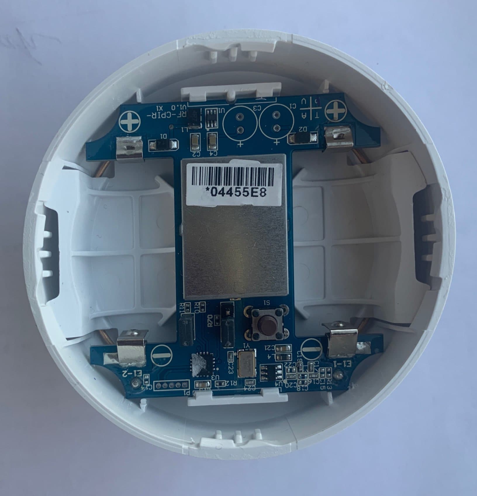
2ABBZ-RF-360PIR-433
Jun 28, 2021RF-CPIR-433, CLR-C1-360PIR
Equipment Class
DSC - Part 15 Security/Remote Control Transmitter