2ABBZ-RF-RDWS-345RF-RDWS-345-NN
Cinch Systems, Inc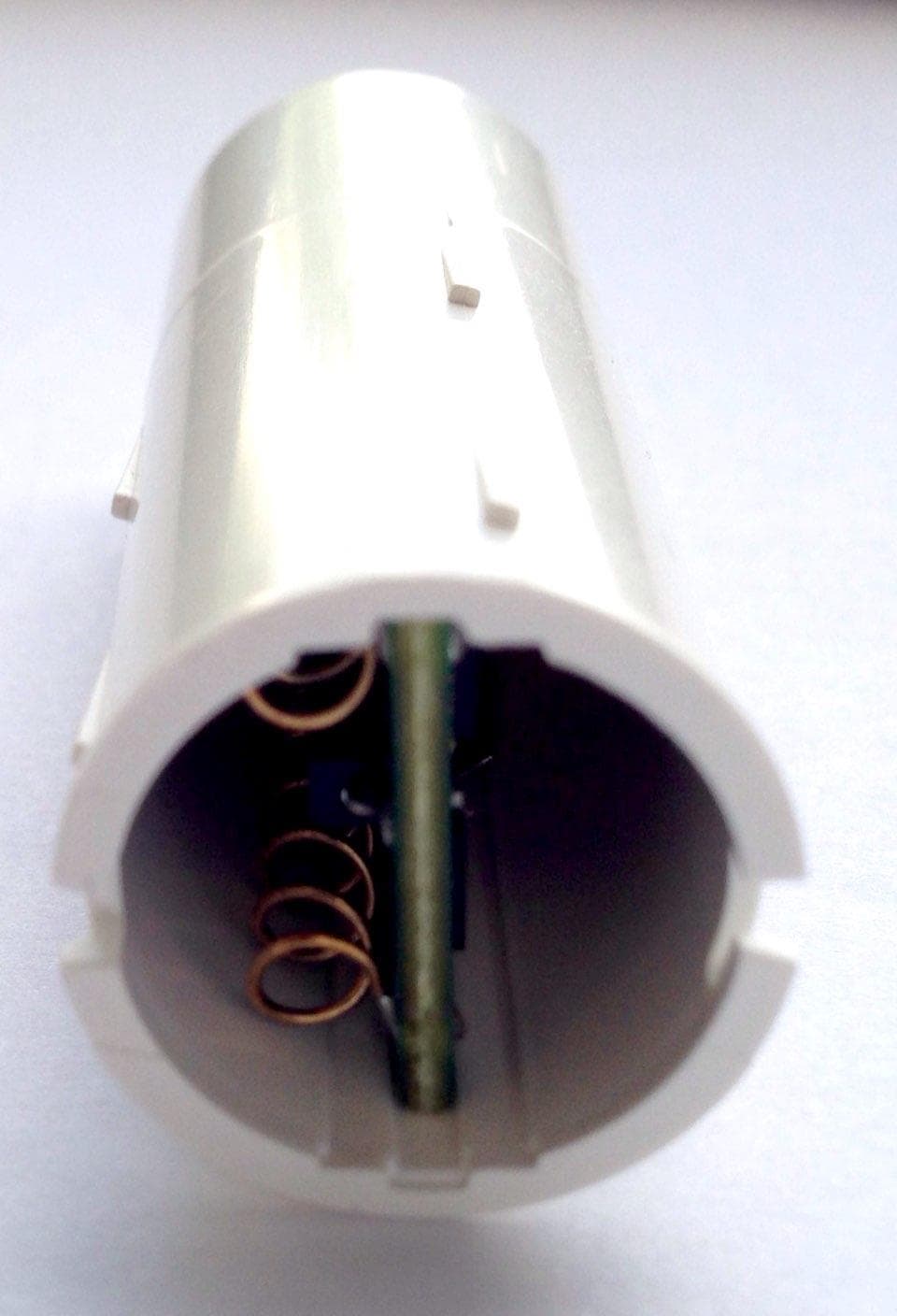
Click to zoom
Application Details
- Equipment Class
- DSC - Part 15 Security/Remote Control Transmitter
- Date of Grant
- Jun 28, 2021
- Application Purpose
- Original Equipment
- Date of Application
- Jun 28, 2021
- Equipment Note
- RF-RDWS-345-NN
- Frequency Range
- 345.00000000 - 345.00000000
- Company
- Cinch Systems, Inc
- Country
- United States
Documents & Files
Document Text
Text extracted from the exhibit documents filed with the FCC. Open a document above to read the original.
Users Manual
Wireless Recessed Door/Window Sensor RF-RDWS-345-NN Installation Instructions RF-RDWS-345-NN IM V1 08042020 Description The Recessed Door/Window Sensor is a supervised, wireless sensor that detects the opening and closing of doors or windows. The sensor and magnet are recessed mounted into the frame. When activated, the sensor transmits an open (trip) or close (restore) signal to the panel. These are the signals the unit provides: supervisory and low battery (as needed). The sensor is powered by (1) replaceable 3-VDC, lithium battery. Mounting the Sensor • Verify mounting location before drilling any holes, the area must be able to accept an 11/16” hole to a depth of 2 1/4” for the sensor and 5/8” for the magnet • The holes must be drilled directly across from each other to ensure the magnet and sensor operate properly • Using an 11/16” drill bit drill the hole for the magnet first, after drilling the magnet hole mark the location directly across for the sensor hole. • The magnet and sensor are slightly larger than the drilled hole to ensure a snug fit, a small amount of routing the hole may be required • Push both magnet and sensor into mounting holes Programming The following steps describe the general guidelines for programming the sensor into panel memory. Refer to the specific panel’s documentation for complete programming details. 1. Set the panel to the program mode. 2. Proceed to the SENSORS menu. 3. Select the appropriate sensor group and sensor number assignments. 4. When prompted by the panel to trip the sensor for learning: • Remove the cap from the sensor by using a screwdriver and twisting the cap • Pull the battery tab out to power the sensor • After the battery tab is pulled the sensor will transmit “tampers” for the first fives activations, the sensor should be enrolled during one of these first five trips. If the device is tripped too many times before enrollment the battery must be removed and re- installed to activate the tamper trips again. 5. Exit program mode. Testing the Sensor 1. Set the panel to the sensor test mode. 2. Monitor the system after tripping the sensor. Refer to the specific panel documentation for interpretation of the results to ensure desired signal strength is achieved. Note: If a low battery alarm occurs, replace the battery within 7 days. CAUTION: Battery may explode if mistreated. Do not recharge, disassemble or dispose of in fire. Battery Replacement • Remove the sensor cap and carefully pull out the circuit board. • Push out the old battery towards the antennas and replace with a new battery. • Carefully slide board back into housing, note the slot for alignment. • Replace the cap and activate the device at least five times. Sp Mount in top or side of door Wireless Recessed Door/Window Sensor RF-RDWS-345-NN Installation Instructions RF-RDWS-345-NN IM V1 08042020 Specifications Model no. RF-RDWS-345-NN RF frequency 345 MHz Compatibility Interlogix Learn Mode Panels and Receivers – Concord, NetworX and Simon Series Battery type (1) 3-VDC, lithium battery (Varta or Panasonic, Battery Panasonic CR2 Operating temperature range 32 to 120°F (0 to 49°C) Storage temperature range -30 to 140°F (-34 to 60°C) Relative humidity 95% non-condensing Dimensions 2.25” L x .75” D FCC / IC Statement This equipment has been tested and found to comply with the limits for a Class B digital device, pursuant to Part 15 of the FCC Rules. These limits are designed to provide reasonable protection against harmful interference in a residential installation. Per FCC 15.19 (a) (3) and (a) (4), This device complies with part 15 of the FCC Rules. Operation is subject to the following conditions: (1) this device may not cause harmful interference, and (2) this device must accept any interference received, including interference that may cause undesirable operation. Per FCC 15.21, The user manual or instruction manual for an intentional or unintentional radiator shall caution the user that changes or modifications not expressly approved by the party responsible for compliance could void the user's authority to operate the equipment. This equipment generates, uses and can radiate radio frequency energy and, if not installed and used in accordance with the instructions, may cause harmful interference to radio communications. However, there is no guarantee that interference will not occur in a particular installation. If this equipment does cause harmful interference to radio or television reception, which can be determined by turning the equipment off and on, the user is encouraged to try to correct the interference by one or more of the following measures: • Reorient or relocate the receiving antenna. • Increase the separation between the equipment and receiver. • Connect the equipment into an outlet on a circuit different from that to which the receiver is connected. • Consult the dealer or an experienced radio/TV technician for help. This device complies with Industry Canada license-exempt RSS standard(s). Operation is subject to the following two conditions: (1) this device may not cause interference, and (2) this device must accept any interference, including interference that may cause undesired operation of the device. Cet appareil est conforme avec Industrie Canada exempts de licence standard RSS (s). Son fonctionnement est soumis aux deux conditions suivantes: (1) cet appareil ne doit pas provoquer d'interférences et (2) cet appareil doit accepter toute interférence, y compris celles pouvant causer un mauvais fonctionnement de l'appareil. In accordance with FCC requirements of human exposure to radio frequency fields, the radiating element shall be installed such that a minimum separation distance of 20 cm is maintained from the general population. FCC: 2ABBZ-RF-RDWS-345 IC: 11817A-RFRDWS345 This device complies with Part 15 of the FCC Rules. Operation is subject to the following two conditions: (1) This device may not cause harmful interference, and (2) this device mu…
Text truncated - open the document above for the full version.
Cover Letter(s)
Cinch Systems, Inc. 12075 43 rd St NE Suite 300 St. Michael MN 55376 USA Application Cover Letter FCC ID: 2ABBZ-RF-RDWS-345 Cinch Security Systems is applying for original certification to FCC Part 15 Subpart C §15.231 for FCC ID number 2ABBZ-RF-RDWS-345 is door window sensor. The wireless communication interface with a security panel is regarded as a proprietary security protocol. The following model numbers are associated with this application: • RF-RDWS-345-NN Company Officer: Vice President Telephone Number: 763-497-1059 Email: [email protected]
Cover Letter(s)
Cinch Systems, Inc. 12075 43 rd St NE Suite 300 St Michael, MN 55376 USA Confidentiality Request FCC ID: 2ABBZ-RF-RDWS-345 Pursuant to Sections 0.457(d) and 0.459 of the Commission’s Rules, Cinch Systems hereby requests permanent confidential treatment of information accompanying this application as outlined below: Common exhibits for which confidentiality is requested are: Schematics: Block Diagrams: Theory of Operation: Cinch Systems also hereby requests short-term confidential treatment of information accompanying this application as outlined below for a period of 180 days: Exhibits for which short-term confidentiality is commonly requested are: Internal Photos: External Photos: User Manual: Test Set-up Photographs: The above materials contain trade secrets and proprietary information not customarily released to the public. The public disclosure of these matters might be harmful to the Applicant and provide unjustified benefits to its competitors. The Applicant understands that pursuant to Rule 0.457(d)(1)(ii), disclosure of this Application and all accompanying materials will not be made before the date of the Grant for this Application. Company Officer: Vice President Telephone Number: 763-497-1059 Email: [email protected]
External Photos
External photo:
ID Label/Location Info
Model: RF-RDWS-345-NN Cinch Systems Inc. FCC ID: 2ABBZ-RF-RDWS-345 Model: RF-RDWS-345-NN IC : 11817A-RFRDWS345
Internal Photos
Internal device Pictures.
Operational Description
RF-RDWS-345-NN Antenna info Overview: Antenna description: • The antenna is a piece of wire and used in a monopole arrangement. Antenna is permanently attached to the unit. The antenna does not use reverse polarity connector. • Both antenna characteristic was the same Antenna Drawing: Antenna design: Left Antenna Antenna specification Frequency band 345MHz Frequency (MHz) 325 330 345 450 355 Return loss (dB) < -13 Peak gain (dBi) 0.412 0.22 -0.93 1.67 1.87 Average gain (dBi) -1.34 -3.6 -2.95 -1.9 -1.97 Efficiency (%) 33.8 37.86 48.8 68.3 68.83 Right Antenna Antenna specification Frequency band 345MHz Frequency (MHz) 325 330 345 450 355 Return loss (dB) < -13 Peak gain (dBi) 0.412 0.22 -0.93 1.67 1.87 Average gain (dBi) -1.34 -3.6 -2.95 -1.9 -1.97 Efficiency (%) 33.8 37.86 48.8 68.3 68.83
Test Report
This report must not be used to claim product certification, approval, or endorsement by NVLAP, NIST, or any agency of the U.S. Government. This Report shall not be reproduced, except in full without written approval of the laboratory. CINCH Systems RF-RDWS-345-NN FCC 15.231:2021 Periodic Radio Report: CINC0058.1, Issue Date: June 16, 2021 NVLAP LAB CODE: 200881-0 CERTIFICATE OF TEST 2018-09-14 Product compliance is the responsibility of the client; therefore, the tests and equipment modes of operation represented in this report were agreed upon by the client, prior to testing. The results of this test pertain only to the sample(s) tested. The specific description is noted in each of the individual sections of the test report supporting this certificate of test. This report reflects only those tests from the referenced standards shown in the certificate of test. It does not include inspection or verification of labels, identification, marking or user information. As indicated in the Statement of Work sent with the quotation, Element’s standard process is to always use the latest published version of the test methods even when earlier versions are cited in the test specification. Issuance of a purchase order was de facto acceptance of this approach. Otherwise, the client would have advised Element in writing of the specific version of the test methods they wanted applied to the subject testing. Last Date of Test: February 8, 2021 CINCH Systems EUT: RF-RDWS-345-NN Radio Equipment Testing Standards Specification Method FCC 15.231:2021 ANSI C63.10:2013 Results Method Clause Test Description Applied Results Comments 6.2 Powerline Conducted Emissions (Transmitter) No N/A Not required for a battery powered EUT. 6.5, 6.6 Field Strength of Fundamental Yes Pass 6.5, 6.6 Spurious Radiated Emissions Yes Pass 6.9.2 Occupied Bandwidth Yes Pass 7.4e Periodic Operation No N/A Not required to test. If applicable, this is addressed by an attestation in the equipment theory of operation. 7.5 Duty Cycle Yes Pass Deviations From Test Standards None Approved By: Eric Brandon, Department Manager Report No. CINC0058.12/23 REVISION HISTORY 2018.07.17 Revision Number Description Date (yyyy-mm-dd) Page Number 00 None Report No. CINC0058.13/23 ACCREDITATIONS AND AUTHORIZATIONS 2019.03.08 United States FCC - Designated by the FCC as a Telecommunications Certification Body (TCB). Certification chambers, Open Area Test Sites, and conducted measurement facilities are listed with the FCC. A2LA - Accredited by A2LA to ISO / IEC 17065 as a product certifier. This allows Element to certify transmitters to FCC and IC specifications. NVLAP - Each laboratory is accredited by NVLAP to ISO 17025 Canada ISED - Recognized by Innovation, Science and Economic Development Canada as a Certification Body (CB) and as a CAB for the acceptance of test data. European Union European Commission – Within Element, we have a EU Notified Body validated for the EMCD and RED Directives. Australia/New Zealand ACMA - Recognized by ACMA as a CAB for the acceptance of test data. Korea MSIT / RRA - Recognized by KCC’s RRA as a CAB for the acceptance of test data. Japan VCCI - Associate Member of the VCCI. Conducted and radiated measurement facilities are registered. Taiwan BSMI – Recognized by BSMI as a CAB for the acceptance of test data. NCC - Recognized by NCC as a CAB for the acceptance of test data. Singapore IDA – Recognized by IDA as a CAB for the acceptance of test data. Israel MOC – Recognized by MOC as a CAB for the acceptance of test data. Hong Kong OFCA – Recognized by OFCA as a CAB for the acceptance of test data. Vietnam MIC – Recognized by MIC as a CAB for the acceptance of test data. SCOPE For details on the Scopes of our Accreditations, please visit: https://www.nwemc.com/emc-testing-accreditations Report No. CINC0058.14/23 FACILITIES 2020.12.15 California Labs OC01-17 41 Tesla Irvine, CA 92618 (949) 861-8918 Minnesota Labs MN01-11 9349 W Broadway Ave. Brooklyn Park, MN 55445 (612)-638-5136 Oregon Labs EV01-12 6775 NE Evergreen Pkwy #400 Hillsboro, OR 97124 (503) 844-4066 Texas Labs TX01-09 3801 E Plano Pkwy Plano, TX 75074 (469) 304-5255 Washington Labs NC01-05 19201 120 th Ave NE Bothell, WA 98011 (425)984-6600 NVLAP NVLAP Lab Code: 200676-0 NVLAP Lab Code: 200881-0 NVLAP Lab Code: 200630-0 NVLAP Lab Code:201049-0 NVLAP Lab Code: 200629-0 Innovation, Science and Economic Development Canada 2834B-1, 2834B-3 2834E-1, 2834E-3 2834D-1 2834G-1 2834F-1 BSMI SL2-IN-E-1154R SL2-IN-E-1152R SL2-IN-E-1017 SL2-IN-E-1158R SL2-IN-E-1153R VCCI A-0029 A-0109 A-0108 A-0201 A-0110 Recognized Phase I CAB for ISED, ACMA, BSMI, IDA, KCC/RRA, MIC, MOC, NCC, OFCA US0158 US0175 US0017 US0191 US0157 Report No. CINC0058.15/23 MEASUREMENT UNCERTAINTY TMU.2015.07.10 Measurement Uncertainty When a measurement is made, the result will be different from the true or theoretically correct value. The difference is the result of tolerances in the measurement system that cannot be completely eliminated. To the extent that technology allows us, it has been our aim to minimize this error. Measurement uncertainty is a statistical expression of measurement error qualified by a probability distribution. A measurement uncertainty estimation has been performed for each test per our internal quality document QM205.4.6. The estimation is used to compare the measured result with its "true" or theoretically correct value. The expanded measurement uncertainty (K=2) can be found included as part of the applicable test description page. Our measurement data meets or exceeds the measurement uncertainty requirements of the applicable specification; therefore, the test data can be compared directly to the specification limit to determine compliance. The calculations for estimating measurement uncertainty are based upon ETSI TR 100 028 (or CISPR 16-4-2 as applicable), and are available upon request. The following table represents the Measurement Uncertainty (MU) budgets for each of the…
Text truncated - open the document above for the full version.
Test Setup Photos
photo PSA-ESCI 2021.01.22.0 photos PSA-ESCI 2021.01.22.0 RDWS-345 (1).jpg RDWS-345 (2).jpg S-345 (2) FIELD STRENGTH OF FUNDAMENTAL photo PSA-ESCI 2021.01.22.0 photos PSA-ESCI 2021.01.22.0 RDWS-345 (3).jpg RDWS-345 (4).jpg S-345 (4) FIELD STRENGTH OF FUNDAMENTAL SPURIOUS RADIATED EMISSIONS photo PSA-ESCI 2021.01.22.0 photos PSA-ESCI 2021.01.22.0 SRE 001 345 Vert.JPG SRE 002 345.JPG 002 345 Report No. CINC0058.12/7 SPURIOUS RADIATED EMISSIONS photo PSA-ESCI 2021.01.22.0 photos PSA-ESCI 2021.01.22.0 SRE 003 345 Horz.JPG Report No. CINC0058.13/7 SPURIOUS RADIATED EMISSIONS photo PSA-ESCI 2021.01.22.0 photos PSA-ESCI 2021.01.22.0 RDWS-345 (1).jpg RDWS-345 (2).jpg S-345 (2) Report No. CINC0058.14/7 SPURIOUS RADIATED EMISSIONS photo PSA-ESCI 2021.01.22.0 photos PSA-ESCI 2021.01.22.0 RDWS-345 (3).jpg RDWS-345 (4).jpg S-345 (4) Report No. CINC0058.15/7 XMit 2020.12.30.0 RDWS-345 (2).jpg OCCUPIED BANDWIDTH AND DUTY CYCLE Report No. CINC0058.16/7
Contact Information
Applicant
Joel C Christianson(CEO)
Test Firm
Element Materials Technology MinneapolisRenee Walker
Technical Specifications
| # | Rule Parts | Frequency Range | Power Output |
|---|---|---|---|
| 1 | 15.231 | 345 MHz - 345 MHz | - |
Other Applications from Cinch Systems, Inc
2ABBZ-RF-ROR-V3-319
Jun 10, 2026RF-ROR-V3-319-NN
Equipment Class
DSC - Part 15 Security/Remote Control Transmitter2ABBZ-RF-ARGB-319V3
Apr 07, 2026Wireless Glass Break Sensor
Equipment Class
DSC - Part 15 Security/Remote Control Transmitter2ABBZ-R-QS5230-840
Dec 01, 2025Wireless CO Detector
Equipment Class
DSC - Part 15 Security/Remote Control Transmitter2ABBZ-RF-CO-319
Nov 25, 2025Wireless CO Detector
Equipment Class
DSC - Part 15 Security/Remote Control Transmitter
2ABBZ-RF-360PIR-433
Jun 28, 2021RF-CPIR-433, CLR-C1-360PIR
Equipment Class
DSC - Part 15 Security/Remote Control Transmitter