2ABBZ-RF-SDWS-HWDoor/window Sensors used by Security System
Cinch Systems, Inc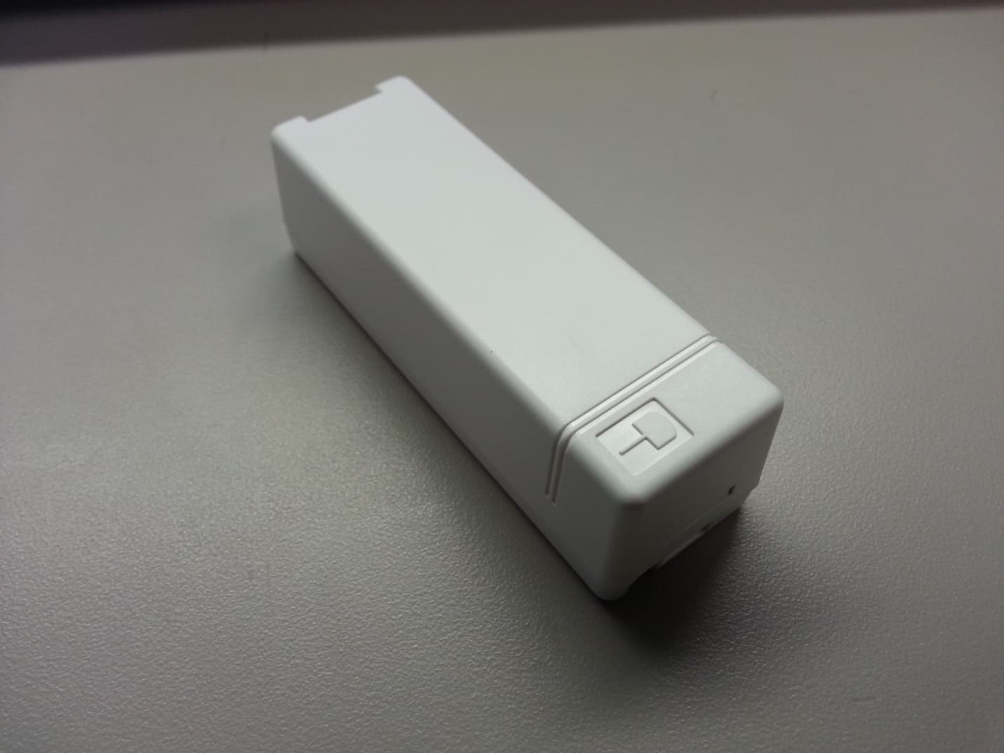
Click to zoom
Application Details
- Equipment Class
- DSC - Part 15 Security/Remote Control Transmitter
- Date of Grant
- Aug 05, 2014
- Application Purpose
- Original Equipment
- Date of Application
- Aug 05, 2014
- Equipment Note
- Door/window Sensors used by Security System
- Frequency Range
- 345.00000000 - 345.00000000
- Company
- Cinch Systems, Inc
- Country
- United States
Documents & Files
Document Text
Text extracted from the exhibit documents filed with the FCC. Open a document above to read the original.
Users Manual
Secure ◄► Simple ◄► State of the Art Installation Instructions Document Number: I-RF-FHW-HW Rev. A July 2104 RF-FHW-HW Wireless Sensor - Freeze, Heat, Water Rev A CINCH Systems, Inc. Page 1 of 2 Part #: RF-FHW-HW (Wireless Freeze, Heat or Water Sensor) Product Summary The Wireless FHW Sensor is compatible with all Honeywell wireless control panels. The device is capable of monitoring three environmental items: Freeze - detects low temperature Heat - detects high temperature Water - detects water Installation: The sensor is designed with a 6 foot cable connecting the water detector to the sensor. If used in a freeze or heat configuration the sensor should be mount as to provide optimum notification for a freeze or heat condition. Wiring: The water detector is pre-wired to the wireless sensor, no other wiring is required Programming: The sensor had a tab in the battery bucket that must be removed before programming See control panel installation instructions for programming references. Specifications: Battery: 3VDC, 1.55Ah, CR123A Lithium Battery Typical Battery Life: Up to 14+ Years External Input Sampling Current: 20 μA Switch Type: Magnasphere Open loop Operating Gap: 0.63 in (1.60 cm) Magnet Type: Neodymium Iron Boron (Rare Earth) Supervisory Interval: 64 minutes Wire Run to External Input: 100 feet (30.5 m) Operating Temperature: 14°F (-10°C) to 140°F (60°C) Enclosure: ABS POLYLAC® PA-717C (UL94 HB flame-rating) Weight: 1.6 oz. (51g) Switch Dimensions: 3.2 in (81.3 mm) L x 1.04 in (26.4 mm) W x .96 in (24.4 mm) H Magnet Dimensions: 1.3 in (33 mm) L x 0.5 in (1.27 mm) H x 0.43 in (10.9 mm) W Color: White or Brown
Users Manual
Secure ◄► Simple ◄► State of the Art Installation Instructions Document Number: I-RF-SDWS-HW Rev. A July 2104 RF-SWDS-HW Wireless Door/Window Sensor Rev A CINCH Systems, Inc. Page 1 of 3 Part #: RF-SDWS-HW (Wireless Door/Window Sensor) - Honeywell compatible Product Summary The Wireless Door/Window Sensor is compatible with all Honeywell wireless control panels. The device is surface mounted and equipped with an internal contact and the capability of using an external contact. A cover tamper doubles as an enrollment switch. Installation: The sensor is designed to mount on the door or window frame and the magnet on the door or window (moving part). Secure ◄► Simple ◄► State of the Art Installation Instructions Document Number: I-RF-SDWS-HW Rev. A July 2104 RF-SWDS-HW Wireless Door/Window Sensor Rev A CINCH Systems, Inc. Page 2 of 3 Wiring: Programming: See control panel installation instructions for programming references. Specifications: Battery: 3VDC, 1.55Ah, CR123A Lithium Battery Typical Battery Life: Up to 14+ Years External Input Sampling Current: 20 μA Switch Type: Reed Open loop Operating Gap: 0.63 in (1.60 cm) Magnet Type: Neodymium Iron Boron (Rare Earth) Supervisory Interval: 64 minutes Wire Run to External Input: 100 feet (30.5 m) Operating Temperature: 14°F (-10°C) to 140°F (60°C) Enclosure: ABS POLYLAC® PA-717C (UL94 HB flame-rating) Weight: 1.6 oz. (51g) Switch Dimensions: 3.2 in (81.3 mm) L x 1.04 in (26.4 mm) W x .96 in (24.4 mm) H Magnet Dimensions: 1.3 in (33 mm) L x 0.5 in (1.27 mm) H x 0.43 in (10.9 mm) W Color: White or Brown
Users Manual
Secure ◄► Simple ◄► State of the Art Installation Instructions Document Number: I-RF-SDWS-MAG-HW Rev. A July 2104 RF-SWDS-MAG-HW Wireless Door/Window Sensor Rev A CINCH Systems, Inc. Page 1 of 3 Part #: RF-SDWS-MAG-HW (Wireless Door/Window Sensor) - Honeywell compatible Product Summary The Wireless Door/Window Sensor is compatible with all Honeywell wireless control panels. The device is surface mounted and equipped with an internal contact and the capability of using an external contact. A cover tamper doubles as an enrollment switch. A tamper-proof sensor reduces the chance of defeating the magnet. Installation: The sensor is designed to mount on the door or window frame and the magnet on the door or window (moving part). Secure ◄► Simple ◄► State of the Art Installation Instructions Document Number: I-RF-SDWS-MAG-HW Rev. A July 2104 RF-SWDS-MAG-HW Wireless Door/Window Sensor Rev A CINCH Systems, Inc. Page 2 of 3 Wiring: Programming: See control panel installation instructions for programming references. Specifications: Battery: 3VDC, 1.55Ah, CR123A Lithium Battery Typical Battery Life: Up to 14+ Years External Input Sampling Current: 20 μA Switch Type: Magnasphere Open loop Operating Gap: 0.63 in (1.60 cm) Magnet Type: Neodymium Iron Boron (Rare Earth) Supervisory Interval: 64 minutes Wire Run to External Input: 100 feet (30.5 m) Operating Temperature: 14°F (-10°C) to 140°F (60°C) Enclosure: ABS POLYLAC® PA-717C (UL94 HB flame-rating) Weight: 1.6 oz. (51g) Switch Dimensions: 3.2 in (81.3 mm) L x 1.04 in (26.4 mm) W x .96 in (24.4 mm) H Magnet Dimensions: 1.3 in (33 mm) L x 0.5 in (1.27 mm) H x 0.43 in (10.9 mm) W Color: White or Brown
External Photos
Model RF-SDWS-HW Top and Rear View Model RF-SDWS-HW Top, Front and Side View Model RF-SDWS-HW Top, Front and Alternate Side View Model RF-SDWS-HW Back View Models RF-SDWS-MAG-HW, MSS-RFS-200, MSS-RFS-300, RF-FHW-HW Top and Rear View Models RF-SDWS-MAG-HW, MSS-RFS-200, MSS-RFS-200, RF-FHW-HW Top, Front and Side View Models RF-SDWS-MAG-HW, MSS-RFS-200, MSS-RFS-200, RF-FHW-HW Top, Front and Alternate Side View Models RF-SDWS-MAG-HW, MSS-RFS-200, MSS-RFS-200, RF-FHW-HW Back View
ID Label/Location Info
Label Samples Labels are UL Listed and utilize permanent adhesive. Tyco P/N WP-040040-10-9 Applied by hand
Internal Photos
Top Models RF-SDWS-HW, RF-SDWS-MAG-HW, RF-FHW-HW Top Parts Removed Models RF-SDWS-HW, RF-SDWS-MAG-HW, RF-FHW-HW Top Model MSS-RFS-200, MSS-RFS-300 Top Parts Removed Model MSS-RFS-200, MSS-RFS-300 Bottom All Models
Test Report
TÜV SÜD AMERICA INC 1775 Old Hwy 8 NW, Suite 104 New Brighton MN 55112-1891 Tel: (651) 638-0297 Fax: (651) 638-0298 Rev. 113006 TEST REPORT FCC Part 15 Subpart C Section 15.231 IC RSS-210 Issue 8 IC RSS-Gen Issue 3 MANUFACTURER'S NAME Cinch Systems Inc 12075 43rd Street NE Suite 300 St Michael MN 55376 PRODUCT NAME Standard Door Window Sensor, Standard DWS- Magnasphere-345 MHz MODEL NUMBER(S) TESTED RF-SDWS-MAG-HW Magnasphere switch version Full test RF-SDWS-HW Reed version - Partial test SERIAL NUMBER(S) TESTED 123456 PRODUCT DESCRIPTION Standard Door Window Sensor - Reed or custom activation switch TEST REPORT NUMBER NC1404002.1 TEST DATE(S) 05-13 June 2014 TÜV SÜD America Inc, as an independent testing laboratory, declares that the equipment tested as specified above conforms to the applicable EMC requirements of FCC Part 15 Subpart C Section 15.231 “Periodic operation in the band 40.66–40.70 MHz and above 70 MHz.” and Industry Canada RSS-210 Issue 8 “Licence-exempt Radio Apparatus (All Frequency Bands): Category I Equipment” and Industry Canada RSS-Gen Issue 3 “General Requirements and Information for the Certification of Radio Apparatus”. It is the manufacturer's responsibility to assure that additional production units of this model are manufactured with identical electrical and mechanical characteristics. Any modifications necessary for compliance made during testing on the above mentioned date(s) must be implemented in all production units for compliance to be maintained. Issue Date: 07 July 2014 Joel T Schneider Greg Jakubowski Senior EMC Engineer Senior EMC Technician Not Transferable FCC ID: 2ABBZ-RF-SDWS-HW IC: 11817A-RFSDWSHW TÜV SÜD AMERICA INC 1775 Old Hwy 8 NW, Suite 104 New Brighton MN 55112-1891 Tel: (651) 638-0297 Fax: (651) 638-0298 Rev. 113006 EMC TEST REPORT Test Report No. NC1404002.1 Date of issue: 07 July 2014 Product Name Standard Door Window Sensor, Standard DWS-Magnasphere-345 MHz Model(s) Tested RF-SDWS-MAG-HW, RF-SDWS-HW Serial No(s) Tested 123456 Product Description Standard Door Window Sensor - Reed or custom activation switch Manufacturer Cinch Systems Inc 12075 43rd Street NE Suite 300 St Michael MN 55376 Test Result Positive Negative TÜV SÜD America Inc reports apply only to the specific samples tested under stated test conditions. It is the manufacturer's responsibility to assure that additional production units of this model are manufactured with identical electrical and mechanical components. TÜV SÜD America Inc shall have no liability for any deductions, inferences or generalizations drawn by the client or others from TÜV SÜD America Inc issued reports. This report is the confidential property of the client. As a mutual protection to our clients, the public and ourselves, extracts from the test report shall not be reproduced except in full without our written approval. TÜV SÜD America’s Wild River Lab maintains A2LA accreditation to ISO/IEC 17025 for the specific tests listed in A2LA Certificate #2955.11 as an Electrical Testing Laboratory. TÜV SÜD America Inc and its professional staff hold government and professional organization certifications and are members of AAMI, ACIL, AEA, ANSI, IEEE, NARTE, and VCCI. Test Report NC1404002.1Page 1 of 23 FCC ID: 2ABBZ-RF-SDWS-HW IC: 11817A-RFSDWSHW TÜV SÜD AMERICA INC 1775 Old Hwy 8 NW, Suite 104 New Brighton MN 55112-1891 Tel: (651) 638-0297 Fax: (651) 638-0298 Rev. 113006 REVISION RECORD REVISION TOTAL NUMBER OF PAGES DATE DESCRIPTION 23 07 July 2014 Initial Release Test Report NC1404002.1Page 2 of 23 FCC ID: 2ABBZ-RF-SDWS-HW IC: 11817A-RFSDWSHW TÜV SÜD AMERICA INC 1775 Old Hwy 8 NW, Suite 104 New Brighton MN 55112-1891 Tel: (651) 638-0297 Fax: (651) 638-0298 Rev. 113006 D I R E C T O R Y Contents Revision Record 3 Directory 4 Test Regulations 4 Environmental Conditions 4 Power Supply 4 Test Equipment Traceability 4 Test Information Radiated Emissions 30 - 3200 MHz FCC 15.231(b), IC RSS-210 A1.1 5 - 8 Occupied Bandwidth FCC 15.231(c), IC RSS-210 A1.1.3 9 - 10 Periodic Operation FCC 15.231(a), IC RSS-210 A1.1.1 11 Test area diagram 12 Test-setup Photos 13 - 14 Equipment Under Test Information 15 General Remarks, Deviations, Summary 16 Appendix A EMC Test Plan and Constructional Data Form 17 - 23 Test Report NC1404002.1Page 3 of 23 FCC ID: 2ABBZ-RF-SDWS-HW IC: 11817A-RFSDWSHW TÜV SÜD AMERICA INC 1775 Old Hwy 8 NW, Suite 104 New Brighton MN 55112-1891 Tel: (651) 638-0297 Fax: (651) 638-0298 Rev. 113006 EMC TEST REGULATIONS: The tests were performed according to the following regulations: FCC Part 15 Subpart C §15.231 IC RSS-210 Issue 8 IC RSS-Gen Issue 3 ENVIRONMENTAL CONDITIONS IN THE LAB Actual Temperature: : 22-23°C Atmospheric pressure : 99kPa Relative Humidity : 45-51% POWER SUPPLY UTILIZED Power supply system : 3 VDC TEST EQUIPMENT All measurement instrumentation is traceable to the National Institute of Standards and Technology and is calibrated according to internal procedure. MEASUREMENT UNCERTAINTY The test system for conducted emissions is defined as the LISN, tuned receiver or spectrum analyzer, and coaxial cable. The test system has a measurement uncertainty of ±1.8 dB. The test system for radiated emissions is defined as the antenna, the pre-amplifier, the spectrum analyzer and the coaxial cable. The test system has a measurement uncertainty of ±4.8 dB. All measurement instrumentation is traceable to the National Institute of Standards and Technology and is calibrated according to internal procedure. SIGN EXPLANATIONS - not applicable - applicable Test Report NC1404002.1Page 4 of 23 FCC ID: 2ABBZ-RF-SDWS-HW IC: 11817A-RFSDWSHW TÜV SÜD AMERICA INC 1775 Old Hwy 8 NW, Suite 104 New Brighton MN 55112-1891 Tel: (651) 638-0297 Fax: (651) 638-0298 Rev. 113006 Radiated Emissions 30 - 1000 MHz FCC 15.231(b), IC RSS-210 A1.1 Test summary The requirements are: - MET - NOT MET Testing was performed in accordance with the test procedure of ANSI C63.4 2009, clause 8.3. Test location Wild River Lab…
Text truncated - open the document above for the full version.
Test Setup Photos
TÜV SÜD AMERICA INC 1775 Old Hwy 8 NW, Suite 104 New Brighton MN 55112-1891 Tel: (651) 638-0297 Fax: (651) 638-0298 Rev. 113006 TEST SETUP FOR EMISSIONS TESTING WILD RIVER LAB Large Test Site Notes: 1. Items shown in dotted lines are located on the floor below the test area. It is 5 meters vertically from the ground floor to the test area. 2. 50 Hz and 60 Hz are power panels for alternating current. 3. The antenna may be positioned horizontally 3 and 10 meters from the center of the turntable. 4. The circle is either a 6.7 meter or 1.2 meter diameter turntable. 5. A ground plane is in the plane of this sheet. 6. The test sample is shown in the azimuthal position representing zero degrees. ANTENNA EUT 0 90 270 180 60 50 Shielded Enclosure Test Report NC1404002.1Page 12 of 23 FCC ID: 2ABBZ-RF-SDWS-HW IC: 11817A-RFSDWSHW TÜV SÜD AMERICA INC 1775 Old Hwy 8 NW, Suite 104 New Brighton MN 55112-1891 Tel: (651) 638-0297 Fax: (651) 638-0298 Rev. 113006 Test-setup photo(s): radiated emissions Test Report NC1404002.1Page 13 of 23 FCC ID: 2ABBZ-RF-SDWS-HW IC: 11817A-RFSDWSHW TÜV SÜD AMERICA INC 1775 Old Hwy 8 NW, Suite 104 New Brighton MN 55112-1891 Tel: (651) 638-0297 Fax: (651) 638-0298 Rev. 113006 Test-setup photo(s): radiated emissions above 1 GHz Test Report NC1404002.1Page 14 of 23 FCC ID: 2ABBZ-RF-SDWS-HW IC: 11817A-RFSDWSHW
Contact Information
Applicant
Joel C Christianson(CEO)
Test Firm
TUV SUD America Inc.Mac Elliott
Technical Specifications
| # | Rule Parts | Frequency Range | Power Output |
|---|---|---|---|
| 1 | 15.231 | 345 MHz - 345 MHz | - |
Other Applications from Cinch Systems, Inc
2ABBZ-RF-ROR-V3-319
Jun 10, 2026RF-ROR-V3-319-NN
Equipment Class
DSC - Part 15 Security/Remote Control Transmitter2ABBZ-RF-ARGB-319V3
Apr 07, 2026Wireless Glass Break Sensor
Equipment Class
DSC - Part 15 Security/Remote Control Transmitter2ABBZ-R-QS5230-840
Dec 01, 2025Wireless CO Detector
Equipment Class
DSC - Part 15 Security/Remote Control Transmitter2ABBZ-RF-CO-319
Nov 25, 2025Wireless CO Detector
Equipment Class
DSC - Part 15 Security/Remote Control Transmitter
2ABBZ-RF-360PIR-433
Jun 28, 2021RF-CPIR-433, CLR-C1-360PIR
Equipment Class
DSC - Part 15 Security/Remote Control Transmitter