2ABD9W880BS1.9GHz Digital Modulation Cordless Base unit
IPN ADDCOM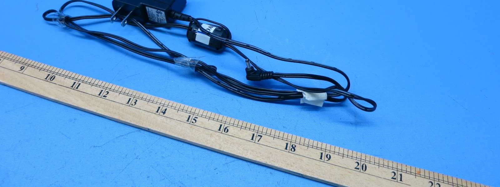
Click to zoom
Application Details
- Equipment Class
- PUB - Part 15 Unlicensed PCS Base Station
- Date of Grant
- Apr 13, 2015
- Application Purpose
- Original Equipment
- Date of Application
- Apr 13, 2015
- Equipment Note
- 1.9GHz Digital Modulation Cordless Base unit
- Frequency Range
- 1921.53600000 - 1924.44800000
- Company
- IPN ADDCOM
- Country
- Netherlands
Documents & Files
Document Text
Text extracted from the exhibit documents filed with the FCC. Open a document above to read the original.
Users Manual
IPN W880 Operation Manual 1 Headset ‘ON/OFF’ LED 2 Headset ‘ON/OFF’ button 3 Power LED 4 Headset charge LED 5 Headset ‘IN USE’ LED 6 Battery LED indicator 7 Microphone volume up 8 Microphone volume down 10 Power socket 11 Handset connector 9 Telephone connector (‘TEL’ port) 13 Wiring switch 14 Receive volume up/down 15 Mute button 16 Battery charging slot 17 Battery remove button 18 Headset registration button 12 Auto answer disable button BEFORE OPERATING THE IPNW880 IMPORTANT SAFETY INSTRUCTIONS PLEASE READ THE ENCLOSED 1 2 15 14 13 16 17 6 5 4 3 18 12 7 8 10 11 9 18 12 6 5 4 3 1 2 15 14 13 16 17 6 5 4 3 18 12 7 8 10 11 9 Contents: 1. Product description 2. Setup 2.1 Connecting to a telephone or ter minal with a headset port 2.2 Connection to a telephone or ter minal without a headset port 2.3 Wearing style 3. Operation 3.1 Making and receiving calls 3.1.1 Making an outgoing call 3.1.2 Receiving an outgoing call 3.2 Adjusting the ring volume 3.3 Muting the headset microphone 3.4 Headset transmitting volume setting 3.5 Adjusting headset receive volume 3.6 Batt ery hotswap 3.7 Batt ery level indication 3.8 Making a confer ence call 3.9 Overview of audio signals 3.10 Register ing a new headset to the base 4. Troubleshooting 1. Product description The Emotion DECT is a fully wireless headset ‘handsfree’ with true wireless mobility. Main features: • DECT wireless headset solution • Convertible into two wearing styles: headband and earhook • Up to 6.5 hours talk time without recharging • Noise cancelling microphone for reduced background noise • Secure high quality audio • Receive volume contr ol on headset • Mute button on headset • Talk button with LED on headset • Range up to 400m • ‘Out of range’ war ning • DECT/GAP compatible • Second batt ery storage/charging point on base 2. Setup • Connect the power adaptor supplied with the product to the base unit (10). The base power LED (3) will light. The little line on the batt ery has to match the line on the batt ery slot, otherwise the batt ery • The headset LED (1) will turn on for about standby mode. recommended that the headset is charged for a minimum of 4 hours before use. 2.1 Connecting to a telephone or ter minal with a headset port • Using the headset cord supplied with the product, connect the ‘TEL’ port (9) on the headset base with the headset port on your telephone. • Use the power adaptor supplied with the product to connect the headset base (10) to a power socket. • You may need to adjust the wiring switch (13) that is located on the side of the headset base 2.2 Connecting to a telephone or ter minal without a headset port • Using the headset cord supplied with the product, connect the ‘TEL’ port (9) on headset base with the ‘handset’ port on your telephone. • Connect the telephone handset cord to the handset (11) port on the headset base. • Use the power adaptor supplied with the product to connect the headset base (10) to a power socket. • You may need to adjust the wiring switch (13) that is located on the side of the headset base 2.4 Wearing style Your Emotion DECT headset is supplied with a headband and an earhook. • Headband This can be attached to the headset to allow for either left or right ear wearing and the size • Earhook This can also be used on either the left or right ear. To remove the headband or earhook: put your thumb on the speaker and carefully pull the headband or earhook with your other hand towar ds you. 3. Operation 3.1 Making and receiving calls 3.1.1 Making an outgoing call • Lift the headset from the base to answer the call. I f you are already wearing the headset press the headset’s ‘ON/OFF’ button (2). The base ‘IN USE’ LED (5) will light. • Dial the telephone number on the telephone ter minal the base or press the ON/OFF button (2) to 3.1.2 Receiving an incoming call • Lift the headset from the base to answer the call. I f you are already wearing the headset press the headset’s ‘ON/OFF’ button (2). The base ‘IN USE’ LED (5) will light. • To end the call, r eplace the headset on the base or press the headset ON/OFF button (2). 3.2 Adjusting the ringing volume When the headset is ringing to indicate an incoming call, you can adjust the ring volume by moving the rocker switch (14) at the back of the headset. 3.3 Muting the headset microphone To mute the headset microphone when on a call, press the mute button (15) on the back of the headset. While the headset is in mute mode, a short beep will be heard on the headset every 8 seconds. Press the Mute button (15) again to release the mute. 3.4 Headset transmitting volume setting During a call you can adjust the transmit volume of the headset by using the two buttons (7 and 8) located on the back of the headset base. 3.5 Adjusting headset receive volume Use the rocker switch (14) at the back of the headset to adjust the receive volume on your headset. You will hear a beep sound for each volume step up or down. 3.6 Battery – hotswap The user can “hotswap” the headset battery while on a call. When the battery is removed from the headset, the base unit will put the call on hold for a maximum of 5 minutes. When the new battery is ¡ tted to the headset, the ‘IN USE’ LED (1) will turn on and the call will be active again. Put the second battery in the battery charging slot (16) on the top side of the base. The battery can be removed by sliding the battery remove button (17) sidewards. 3.7 Battery level indication The four LEDs (6) on the front of the headset base indicate the battery level of your headset battery. IndicationBattery level One LED ¥ ashing< 20% One LED on20%-40% Two LEDs on40%-60% Three LEDs on60%-80% Four LEDs on80%-100% 3.8 Making a conference call Your Emotion DECT headset allows a second headset to be temporarily connected to the base so that you can have a three way conference call. • Setup the call using the primary headset unit. • Once on the call, place the second Emotion DECT headset unit on the base charger. • After about one second, th…
Text truncated - open the document above for the full version.
External Photos
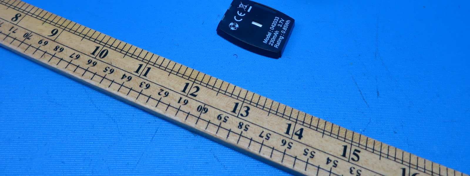
INTERTEK TESTING SERVICES External Photos FCC ID: 2ABD9W880BS external photos - 1 of 3 HK13051652 Job Number HK13051652 Job Number INTERTEK TESTING SERVICES External Photos FCC ID: 2ABD9W880BS external photos - 2 of 3 HK13051652 Job Number HK13051652 Job Number INTERTEK TESTING SERVICES External Photos FCC ID: 2ABD9W880BS external photos - 3 of 3 HK13051652 Job Number HK13051652 Job Number
ID Label/Location Info
FCC ID: 2ABD9W880HS 22.0 mm 4 . 0 m m CM US I.T.E. Intertek 4008039 L I D S T E THIS DEVICE COMPLIES WITH PART 15 OF THE FCC RULES. OPERATION IS SUBJECT TO THE FOLLOWING TWO CONDITIONS: (1) THIS DEVICE MAY NOT CAUSE HARMFUL INTERFERENCE; AND (2) THIS DEVICE MUST ACCEPT ANY INTERFERENCE RECEIVED. INCLUDING INTERFERENCE THAT MAY CAUSE UNDESIRED OPERATION. CM US I.T.E. Intertek 4008039 L I D S T E THIS DEVICE COMPLIES WITH PART 15 OF THE FCC RULES. OPERATION IS SUBJECT TO THE FOLLOWING TWO CONDITIONS: (1) THIS DEVICE MAY NOT CAUSE HARMFUL INTERFERENCE; AND (2) THIS DEVICE MUST ACCEPT ANY INTERFERENCE RECEIVED. INCLUDING INTERFERENCE THAT MAY CAUSE UNDESIRED OPERATION. 3 4 . 0 0 m m 52.00 mm HAC Model No.: IPN W880 FCC ID: 2ABD9W880BS COMPLIES WITH 47 CFR PART 68 REGISTRATION NO.: US: 82HKXNAN880 RINGER EQUIVALENCE: NAN JACK: RJ 9 7.2VDC 500mA HAC Model No.: IPN W880 FCC ID: 2ABD9W880BS COMPLIES WITH 47 CFR PART 68 REGISTRATION NO.: US: 82HKXNAN880 RINGER EQUIVALENCE: NAN JACK: RJ 9 7.2VDC 500mA FCC ID: 2ABD9W880HS
Internal Photos
INTERTEK TESTING SERVICES Internal photos FCC ID: 2ABD9W880BS internal photos - 1 of 8 INTERTEK TESTING SERVICES Internal photos FCC ID: 2ABD9W880BS internal photos - 2 of 8 INTERTEK TESTING SERVICES Internal photos FCC ID: 2ABD9W880BS internal photos - 3 of 8 INTERTEK TESTING SERVICES Internal photos FCC ID: 2ABD9W880BS internal photos - 4 of 8 INTERTEK TESTING SERVICES Internal photos FCC ID: 2ABD9W880BS internal photos - 5 of 8 INTERTEK TESTING SERVICES Internal photos FCC ID: 2ABD9W880BS internal photos - 6 of 8 INTERTEK TESTING SERVICES Internal photos FCC ID: 2ABD9W880BS internal photos - 7 of 8 INTERTEK TESTING SERVICES Internal photos FCC ID: 2ABD9W880BS internal photos - 8 of 8
RF Exposure Info
INTERTEK TESTING SERVICES FCC ID: 2ABD9W880BS RF exposure - 1 of 1 For Maximum Permissible Exposure (MPE) evaluation of the base unit, the maximum power density at 20 cm from this mobile transmitter shall be less than the General Population / Uncontrolled MPE limit in OET Bulletin 65 and meet the requirement listed in KDB447498. For the 1.9GHz Cordless Base Unit of tested model: W880, the measured powers among all the measured channels were within its production tolerance: +19 dBm (Minimum) and +21 dBm (Maximum).The antenna gain of W880 is 0 dBi = 1.00 (num gain) and its maximum source-based time-averaging duty factor is 8.3% (2/24 x100%). From these data and its operating configuration – Mobile device, the exposed power density at a distance (R) of 20cm from the center of radiation of the antenna can be calculated according to OET Bulletin 65 as follow: The Conducted Power = 21 dBm = 125.9 mW The Conducted Power source-based time-averaging output power = (125.9 * 0.083) mW = 10.45 mW The power density at 20cm = 10.45 *1.00/ 4R 2 = 0.0021 mW cm -2 In the frequency range of 1,500 - 100,000MHz, the MPE limit is 1.0 mWcm -2 for general population and uncontrolled exposure. As the measured power density at 20cm from the transmitter is lower than the MPE limit, the compliance to the MPE limit can be ensured by indicating the minimum 20cm separation between the transmitter's radiating structures and body of the user or nearby persons. The following RF exposure statement is proposed to be included in the user manual: “ FCC RF Radiation Exposure Statement Caution: To maintain compliance with the FCC’s RF exposure guidelines, place the base unit at least 20cm from nearby persons.”
Test Report
- Intertek’s standard Terms and Conditions can be obtained at our website: http://www.intertek.com/terms/. - The test report only allows to be revised within the retention period unless further standard or the requirement was noticed. - This report is for the exclusive use of Intertek's Client and is provided pursuant to the agreement between Intertek and its Client. Intertek's responsibility and liability are limited to the terms and conditions of the agreement. Intertek assumes no liability to any party, other than to the Client in accordance with the agreement, for any loss, expense or damage occasioned by the use of this report. Only the Client is authorized to permit copying or distribution of this report and then only in its entirety. Any use of the Intertek name or one of its marks for the sale or advertisement of the tested material, product or service must first be approved in writing by Intertek. The observations and test results in this report are relevant only to the sample tested. This report by itself does not imply that the material, product, or service is or has ever been under an Intertek certification program. Intertek Testing Services Hong Kong Ltd. 2/F., Garment Centre, 576 Castle Peak Road, Kowloon, Hong Kong. Tel: (852) 2173 8888 Fax: (852) 2785 5487 Website: www.hk.intertek-etlsemko.com TEST REPORT Report Number: 13051652HKG-001 Application For Original Grant of 47 CFR Part 15 Certification Unlicensed Personal Communication Service Devices FCC ID: 2ABD9W880BS Prepared and Checked by: Approved by: Signed on File Jess Tang Nip Ming Fung, Melvin Lead Engineer Assistant Manager June 16, 2014 INTERTEK TESTING SERVICES Test Report Number: 13051652HKG-001 Page 1 of 57 FCC ID: 2ABD9W880BS GENERAL INFORMATION Applicant Name: IPN ADDCOM Applicant Address: Bijsterhuizen 2414, 6604 LL Wijchen, The Netherlands FCC Specification Standard: FCC Part 15, October 1, 2012 Edition FCC ID: 2ABD9W880BS FCC Model(s): W880, W860, AD670, AD680 Type of EUT: Unlicensed Personal Communications Service Devices Description of EUT: 1.9GHz Digital Modulation Cordless Base unit Serial Number: N/A Sample Receipt Date: May 30, 2013 Date of Test: June 20, 2013 to July 31, 2013 Report Date: June 16, 2014 Environmental Conditions: Temperature: +10 to 40°C Humidity: 10 to 90% INTERTEK TESTING SERVICES Test Report Number: 13051652HKG-001 Page 2 of 57 FCC ID: 2ABD9W880BS Table of Contents 1.0 Test Results Summary & Statement of Compliance.............................................. 5 1.1 Summary of Test Results ....................................................................................... 5 1.2 Statement of Compliance ....................................................................................... 6 2.0 General Description................................................................................................. 8 2.1 Product Description ................................................................................................. 8 2.2 Technical Description .............................................................................................. 8 2.3 Test Methodology.................................................................................................... 8 2.3 Test Facility............................................................................................................. 8 3.0 System Test Configuration.................................................................................... 10 3.1 Justification ........................................................................................................... 10 3.2 Conducted Emission Test Configuration ................................................................ 11 3.3 Conducted Monitoring and Operational Test Configuration .................................... 11 3.4 EUT Exercising Software....................................................................................... 11 3.5 Details of EUT and Description of Accessories...................................................... 12 3.6 Measurement Uncertainty ..................................................................................... 12 4.0 Measurement Results............................................................................................ 14 4.1 Antenna Requirement........................................................................................... 14 4.2 Digital Modulation Techniques............................................................................... 14 4.3 Emission Bandwidth.............................................................................................. 15 4.4 Directional Gain of the Antenna ............................................................................. 17 4.5 Peak Transmit Power ............................................................................................ 18 4.6 Power Spectral Density ......................................................................................... 20 4.7 Automatic Discontinuation of Transmission............................................................ 22 4.8 Unwanted Emission Inside the Sub-Band .............................................................. 23 4.9 Emissions Outside the Sub-Band .......................................................................... 25 4.9.1 Radiated Emissions Configuration Photographs ................................................. 26 4.9.2 Radiated Emissions Data ................................................................................... 26 4.9.3 Field Strength Calculation................................................................................... 32 4.9.4 Average Factor Calculation and Transmitter ON Time Measurements ................ 33 4.10 AC Power Line Conducted Emissions ................................................................. 34 4.10.1 AC Power Line Conducted Emissions Configuration Photographs .................... 35 4.10.2 AC Power Line Conducted Emissions D…
Text truncated - open the document above for the full version.
Test Report
headset headset M L declared by manufacturer is 30dB. NA NA NA B B
Test Setup Photos
INTERTEK TESTING SERVICES The Worst Case Configuration Photographs - Mode: Transmission FCC ID: 2ABD9W880BS config photos (radiated emission - base unit) - 1 of 1 Radiated Emission - Base Unit Front View Rear View INTERTEK TESTING SERVICES The Worst Case Configuration Photographs - Mode: Talk FCC ID: 2ABD9W880BS config photos (conducted emission) - 1 of 2 Conducted Emission Front View Right Side View INTERTEK TESTING SERVICES The Worst Case Configuration Photographs - Mode: Talk FCC ID: 2ABD9W880BS config photos (conducted emission) - 2 of 2 Conducted Emission Left Side View
Contact Information
Applicant
Sander Derksen
Technical Contact
Intertek Testing Services Hong Kong Ltd.Melvin Nip
[email protected](852) 2173 8888
Flat D, 5/F., Garment Centre · Kowloon · Hong Kong
Non-Technical Contact
Intertek Testing Services Hong Kong Ltd.Melvin Nip
[email protected](852) 2173 8888
Test Firm
Intertek Testing Services Hong KongBilly Chow
Technical Specifications
| # | Rule Parts | Frequency Range | Power Output |
|---|---|---|---|
| 1 | 15D | 1.92 GHz - 1.92 GHz | 97.00 mW |
Other Applications from IPN ADDCOM
2ABD9W880HS
Apr 13, 20151.9GHz Digital Modulation Cordless Headset
Equipment Class
PUE - Part 15 Unlicensed PCS portable Tx held to ear