2ABDO-A003SSmart power bank
Amber Innovation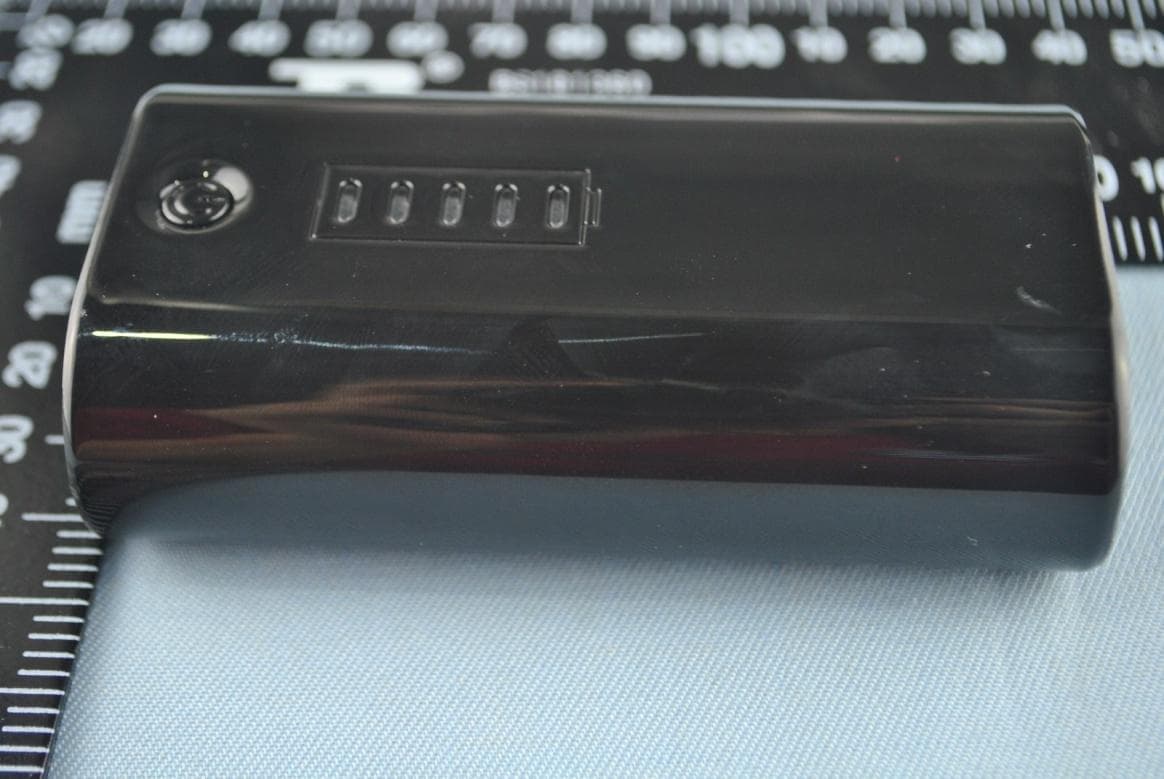
Click to zoom
Application Details
- Equipment Class
- DTS - Digital Transmission System
- Date of Grant
- Dec 01, 2013
- Application Purpose
- Original Equipment
- Date of Application
- Dec 01, 2013
- Equipment Note
- Smart power bank
- Frequency Range
- 2402.00000000 - 2480.00000000
- Company
- Amber Innovation
- Country
- China
Documents & Files
Document Text
Text extracted from the exhibit documents filed with the FCC. Open a document above to read the original.
Users Manual
A003S User’s Manual A003S is a smart power bank. It has 4200mAh Li-ion rechargeable battery and could be used to charge your mobile phone or other electronic devices when their batteries are low. It is also a Bluetooth Low Energy proximity tag. It could connect with your mobile phone through Bluetooth Low Energy. When A003S is separated from your mobile phone, both sides will generate sound alert. Charge other device Plug in the charging cable of your mobile phone into the output socket. Press the button once and it will start to charge your phone. Charge itself Plug in the accompanied cable into the input socket. Plug the other end to any power source which has USB port. A blue led will start to flash once it starts to charge. When the charge is complete the led will stop flashing. Turn on the torch Hold the button until you see the torch is on. Hold the button again until the torch is off. Turn on the Bluetooth® Before you connect your phone with A003S through Bluetooth®, you need to wake up the Bluetooth in A003S. You just flip A003S and you will see a blue led flashing. FCC Information This device complies with Part 15 of the FCC rules. Operation is subject to the following two conditions: (1) this device may not cause harmful interference, and (2) this device must accept any interference received; including interference that may cause undesired operation. Federal Communications Commission (FCC) Statement This Equipment has been tested and found to comply with the limits for a Class B digital device, pursuant to Part 15 of the FCC rules. These limits are designed to provide reasonable protection against harmful interference in a residential installation. This equipment generates, uses and can radiate radio frequency energy and, if not installed and used in accordance with the instructions, may cause harmful interference to radio communications. However, there is no guarantee that interference will not occur in a particular installation. If this equipment does cause harmful interference to radio or television reception, which can be determined by turning the equipment off and on, the user is encouraged to try to correct the interference by one or more of the following measures: - Reorient or relocate the receiving antenna. - Increase the separation between the equipment and receiver. - Connect the equipment into an outlet on a circuit different from that to which the receiver is connected. - Consult the dealer or an experienced radio/TV technician for help. Warning: Changes or modifications to this unit not expressly approved by the party responsible for compliance could void the user authority to operate the equipment. Tested to comply with FCC standard. FOR HOME OR OFFICE USE. Warning : This equipment complies with FCC RF radiation exposure limits set forth for an uncontrolled environment. & This device and its antenna(s) must not be co-located or conjunction with any other antenna or transmitter LED Torch Power Input Output button
Cover Letter(s)
Amber Innovation 1301, No.271 Hushu South Rd.,HangZhou,ZheJiang,China Date: 11/22/2013 BABT TCB Forsyth House, Churchfield Road, Walton-on-Thames, Surrey, KT12 2TD Dear Sir or Madam, We, Amber Innovation hereby authorize Apollo Liu (Ke Mei Ou Laboratory Co., Ltd.) to act as our agent in all matters relating to applications for equipment authorization, including the signing of all documents relating to these matters. This authorization expires on (11/14/2013 to 11/14/2014). Sincerely, Yours sincerely, Company Officer: Jie Liu
Cover Letter(s)
Amber Innovation 1301, No.271 Hushu South Rd.,HangZhou,ZheJiang,China Date: 11/22/2013 BABT TCB Forsyth House, Churchfield Road, Walton-on-Thames, Surrey, KT12 2TD Confidentiality Request FCC ID: 2ABDO-A003S Pursuant to Sections 0.457(d)(1)(ii) and 0.459 of the Commission’s Rules, Amber Innovation hereby requests permanent confidential treatment of information accompanying this application as outlined below: Schematics Block Diagrams Theory of Operation The above materials contain trade secrets and proprietary information not customarily released to the public. The public disclosure of these matters might be harmful to the Applicant and provide unjustified benefits to its competitors. The Applicant understands that pursuant to Rule 0.457(d)(1)(ii), disclosure of this Application and all accompanying materials will not be made before the date of the Grant for this Application. Yours sincerely, Company Officer: Jie Liu
Cover Letter(s)
1 / 1 E506, 5th Floor, No.39 Keji Middle 2nd Rd, Science & Technology Park, Nanshan District, Shenzhen, P. R. China Tel: + 86 755 83642690 Fax: + 86 755 83297077 www.kmolab.com November 22, 2013 Test Lab Attestation Letter This attestation is to confirm that the below listed device was tested at our Test Facilities located at: Test Lab Name: Ke Mei Ou Laboratory Co., Ltd. Test Lab Address: E506, 5th Floor, No.39 Keji Middle 2nd Rd, Science & Technology Park, Nanshan District, Shenzhen, P. R. China Test Lab Registration Number: 962205 Date of Test: October 21~November 4, 2013 Test Report Number: KSZ2013092301J02 Application Name: Amber Innovation FCC ID: 2ABDO-A003S Name of Engineer(s) Performing Test: Eric Guo Company Name of Engineer(s) Performing Test: Ke Mei Ou Laboratory Co., Ltd. TEST LABORATORY: Signature of Authorized Representative of the Test Laboratory: Full Contact Name: Apollo Liu Position/Title: General Manager
External Photos
EUT top view EUT bottom view
ID Label/Location Info
This device complies with Part 15 of the FCC Rules. Operation is subject to the following two conditions: (1) this device may not cause harmful interference, and (2) this device must accept any interference received, including interference that may cause undesired operation. Proposed Label Location on EUT EUT Bottom View/Proposed FCC ID Label Location FCC ID: 2ABDO-A003S FCC ID: 2ABDO-A003S
Internal Photos
EUT inside whole view Main board component side Main board solder side
Test Report
The test report consists 33 pages in total. It may be duplicated completely for legal use with the allowance of the applicant. It shall not be reproduced except in full, without the written approval of Ke Mei Ou Laboratory Corporation. The test result in the report only applied to the tested sample. FCC TEST REPORT Under FCC 15 Subpart C, Paragraph 15.247 Operating in 2400 ~ 2483.5 MHz Band Prepared For : Amber Innovation 1301, No.271 Hushu South Rd.,HangZhou,ZheJiang,China FCC ID: 2ABDO-A003S EUT: Smart power bank Model:A003S November 4, 2013 Issue Date: Original Report Report Type: Test Engineer: Eric Guo Review By: Apollo Liu / Manager Ke Mei Ou Laboratory Co., Ltd. E506, 5th Floor, No.39 Keji Middle 2nd Rd, Science & Technology Park, Nanshan District, Shenzhen, P. R. China Tel: + 86 755 83642690 Fax: + 86 755 83297077 www.kmolab.com Amber Innovation FCC ID: 2ABDO-A003S KMO FCC ID Report Report #: KSZ2013092301J02 Page 2 of 33 TABLE OF CONTENTS 1. General Information ........................................................................................................................................................... 3 1. 1 Notes ............................................................................................................................................................................... 3 1. 2 Testing Laboratory .......................................................................................................................................................... 3 1. 3 Details of Applicant ........................................................................................................................................................ 3 1. 4 Application Details ......................................................................................................................................................... 3 1. 5 Test Item ......................................................................................................................................................................... 3 1. 6 Test Standards ................................................................................................................................................................. 3 2. Technical Test ....................................................................................................................................................................... 4 2. 1 Summary of Test Results ................................................................................................................................................ 4 2. 2 Antenna Requirement ..................................................................................................................................................... 4 3. EUT Modifications .............................................................................................................................................................. 4 4. Conducted Power Line Test ................................................................................................................................................ 5 4. 1 Test Equipment ............................................................................................................................................................... 5 4. 2 Test Procedure ................................................................................................................................................................ 5 4. 3 Test Setup ....................................................................................................................................................................... 5 4. 4 Configuration of the EUT ............................................................................................................................................... 6 4. 5 EUT Operating Condition ............................................................................................................................................... 8 4. 6 Conducted Power Line Emission Limits ........................................................................................................................ 8 4. 7 Conducted Power Line Test Result ................................................................................................................................. 9 5. FCC Part 15.247 Requirements for DTS Systems .......................................................................................................... 10 5. 1 Test Equipment ............................................................................................................................................................. 10 5. 2 Test Procedure .............................................................................................................................................................. 10 5. 3 Test Setup ..................................................................................................................................................................... 10 5. 4 Configuration of the EUT ............................................................................................................................................. 10 5. 5 EUT Operating Condition ............................................................................................................................................. 10 5. 6 Limit ..............................................................................................................................................................................11 5. 7 Test Result .....................................................................................................................................................................11 6. Transmitter Spurious Radiated Emission at 3 Meters .................................................................................................... 20 6. 1 Test Equipment ............…
Text truncated - open the document above for the full version.
Test Setup Photos
Radiated emission test view
Contact Information
Applicant
JIE LIU(CEO)
Test Firm
Ke Mei Ou Laboratory Co., Ltd.Apollo Liu
Technical Specifications
| # | Rule Parts | Frequency Range | Power Output |
|---|---|---|---|
| 1 | 15C | 2.40 GHz - 2.48 GHz | 1.88 mW |
Other Applications from Amber Innovation
2ABDO-A001
Nov 26, 2013Proximity Tag
Equipment Class
DTS - Digital Transmission System