2ABFL105TAGPersonal RFID Tag
Itronik interconnect Ltd.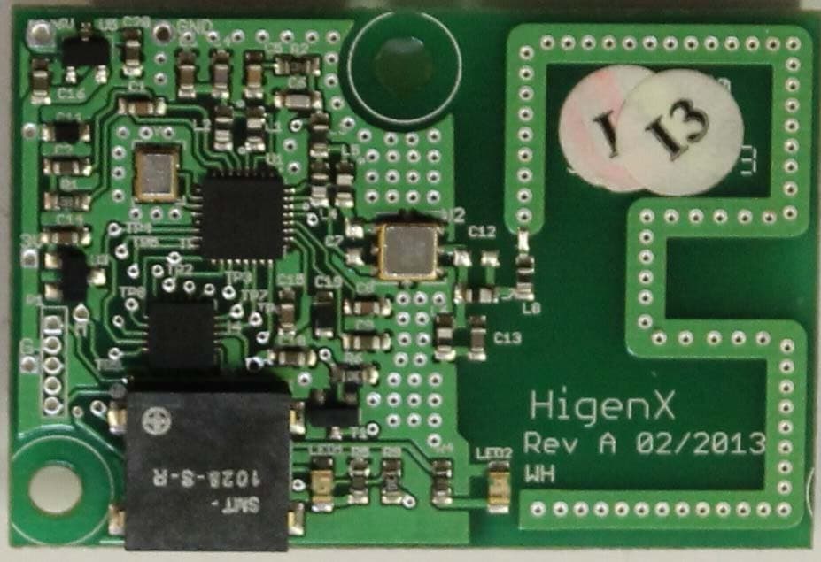
Click to zoom
Application Details
- Equipment Class
- DSR - Part 15 Remote Control/Security Device Transceiver
- Date of Grant
- Apr 29, 2014
- Application Purpose
- Original Equipment
- Date of Application
- Apr 28, 2014
- Equipment Note
- Personal RFID Tag
- Frequency Range
- 434.09900000 - 434.09900000
- Company
- Itronik interconnect Ltd.
- Country
- Ireland
Documents & Files
Document Text
Text extracted from the exhibit documents filed with the FCC. Open a document above to read the original.
Users Manual
Higenx Technical Guide i HP Higenx Technical User Guide 1 December 2013 Higenx, Castleboy, Kilchreest, Loughrea, Co. Galway, Ireland Phone: +353 (0) 91-840016 Email: [email protected] Higenx Technical User Guide 1 Preface Audience This document is intended for anyone involved in the installation and/or maintenance of HigenX hand-hygiene systems. Product Support Product support and answers to any questions about the content of this document can be obtained by contacting Support at: HigenX, Castleboy, Kilchreest, Loughrea, Co. Galway, Ireland Phone: +353 (0) 91-840016 Email: [email protected] Higenx Technical User Guide 2 Contents Preface ............................................................................................................................................ 1 Audience...................................................................................................................................... 1 Product Support .......................................................................................................................... 1 Contents .......................................................................................................................................... 2 System Overview ............................................................................................................................ 5 The Higenx Personal Tag ............................................................................................................... 6 Overview .................................................................................................................................. 6 Logging in: ............................................................................................................................... 6 Usage after Login: ................................................................................................................... 7 Logging out: ............................................................................................................................. 7 Note on Logging in/out: ........................................................................................................... 9 Non-compliance warnings: ...................................................................................................... 9 The different Tag states .......................................................................................................... 9 Replacing the Personal Tag batteries ...........................................Error! Bookmark not defined. The Higenx Register Unit.............................................................................................................. 10 Overview ................................................................................................................................ 10 Using the Register Unit .........................................................................................................10 Setting up and location of Higenx Register Unit ................................................................... 12 The Higenx Zone Control unit....................................................................................................... 15 Overview ................................................................................................................................ 15 Placing the Zone Control unit ................................................................................................ 15 Setting up the Zone Control unit: .......................................................................................... 17 The Higenx Dispenser .................................................................................................................. 19 Overview ................................................................................................................................ 19 Using a dispenser .................................................................................................................. 19 Setting up the Higenx dispenser ........................................................................................... 19 Maintaining the manual dispenser ........................................................................................ 20 Automatic Dispensers ............................................................................................................... 21 Higenx Data Collection ................................................................................................................. 22 Overview.................................................................................................................................... 22 Higenx Technical User Guide 3 Methods of data collection ........................................................................................................ 22 Data Collection with GSM enabled Higenx Register Unit ............................................................ 22 Automatic data collection via a permanently connected PC ................................................ 23 Manual Data Collection................................................................................................................. 24 Manual downloads by customer............................................................................................ 24 Collecting the data ................................................................................................................. 24 Installation Instructions for Higenx manual data collection software ........................................... 28 Technical Specifications ...................................................................................................................i Device address assignment in HigenX system ...............................................................................ii Higenx Technical User Guide 4 Regulatory Statements for FCC and Industry of Canada s: FCC ID: 2ABFL1…
Text truncated - open the document above for the full version.
Cover Letter(s)
THIS MUST BE SIGNED BY THE APPLICANT AND SHOULD BE PLACED ON APPLICANTS LETTERHEAD ONLY IF AGENT IS SUBMITTING APPLICATION 022311 – 6 Itronik Interconnect Ltd. Cloughaun, Kilchreest, Loughrea Co. Galway VAT NUMBER: IE 6409285B Directors ; Mike Mahony, Frank Boyle Co. Reg no; 389285 353 91 840055, Fax 353 91 840007 Authority to Act as Agent Date: _29November 2013 American Certification Body, Inc. 6731 Whittier Avenue Suite C110 McLean, VA 22101 To Whom It May Concern: Compliance Engineering Ireland _____ is authorized to act on our behalf, until otherwise notified, for applications to American Certification Body, Inc. (ACB). We certify that we are not subject to denial of federal benefits, that includes FCC benefits, pursuant to Section 5301 of the Anti-Drug Abuse Act of 1988, 21 U.S.C. 862. Further, no party, as defined in 47 CFR 1.2002 (b), to the application is subject to denial of federal benefits, that includes FCC benefits. Thank you, Agency Agreement Expiration Date: _____(29 November 2014)_____ By: _____Mike Mahony_______________ (Signature 1 ) (Print name) Title: Managing Director On behalf of: Itronik Interconnect Ltd__________________________ (Company Name) Telephone: 0035391 840055__________________________ 1 - Must be signed by applicant contact given for applicant on the FCC site, or by the authorized agent if an appropriate authorized agent letter has been provided. Letters should be placed on appropriate letterhead. THIS MUST BE SIGNED BY THE APPLICANT/AGENT AND SHOULD BE PLACED ON APPROPRIATE LETTERHEAD 022311 – 6 Request for Confidentiality Date: _____29 November 2013___ Subject: Confidentiality Request for: ______2ABFL105TAG______ 11591A-105TAG Pursuant to FCC 47 CRF 0.457(d) and 0.459 and IC RSP-100, Section 10, the applicant requests that a part of the subject FCC application be held confidential. Type of Confidentiality Requested Exhibit Short Term x Permanent Block Diagrams Short Term External Photos Short Term Permanent* 2 Internal Photos Short Term x Permanent Operation Description/Theory of Operation Short Term x Permanent Parts List & Placement/BOM Short Term Permanent Tune-Up Procedure Short Term x Permanent Schematics Short Term Test Setup Photos Short Term Permanent* User’s Manual *Note: ______(Insert Explanation as Necessary)______ ______Itronik interconnect Ltd.______ has spent substantial effort in developing this product and it is one of the first of its kind in industry. Having the subject information easily available to "competition" would negate the advantage they have achieved by developing this product. Not protecting the details of the design will result in financial hardship. Permanent Confidentiality: The applicant requests the exhibits listed above as permanently confidential be permanently withheld from public review due to materials that contain trade secrets and proprietary information not customarily released to the public. Short-Term Confidentiality: The applicant requests the exhibits selected above as short term confidential be withheld from public view for a period of ___(specify number of days not to exceed 180 ) 3 ___ days from the date of the Grant of Equipment Authorization and prior to marketing. This is to avoid premature release of sensitive information prior to marketing or release of the product to the public. Applicant is also aware that they are responsible to notify ACB in the event information regarding the product or the product is made available to the public. ACB will then release the documents listed above for public disclosure pursuant to FCC Public Notice DA 04-1705. NOTE for Industry Canada Applications: The applicant understands that until such time that IC distinguishes between Short Term and Permanent Confidentiality, either type of marked exhibit above will simply be marked Confidential when submitted to IC. Sincerely, By: _____Mike Mahony_______________ (Signature 4 ) (Print name) 2 - The asterisked items (*) require further justification before permanent confidentiality will be allowed. These also currently require review by the FCC under their Permit-But-Ask policy before the grant is issued and can delay completion of an application. Further justification should be added to the note above. One such example for a potted device would be: “The EUT is FULLY potted using a non-removable epoxy based material. Removal of potting material causes irreparable damage to internal circuitry. See photographs exhibits that outline the device before and after potting.” 3 - Please refer to http://acbcert.com/documents/misc-docs/Memo-Short-Term-Vs-Standard-Confidentiality.pdf for complete details. 4 - Must be signed by applicant contact given for applicant on the FCC site, or by the authorized agent if an appropriate THIS MUST BE SIGNED BY THE APPLICANT/AGENT AND SHOULD BE PLACED ON APPROPRIATE LETTERHEAD 022311 – 6 authorized agent letter has been provided. Letters should be placed on appropriate letterhead.
Cover Letter(s)
Higenx compliance statement for Modular Transmitters (in Blue below) § 15.212 Modular transmitters. (a) Single modular transmitters consist of a completely self-contained radiofrequency transmitter device that is typically incorporated into another product, host or device. Split modular transmitters consist of two components: a radio front end with antenna (or radio devices) and a transmitter control element (or specific hardware on which the software that controls the radio operation resides). All single or split modular transmitters are approved with an antenna. All of the following requirements apply, except as provided in paragraph (b) of this section. (1) Single modular transmitters must meet the following requirements to obtain a modular transmitter approval. (i) The radio elements of the modular transmitter must have their own shielding. The physical crystal and tuning capacitors may be located external to the shielded radio elements. Shielding not present ->Non Comply (ii) The modular transmitter must have buffered modulation/data inputs (if such inputs are provided) to ensure that the module will comply with part 15 requirements under conditions of excessive data rates or over-modulation. Comply (iii) The modular transmitter must have its own power supply regulation. Comply (iv) The modular transmitter must comply with the antenna and transmission system requirements of §§ 15.203, 15.204(b) and 15.204(c). The antenna must either be permanently attached or employ a “unique” antenna coupler (at all connections between the module and the antenna, including the cable). The “professional installation” provision of § 15.203 is not applicable to modules but can apply to limited modular approvals under paragraph (b) of this section. Antenna is pcb track ->Comply (v) The modular transmitter must be tested in a stand-alone configuration, i.e. , the module must not be inside another device during testing for compliance with part 15 requirements. Unless the transmitter module will be battery powered, it must comply with the AC line conducted requirements found in § 15.207. AC or DC power lines and data input/output lines connected to the module must not contain ferrites, unless they will be marketed with the module (see § 15.27(a)). The length of these lines shall be the length typical of actual use or, if that length is unknown, at least 10 centimeters to insure that there is no coupling between the case of the module and supporting equipment. Any accessories, peripherals, or support equipment connected to the module during testing shall be unmodified and commercially available (see § 15.31(i)). Comply (vi) The modular transmitter must be equipped with either a permanently affixed label or must be capable of electronically displaying its FCC identification number. Permanently affixed label fitted -> Comply (A) If using a permanently affixed label, the modular transmitter must be labeled with its own FCC identification number, and, if the FCC identification number is not visible when the module is installed inside another device, then the outside of the device into which the module is installed must also display a label referring to the enclosed module. This exterior label can use wording such as the following: “Contains Transmitter Module FCC ID: XYZMODEL1” or “Contains FCC ID: XYZMODEL1.” Any similar wording that expresses the same meaning may be used. The Grantee may either provide such a label, an example of which must be included in the application for equipment authorization, or, must provide adequate instructions along with the module which explain this requirement. In the latter case, a copy of these instructions must be included in the application for equipment authorization. Comply (B) If the modular transmitter uses an electronic display of the FCC identification number, the information must be readily accessible and visible on the modular transmitter or on the device in which it is installed. If the module is installed inside another device, then the outside of the device into which the module is installed must display a label referring to the enclosed module. This exterior label can use wording such as the following: “Contains FCC certified transmitter module(s).” Any similar wording that expresses the same meaning may be used. The user manual must include instructions on how to access the electronic display. A copy of these instructions must be included in the application for equipment authorization. Electronic Display for FCC ID not used ->N/A (vii) The modular transmitter must comply with any specific rules or operating requirements that ordinarily apply to a complete transmitter and the manufacturer must provide adequate instructions along with the module to explain any such requirements. A copy of these instructions must be included in the application for equipment authorization. Comply (viii) The modular transmitter must comply with any applicable RF exposure requirements in its final configuration. Comply (2) Split modular transmitters must meet the requirements in paragraph (a)(1) of this section, excluding paragraphs (a)(1)(i) and (a)(1)(v), and the following additional requirements to obtain a modular transmitter approval. Not split module -> N/A (i) Only the radio front end must be shielded. The physical crystal and tuning capacitors may be located external to the shielded radio elements. The interface between the split sections of the modular system must be digital with a minimum signaling amplitude of 150 mV peak-to- peak. Not split module -> N/A (ii) Control information and other data may be exchanged between the transmitter control elements and radio front end. Not split module -> N/A iii) The sections of a split modular transmitter must be tested installed in a host device(s) similar to that which is representative of the platform(s) intended for use. Not split module -> N/A (iv) Manufacturers must ensure that only transmitter control elements and radio front en…
Text truncated - open the document above for the full version.
Cover Letter(s)
Manufacturer control of unit once in the field: The TAG module shall be limited to use within the Itronik product range :‐ namely Zone Control Unit, Tag unit Dispenser unit. The TAG module will be preinstalled at the manufacturer site for each of these units. These units cannot be modified by the end user. Installers will receive training from a representative of Itronik .
External Photos
Tag pcb photo Front Tag pcb photo Rear
ID Label/Location Info
Tag labels a) Module b) Label dimensions 25MM by 10MM c) Location of the label at the back of the pcb. Tag labels d) when fitted in Dispenser ,or Zone or Tag plastics e) Label dimensions 25MM by 55MM for Dispenser, or Zone f) Label dimensions 25MM by 10MM for Tag plastics g) Location of the label at the side of the enclosure for Dispenser, or Zone h) Location of the label at the back of the pcb. for Tag plastics Itronik MODEL: 105TAG FCC ID : 2ABFL105TAG IC : 11591A-105TAG CONTAINS FCC ID : 2ABFL105TAG IC : 11591A-105TAG
Internal Photos
Tag pcb photo Front Tag pcb photo Rear
Test Report
Report Ref: 13E4815-1b Page 1 of 23 Project Number: 13E4815-1b Prepared for: Itronik Interconnect Ltd. By Compliance Engineering Ireland Ltd Clonross Lane Derrockstown Dunshaughlin Co. Meath FCC Site Registration: 92592 Industry Canada Assigned Site Code: 8517A-2 FCC ID: 2ABFL105TAG IC: 11591A-105TAG Date 25 th April 2014 FCC EQUIPMENT AUTHORISATION Test Report EUT Description RFID Tag pcb module Authorised : John McAuley Compliance Engineering Ireland Ltd Clonross Lane, Derrockstown, Dunshaughlin, Co. Meath Tel: +353 1 8256722 Fax: +353 1 8256733 Report Ref: 13E4815-1b Page 2 of 23 TEST SUMMARY The equipment complies with the requirements according to the following standards. FCC Part Section(s) RSS-210 Section TEST PARAMETERS Test Result 15.231(a) A1.1.1(a) MAXIMUM MODULATION PERCENTAGE (M%) PASS 15.231(b) A.1.1.2(1) RADIATED EMISSIONS PASS 15.231(c) A1.1.3 20dB BANDWIDTH PASS THIS REPORT SHALL NOT BE REPRODUCED EXCEPT IN FULL, WITHOUT THE WRITTEN APPROVAL OF COMPLIANCE ENGINEERING IRELAND LTD Report Ref: 13E4815-1b Page 3 of 23 Exhibit A – Technical Report Table of Contents 1.0 EUT DESCRIPTION..............................................................................................................................4 1.1 EUT OPERATION..................................................................................................................................5 1.2 MODIFICATIONS...................................................................................................................................5 1.3 DATE OF TEST......................................................................................................................................5 1.4.1 MEASUREMENT UNCERTAINTY........................................................................................................6 2.0 EMISSIONS MEASUREMENTS............................................................................................................7 2.1 CONDUCTED EMISSIONS MEASUREMENTS...................................................................................7 2.2 RADIATED EMISSIONS MEASUREMENTS.......................................................................................7 2.3 TEST CRITERIA.....................................................................................................................................9 3.0 MAXIMUM MODULATION PERCENTAGE (M%)..............................................................................11 4.0 FIELD STRENGTH OF SPURIOUS RADIATED EMISSIONS..........................................................14 5.0 LIST OF TEST EQUIPMENT...............................................................................................................18 Report Ref: 13E4815-1b Page 4 of 23 1.0 EUT Description The EUT was a module using a short range 433 MHz band transceiver for RFID communication. Model: 105TAG Type: RFID unit FCC ID: 2ABFL105TAG Company: Itronik Interconnect Ltd. Contact Christopher Slattery Address: Itronik Interconnect Ltd Cloughaun,Kilchreest Loughrea, Co. Galway, Ireland Phone: +353921840055 e-mail: [email protected] Test Standards: 47 CFR, Part 15.231(a,e) Type of radio: Stand-alone Transmitter Type: FSK Operating Frequency Range(s): 434.099 MHz Number of Channels: One Antenna: Integral Transmitter power configuration: 3 v Battery. Oper. Temp Range: 5° C to +35° C Classification: DSR Test Methodology: Measurements performed according to the procedures in ANSI C63.4-2003 ANSI C63.10-2009 Report Ref: 13E4815-1b Page 5 of 23 1.1 EUT Operation Operating Conditions during Test: The equipment under test was operated during the measurement under the following conditions: The EUT was battery powered. The EUT was operated in normal operation mode for duty cycle test. In this mode the EUT was triggered to transmit by bringing a magnet close to it. For all other tests, the EUT was operated in a test mode, where the EUT transmitted (duty cycle with Ton of 50uS and Toff of 30uS ) in continuous modulated mode. Environmental conditions During the measurement the environmental conditions were within the listed ranges: Normal Temperature: +15 to +35 ° C Humidity: 20-75 % 1.1 Modifications No modifications were required in order to pass the test specifications. 1.2 Date of Test The tests were carried out on one sample of the EUT during the month of November 2013. Report Ref: 13E4815-1b Page 6 of 23 1.4 Electromagnetic Emissions Testing The guidelines of CISPR 16-4 were used for all uncertainty calculations, estimates and expressions thereof for EMC testing. A copy of Compliance Engineering Ireland Ltd’s policy for EMC Measurement Uncertainty is available on request. RF Requirements: Spurious emissions in accordance with FCC CFR 15.107, 15.109 and 15.209. Tests were carried out to the requirements of CISPR 16-4 and ANSI C63.4-2003. 1.4.1 Measurement Uncertainty The measurement uncertainty (with a 95% confidence level) for the conducted emissions test was ±3.5 dB. The measurement uncertainty (with a 95% confidence level) for the radiated emissions test was ±5.3 dB (from 30 to 100 MHz), ±4.7 dB (from 100 to 300 MHz), ±3.9 dB (from 300 to 1000 MHz) and ±3.8 dB (from 1 GHz to 40 GHz). Report Ref: 13E4815-1b Page 7 of 23 2.0 Emissions Measurements 2.1 Conducted Emissions Measurements No requirement as EUT was battery powered. . 2.2 Radiated Emissions Measurements Radiated Power measurements were made at the Compliance Engineering Ireland Ltd anechoic chamber located in Dunshaughlin, Co. Meath, Ireland to determine the radio noise radiated from the EUT. A "Description of Measurement Facilities" has been submitted to the FCC and approved pursuant to Section 2.948 of CFR 47 of the FCC rules. The EUT was centred on a motorized turntable, which allows 360 degree rotation. A measurement antenna was positioned at a distance of 3 metres as measured from the closest point of the EUT. The radiated emissions were maximised by configuring the EUT, by rotating the EUT, an…
Text truncated - open the document above for the full version.
Test Report
Report Ref: 13E4815-3b Page 1 of 18 Project Number: 13E4815-3b Prepared for: Itronik Interconnect Limited By Compliance Engineering Ireland Ltd Clonross Lane Derrockstown Dunshaughlin Co. Meath FCC Site Registration: 92592 Industry Canada Assigned Site Code: 8517A-2 Date 18 April 2014 FCC EQUIPMENT AUTHORISATION Test Report EUT Description Zone Control unit with Tag Module fitted. Authorised : John McAuley Compliance Engineering Ireland Ltd Clonross Lane, Derrockstown, Dunshaughlin, Co. Meath Tel: +353 1 8256722 Fax: +353 1 8256733 Report Ref: 13E4815-3b Page 2 of 18 TEST SUMMARY Emissions were assessed to the following standards: FCC CFR 47 Part 15 Federal Communications Commission: Part 15 Radio Frequency Devices The equipment complies with the requirements according to the following standards. FCC Part TEST PARAMETERS Test Result 15.109 RADIATED EMISSIONS PASS THIS REPORT SHALL NOT BE REPRODUCED EXCEPT IN FULL, WITHOUT THE WRITTEN APPROVAL OF COMPLIANCE ENGINEERING IRELAND LTD Report Ref: 13E4815-3b Page 3 of 18 Exhibit A – Technical Report Table of Contents 1.0 EUT DESCRIPTION..............................................................................................................................4 1.1 EUT OPERATION..................................................................................................................................5 1.2 MODIFICATIONS...................................................................................................................................5 1.3 DATE OF TEST......................................................................................................................................5 1.4 EMISSIONS TESTING..........................................................................................................................5 1.4.1 MEASUREMENT UNCERTAINTY.......................................................................................................6 2.0 EMISSIONS MEASUREMENTS............................................................................................................7 2.1 CONDUCTED EMISSIONS MEASUREMENTS...................................................................................7 2.2 RADIATED EMISSIONS MEASUREMENTS.......................................................................................7 2.3 DUTY CYCLE.........................................................................................................................................8 3.0 SPURIOUS RADIATED EMISSIONS..................................................................................................10 4.0 RESULTS FOR SPURIOUS RADIATED EMISSIONS......................................................................10 Appendix 1 List of Test Equipment 15 Appendix 2 Test Configurations 17 Appendix 3 Test plots 20 Report Ref: 13E4815-3b Page 4 of 18 1.0 EUT Description The EUT was a zone control which contained a transceiver module as below. The module used a short range 433 MHz band transceiver for RFID. Zone Control Manufacturer: Itronik Interconnect Limited Make: Zone Control unit Model: Zone Control unit Module Model: 105TAG Type: 433 MHz Radio Transceiver for RFID FCC ID: 2ABFL105TAG IC ID: 11591A-105TAG Report Ref: 13E4815-3b Page 5 of 18 1.1 EUT Operation Operating Conditions during Test: The equipment under test was operated during the measurement under the following conditions: The EUT was powered from a 3v battery. The module was operated in continuous modulated mode for the Spurious Emissions tests. In this mode the EUT transmitted with a duty cycle with Ton of 50uS and Toff of 30uS. The EUT was operated by triggering the PIR in normal operating mode for duty cycle test. Environmental conditions During the measurement the environmental conditions were within the listed ranges: Temperature: +15 to +35 ° C Humidity: 20-75 % 1.2 Modifications No modifications were required in order to pass the test specifications. 1.3 Date of Test The tests were carried out on one sample of the EUT on the 10 th December 2013. 1.4 Electromagnetic Emissions Testing The guidelines of CISPR 16-4 were used for all uncertainty calculations, estimates and expressions thereof for EMC testing. A copy of Compliance Engineering Ireland Ltd.’s policy for EMC Measurement Uncertainty is available on request. RF Requirements: Spurious emissions in accordance with FCC CFR 15.107, 15.109 and 15.209. Tests were carried out to the requirements of CISPR 16-4 and ANSI C63.4-2003. Report Ref: 13E4815-3b Page 6 of 18 1.4.1 Measurement Uncertainty The measurement uncertainty (with a 95% confidence level) for the conducted emissions test was ±3.5 dB. The measurement uncertainty (with a 95% confidence level) for the radiated emissions test was ±5.3 dB (from 30 to 100 MHz), ±4.7 dB (from 100 to 300 MHz), ±3.9 dB (from 300 to 1000 MHz) and ±3.8 dB (from 1 GHz to 40 GHz). Report Ref: 13E4815-3b Page 7 of 18 2.0 Emissions Measurements 2.1 Conducted Emissions Measurements Test not performed as EUT was battery powered. 2.2 Radiated Emissions Measurements Radiated Power measurements were made at the Compliance Engineering Ireland Ltd anechoic chamber located in Dunshaughlin, Co. Meath, Ireland to determine the radio noise radiated from the EUT. A "Description of Measurement Facilities" has been submitted to the FCC and approved pursuant to Section 2.948 of CFR 47 of the FCC rules. The EUT was centred on a motorized turntable, which allows 360 degree rotation. A measurement antenna was positioned at a distance of 3 metres as measured from the closest point of the EUT. The radiated emissions were maximised by configuring the EUT, by rotating the EUT, and by raising and lowering the antenna from 1 to 4 meters. Emissions below 1GHz were measured using a bi-log antenna. In this case the resolution bandwidth was 100kHz. Emissions above 1GHz were measured using a horn antenna located at 3 metres distance from the EUT. In this case the resolution bandwidth was 1MHz and…
Text truncated - open the document above for the full version.
Test Report
Report Ref: 13E4815-4b Page 1 of 18 Project Number: 13E4815-4b …
Text truncated - open the document above for the full version.
Contact Information
Applicant
Mike Gerard Mahony(Managing Director)
Technical Contact
Itronik Interconnect Ltd.Christopher Slattery
[email protected]353 92 1 840055
Cloughaun · Loughrea · Ireland
Non-Technical Contact
Itronik Interconnect Ltd.Mike Mahony
[email protected]353 91 840055
Test Firm
Compliance Engineering Ireland Ltd.John McAuley
Technical Specifications
| # | Rule Parts | Frequency Range | Power Output |
|---|---|---|---|
| 1 | 15.231 | 434.099 MHz - 434.099 MHz | - |
Other Applications from Itronik interconnect Ltd.

2ABFL105REG
Apr 28, 2014Register Unit for RFID Tag
Equipment Class
DSR - Part 15 Remote Control/Security Device Transceiver