2ABHS00100AAINFRARED ALIGNMENT DEVICE
Invis-a-Beam LLC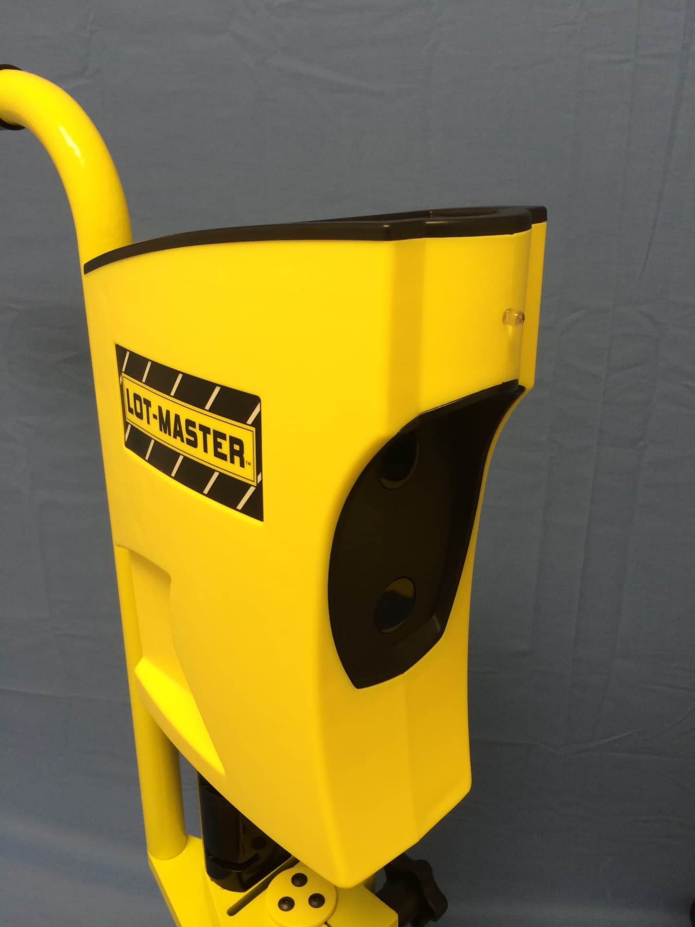
Click to zoom
Application Details
- Equipment Class
- DXX - Part 15 Low Power Communication Device Transmitter
- Date of Grant
- Aug 21, 2014
- Application Purpose
- Original Equipment
- Date of Application
- Aug 21, 2014
- Equipment Note
- INFRARED ALIGNMENT DEVICE
- Frequency Range
- 915.00000000 - 915.00000000
- Company
- Invis-a-Beam LLC
- Country
- United States
Documents & Files
Document Text
Text extracted from the exhibit documents filed with the FCC. Open a document above to read the original.
Users Manual
User Manual MODEL LM-100-AA IMPORTANT: User mus t read and understand this User Manual before use of this product. Naples, Florida USA 1-239-244-8555 www.invis-a-beam.com 2 TABLE OF CONTENTS Introduction ............................................................2 Package Contents...................................................3 Assembly ..............................................................5 Operation..............................................................11 W arnings...............................................................22 Product Care..........................................................24 Troubleshooting......................................................24 Warranty................................................................27 Product Registration................................................27 Parts and Accessories.............................................28 Customer Service...................................................28 Technical Specifications...........................................29 Disclosures...........................................................30 FCC W arnings.......................................................30 INTRODUCTION Thank you for purchasing this product from Invis-a -Beam LLC. This high quality product has been designed, built and tested to the upmost standards to perform accurately and reliably for ma ny years of satisfied use. Please read and understand the contents of this User Manual before operating this product. 3 PACKAGE CONTENTS (1) Receiving Infrared Head Unit “A” (1) Transmitting Infrared Head Unit “B” (1) RF Radio Receiver (2) Upper Stand Assemblies (2) Stand Poles (2) Stand Bases (1) Radio Receiver Lanyard with Clip (1) 9V AC Power Charger (1) Power Charger Splitter Cable (2) AA Batteries (1) W hite Dry Paint Marker (1) 3/16” Hex Key (4) Black Button Head Sc r ews 5/16”-18, 3/4”L (4) Black Split Lock Washers 9/16” OD (2) Black Flat Washers 5/16” ID, 3/4" OD (2) Stainless Steel Flat Washers 5/16” ID, 1” OD (See Figure 1 and Figure 2) 4 5 ASSEMBLY UNPACKING 1.The product’s contents c o me in two foam packaging trays. Remove the top piece of foam. Carefully remove all of the parts in the top tray before removing the top tray from the box. Next remove the e mpty top foam tray. Then carefully remove the contents of the bottom tray. 2.Inspect the contents carefully to ma ke sure that no damage or breakage had occurred during shipping. 3.Do not discard the packaging material until you have inspected the product, identified all of the parts and successfully operated the product. 4.If any parts are missing or damaged, please contact Customer Service for assistance. ASSEMBLING THE STANDS LOCATE HEX KEY AND MOUNT ING HARDWARE (See Figure 2) ATTACHING STAND POLE TO STAND BASE (See Figure 3) 1.Holding a Stand Pole fi rmly in one hand, place a Stand Base upside down on top of the Stand Pole with the recessed cup over the end of the Stand Pole, rotating it until the pin in the cup mates up with the hole at the end of the Stand Pole. 2.With the bottom of the Stand Base facing upward, place a Stainless Steel Flat Washer and a Black Split Lock Washer over the mounting hole. Install a Black Button Head Screw through the two washers and into the mounting hole. Screw the Button Head Screw into the hole using the Hex Key until snug. Do not fully tighten! 6 Fig.3 ATTACHING THE UPPER STAND ASSEMBLY TO THE STAND POLE AND STAND BASE (See Figure 4) 1.With the Stand Pole and Stand Base attached, place the Stand Base on a flat surface with the rubber bumpers down. Place an Upper Stand Assembly on the Stand Pole with the recessed cup on the bottom side over the end of the Stand Pole rotating it until the pin in the cup mates up with the hole at the end of the Stand Pole. 2. Place a Black Flat Washer and a Black Split Lock Washer over the mounting hole. Install a Black Button Head Screw through the two washers and into the mounting hole. Screw the Button Head Screw into the hole using the Hex Key until snug. Do not fully tighten! 7 Fig.4 ALIGNING THE STAND ASSEMBLY (See Figure 5) 1.Place the assembled Stand Assembly on the floor. Looking directly over the top of the Stand Assembly with the mounting screws snug and not fully tightened, rotate the handle of the Stand Assembly until the handle is aligned with the front tip of the Stand Base. 2.W ithout disturbing the alignment, fully tighten the mounting screw on the Upper Stand Assembly with the Hex Key. 3.Carefully turn the stand upside down. Fi rmly holding it in one hand, fully tighten the mounting screw at the bottom of the Stand Base. 8 4.Place the Stand Assembly on the floor to check its alignment. If not correctly aligned, loosen both mounting screws and repeat this procedure until aligned correctly. Fig.5 REPEAT PREVIOUS PROCEDURES FOR THE REMAINING STAND ASSEMBLY. ATTACHING INFRARED HEAD UNITS TO STAND ASSEMBLIES ( See Figure 6) 1.Fi rmly holding one of the Infrared Head Units, in one hand, place the base of the Head Unit on top of the do me of the Stand Assembly with the Head Unit Lenses facing away from the Stand Handle. 2.With the other hand, align the 5/8” Center Screw that is located in the center hole of the Do me of the Stand Assembly with the hole located on the bottom side of the Infrared Head Unit base. Tighten the Center Screw Knob by hand until the Infrared Head Unit is fi rmly in place. 9 3.Repeat this procedure with the remaining Infrared Head Unit and Stand Assembly. Fig.6 ASSEMBLING THE RF RADIO RECEIVER ( See Figure 7) 1.Remove the battery door located on the backside of the RF Radio Receiver. 2.Insert the 2 AA Batteries into the battery compartment, observing the positive (+) and negative (– ) markings indicated in the battery compartment. 3.Replace battery door. 10 4.Attach the Lanyard to the RF Radio Receiver by clipping the Lanyard to the ring on the top of the Radio. 11 OPERATION CHARGING THE INFRARED HEAD UNITS Charge the Infrared Head Units for 14…
Text truncated - open the document above for the full version.
External Photos
APPLICANT: INVIS-A-BEAM LLC FCC ID: 2ABHS00100AA EXTERNAL PHOTOS
ID Label/Location Info
FCC LABELS Label for Lot-Master Handheld Radio and IR Sender “B”: Label for Line-Wizard Handheld Radio and IR Sender “B”: Label for Lot-Master and Line-Wizard IR Receiver/RF Transmitter: *****Labels are also shown in attached pictures.
Internal Photos
APPLICANT: INVIS-A-BEAM LLC FCC ID: 2ABHS00100AA INTERNAL PHOTOS
Test Report
FCC PART 15.249 TEST REPORT UNLICENSED INTENTIONAL RADIATOR Applicant INVIS-A-BEAM LLC Address 2021 TIMBERLINE DR NAPLES FL 34109-7126 USA FCC ID 2ABHS00100AA Model Number LM -100-AA and LW-100-AA Product Description LOT-MASTER FCC Standard Applied 47 CFR §15.249 Date Sample Received 8/18/2014 Date Tested 8/19/2014 Tested By S. S. SANDERS Approved By Cory Leverett Report Number 1293AZUT14TestReport.docx Test Results PASS FAIL THE ATTACHED REPORT SHALL NOT BE REPRODUCED EXCEPT IN FULL WITHOUT THE WRITTEN APPROVAL OF TIMCO ENGINEERING, INC. 849 NW State Road 45 Newberry, FL 32669 USA Ph: 888.472.2424 or 352.472.5500 Fax: 352.472.2030 Email: [email protected] Website: www.timcoengr.com APPLICANT: INVIS-A-BEAM LLC FCC ID: 2ABHS00100AA REPORT: I\INVIS\1293AZUT14\1293AZUT14TestReport.docx Page 7 of 21 TABLE OF CONTENTS GENERAL REMARKS .................................................................................................................. 2 GENERAL INFORMATION ........................................................................................................... 3 TEST RESULTS SUMMARY ......................................................................................................... 3 TEST PROCEDURES ................................................................................................................... 4 RADIATION INTERFERENCE ...................................................................................................... 5 Test Setup: ............................................................................................................................... 5 RADIATION INTERFERENCE ...................................................................................................... 6 Test Setup: ............................................................................................................................... 6 Radtstsetup2 ............................................................................................................................. 6 RADIATION INTERFERENCE FUNDAMENTAL HORIZONTAL ...................................................... 7 RADIATION INTERFERENCE FUNDAMENTAL VERTICAL ........................................................... 8 RADIATION INTERFERENCE 30- 200MHZ HORIZONTAL ......................................................... 9 RADIATION INTERFERENCE 30 200 MHZ VERTICAL ............................................................. 10 RADIATION INTERFERENCE 200 1000 MHZ HORIZONTAL ................................................... 11 RADIATION INTERFERENCE 200 1000 MHZ VERTICAL ........................................................ 12 RADIATION INTERFERENCE 1 10GHZ HORIZONTAL ............................................................. 13 RADIATION INTERFERENCE 1 10GHZ VERTICAL ................................................................... 14 OCCUPIED BANDWIDTH & BANDEDGE: .................................................................................. 15 OCCUPIED BANDWIDTH & BANDEDGE .................................................................................... 16 POWER LINE CONDUCTED INTERFERENCE ............................................................................. 17 POWERLINE CONDUCTED EMISSIONS TEST SET UP PHOTO ................................................... 18 POWER LINE CONDUCTED INTERFERENCE PLOT LINE 1 ......................................................... 19 POWER LINE CONDUCTED INTERFERENCE PLOT LINE 2 ......................................................... 20 EMC EQUIPMENT LIST ............................................................................................................. 21 APPLICANT: INVIS-A-BEAM LLC FCC ID: 2ABHS00100AA REPORT: I\INVIS\1293AZUT14\1293AZUT14TestReport.docx Page 2 of 21 GENERAL REMARKS The attached report shall not be reproduced except in full without the written permission of Timco Engineering Inc. Summary The device under test does: fulfill the general approval requirements as identified in this test report not fulfill the general approval requirements as identified in this test report Attestations This equipment has been tested in accordance with the standards identified in this test report. To the best of my knowledge and belief, these tests were performed using the measurement procedures described in this report. All instrumentation and accessories used to test products for compliance to the indicated standards are calibrated regularly in accordance with ISO 17025: 2005 requirements. I attest that the necessary measurements were made, under my supervision, at: Timco Engineering Inc. 849 NW State Road 45 Newberry, Fl 32669 Authorized Signatory Name: Project Manager: Sid Sanders Date: 8/19/2014 TABLE OF CONTENTS APPLICANT: INVIS-A-BEAM LLC FCC ID: 2ABHS00100AA REPORT: I\INVIS\1293AZUT14\1293AZUT14TestReport.docx Page 3 of 21 GENERAL INFORMATION EUT Specification The test results relate only to the items tested. Applicable Standard Part 15.249 EUT Description LOT-MASTER FCC ID 2ABHS00100AA Model Number LM -100-AA and LW-100-AA Operating Frequency TX: 915 MHz RX: Same No. of Channels Modulations EUT Power Source 110–120Vac/50– 60Hz DC Power Battery Operated Exclusively Test Item Prototype Pre- Production Production Type of Equipment Fixed Mobile Portable Antenna Connector FCC Rules require that the antenna connector be unique. Test Facility Timco Engineering Inc. located at 849 NW State Road 45 Newberry, FL 32669 USA. Conditions in the Test laboratory Temperature: 26ºC Relative humidity: 50% Test Exercise The EUT was placed in continuous transmit mode of operation. Revision History of EUT New Test Supporting Equipment Supporting Device Manufacturer Model / FCC ID Serial Number N/A TEST RESULTS SUMMARY Specification – Rules Part No. RESULTS – Pass/Fail/NA FCC Rule 15.249 Fundamental PASS FCC Rule 15.249 Harmonics & Spurious PASS Bandedge PASS Power Line Emissions 15.207 PASS TABLE OF CONTENTS APPLICANT: INVIS-A-BEAM LLC FCC ID: 2ABHS…
Text truncated - open the document above for the full version.
Test Setup Photos
APPLICANT: INVIS-A-BEAM LLC FCC ID: 2ABHS00100AA TEST SET UP PHOTOS RADIATED EMISSIONS TEST SET UP PHOTOS POWERLINE CONDUCTED EMISSIONS TEST SET UP
Contact Information
Applicant
Paul J Weiner(CEO)
Technical Contact
Timco Engineering, Inc.Sid Sanders
[email protected]888-472-2424
849 NW State Road 45 · Newberry · United States
Non-Technical Contact
Timco Engineering, Inc.Sharon Hoffman
[email protected]888-472-2424
Test Firm
Timco Engineering, Inc.Bruno Clavier
Technical Specifications
| # | Rule Parts | Frequency Range | Power Output |
|---|---|---|---|
| 1 | 15C | 915 MHz - 915 MHz | - |
Other Applications from Invis-a-Beam LLC
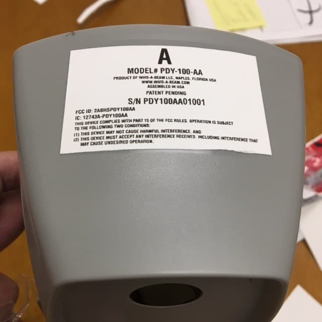
2ABHSPDY100AA
Dec 13, 2015RF Transmitter Head Unit A
Equipment Class
DXX - Part 15 Low Power Communication Device Transmitter