2ABHSPDY100AARF Transmitter Head Unit A
Invis-a-Beam LLC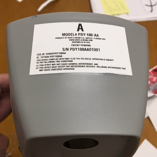
Click to zoom
Application Details
- Equipment Class
- DXX - Part 15 Low Power Communication Device Transmitter
- Date of Grant
- Dec 13, 2015
- Application Purpose
- Original Equipment
- Date of Application
- Dec 13, 2015
- Equipment Note
- RF Transmitter Head Unit A
- Frequency Range
- 916.25000000 - 917.75000000
- Company
- Invis-a-Beam LLC
- Country
- United States
Documents & Files
Document Text
Text extracted from the exhibit documents filed with the FCC. Open a document above to read the original.
Users Manual
User Manual MODEL PDY-100-AA IMPORTANT: USER MUST READ AND UNDERSTAND THIS USER MANUAL BEFORE USE OF THIS PRODUCT. Naples, Florida USA 1-239-244-8885 www.invis-a-beam.com TABLE OF CONTENTS Introduction.................................................................2 Package Contents........................................................3 Unpacking...................................................................3 Installing Infrared Head Units..........................................4 Installing RF Radio Receivers........................................10 Operation...................................................................12 Alternative Uses..........................................................13 Programming Alternative Channels.................................14 Restoring Factory Channel Settings................................14 Warnings...................................................................15 Product Care..............................................................16 Troubleshooting..........................................................17 Warranty....................................................................18 Disclosures................................................................18 Product Registration.....................................................18 Parts and Accessories..................................................19 Customer Service........................................................19 Technical Specifications.................................................19 FCC & IC Warnings......................................................20 INTRODUCTION Thank you for purchasing this product from Invis-a-Beam LLC. This high quality product has been designed, built and tested to the utmost standards to perform accurately and reliably for many years of satisfied use. Please read and understand the contents of this User Manual before operating this product. 2 PACKAGE CONTENTS (1) Receiving Infrared Head Unit “A” (1) Transmitting Infrared Head Unit “B” (2) RF Radio Receivers (4) 1” #8 Pan Head Screws (4) Screw Anchors (See Figure 1 and Figure 2) UNPACKING 1. The product contents are set in a cardboard tray. Carefully remove all of the parts in the tray. 2. Inspect the contents carefully to make sure that no damage or breakage has occurred. 3. Do not discard the packaging material until you have inspected the product, identify all of the parts and successfully operated the product. 3 4. If any parts are missing or damaged, please contact Customer Service for assistance. INSTALLING INFRARED HEAD UNITS There are 2 Infrared Head Units with this system, “A” and “B”. Infrared Head Unit “A” is marked with the letter “A” on the bottom label and also has a small Channel Programming Hole to the left of the LED on the top of the head unit. Infrared Head Unit “B” is marked with the letter “B” on the bottom label and has only a LED on the top of the head unit. It does not matter which Infrared Head Unit is mounted to each mounting wall. (See Figure 1) The Park-Daddy™ Vehicle Parking System is designed to be mounted in the garage to notify the operator of a vehicle when the rear bumper has cleared the garage door opening and it will be safe to close the garage door, leaving the maximum amount of room in the front of the vehicle. The Park-Daddy™ Vehicle Parking System can be used in garages with up to 4 parking spots across. The Park-Daddy™ can also be used as an invisible barrier in the front and the side of the vehicle to warn you when a vehicle is close to objects placed in the garage. For installation instructions for the other alternative uses, please refer to the Alternative Uses section. INSTALLING BATTERIES. Each Infrared Head Unit requires (2) D size alkaline batteries to be installed. (Batteries not included.) 1. Remove battery door by pulling down the tab on top of the battery door and pulling the top of the door outward. 2. Hold the Infrared Head Unit in one hand with the opening upward and the top of the Head Unit facing away (The top of the Head Unit has the product label and the LED). 3. Install the first battery with the (+) positive terminal touching the contact in the top end on the battery compartment. 4. While holding the first battery in place with your thumb, place the (-) negative terminal of the second battery on the spring in the lower 4 YOU CAN ALSO SEE THE FOLLOWING INSTALLATION AND OPERATION INSTRUCTIONS IN THE PARK-DADDY™ PAGE AT: WWW.PARK-DADDY.COM section of the battery compartment and compress the spring until there is enough clearance for the second battery’s (+) positive terminal to make contact with the first battery’s (-) negative terminal. 5. Replace the battery door with the tab on the bottom of the door inside the battery compartment first then pull down the locking tab on the top of the door and push the battery door inward until the door completely closes. 6. Repeat the above procedure on the remaining Infrared Head Unit. The Red LED on Infrared Head Unit “A” will illuminate and the LED on Infrared Head Unit “B” will flash Green every 15 seconds after batteries are installed until both Infrared Head Units are paired. DETERMINING VEHICLE CLEARENCE. Locate Mounting Template at the end of this User Manual. The distance from the inner part of the garage door and line “B” of the Mounting Template can be determined by the following: 1. With the garage door in the closed position, determine the inner most point of the interior section of the garage door including handles, hinges, supports, hurricane struts or trusses and any other protrusion attached to the interior of the door. 2. Using a pencil, erasable marker or a piece of tape, mark the floor of the garage at each end of the garage door twice approximately 6 inches apart at the inner most point of the interior section of the garage door. Run a straight edge from both marks to the mounting walls and place a mark on the bottom of each mounting wall. 3. By marking …
Text truncated - open the document above for the full version.
Block Diagram
PUSHBUTTON CONFIG SWITCH RED GREEN BI-COLOR LED PROGRAMMING INTERFACE +3.3 VDC POWER SUPPLY +3V3 MICROCONTROLLER 8-BIT W/INTERNAL 16 MHZ OSCILLATOR IR DETECTOR IR DETECTOR PCB ANTENNA Si-4455 BASED RF SECTION 8 MHZ CLOCK TX ONLY (2) "D" SIZE ALKALINE 3 VOLT BOOST SWITCHING DETECTION WAKEUP PARK-DADDY IR HEAD UNIT A W/RF TRANSMITTER INVIS-A-BEAM LLC B. English 12-06-2015
External Photos
APPLICANT: INVIS-A-BEAM LLC FCC ID: 2ABHSPDY100AA IC: 12743A-PDY100AA EXTERNAL PHOTOS
Internal Photos
APPLICANT: INVIS-A-BEAM LLC FCC ID: 2ABHSPDY100AA IC: 12743A-PDY100AA INTERNAL PHOTOS
Operational Description
4707 Enterprise Ave., Suite #2, Naples, Florida, 34104 Main - 239-244-8885 Fax – 239-244-8881 Email - [email protected] PARK-DADDY Circuit Description December 7, 2014 B. English The Invis-a-Beam LLC PARK-DADDY system is designed to align objects in a straight line up to 30 meters using infrared technology. Feedback on the status of the alignment is transmitted via RF to a 12-Volt automotive cigarette lighter socket powered RF receiver. Each system consists of three components. The following are descriptions of each of these components. 1. Transmitting Infrared Head Unit “B”: The Transmitting Infrared Head Unit contains a single printed circuit assembly. It is powered by (2) “D” size alkaline batteries. The circuit board contains a microcontroller to generate infrared pulses via two 940 nm infrared emitting diodes. It also provides battery monitoring and status via a bi-color red/green LED. 2. Receiving Infrared Head Unit “A”: The Receiving Infrared Head Unit contains a single printed circuit assembly. It is powered by (2) “D” size alkaline batteries. The circuit board contains a microcontroller to receive infrared pulses via two 940 nm infrared receiver modules. It also provides battery monitoring and status via a bi-color red/green LED. The board utilizes a Silicon Labs Si4455 based RF transmitter with a printed circuit antenna. When the infrared beam is broken, the microcontroller will begin transmitting via the Si4455 to the RF Radio Receiver. A tactile pushbutton switch is implemented to allow channel changing from 916.25 to 917.75 MHz in 250 KHz steps. When transmissions are active, they occur continuously every 50 mS with a 5mS duration. 3. RF Radio Receiver Unit: The Radio Receiver Unit contains a single printed circuit assembly. The circuit board contains a microcontroller, Silicon Labs Si4455 based RF receiver, audible tone generator, tactile switches for tone volume control and LED indicators. The unit contains a speaker for the tone generation and is powered through a 12-Volt automotive cigarette lighter plug. The device is operated as an RF receiver only; utilizing a printed circuit board antenna. When powered up, the microcontroller monitors the RF receiver for valid packet receptions. Upon reception of a valid code, the unit will illuminate red LEDs and if so enabled, sound a tone indicating that the IR beam has been broken between the Transmitting Infrared Head Unit and Receiving Infrared Head Unit. When the IR beam is re-established, the RF transmissions will stop and the tone disabled. In this state the LEDs will illuminate green.
Schematics
1 1 2 2 3 3 4 4 5 5 6 6 DD CC BB AA Title NumberRevisionSize B Date:12/7/2015Sheet of File:C:\Users\..\PDY-200_Sheet2.SchDocDrawn By: GND 1 SDN 2 RXp 3 RXn 4 TX 5 GND 6 VDD 7 VDD 8 GND 9 GPIO0 10 GPIO1 11 nIRQ 12 SCLK 13 SDO 14 SDI 15 nSEL 16 XOUT 17 XIN 18 GPIO2 19 GPIO3 20 EP EP U1 Si4455-C2A-GM 12 6n8 L2 12 6n8 L3 12 8n2 L5 12 22n L7 1 2 18n L6 1 2 100n L4 1 2 100n C10 1 2 100p C12 1 2 2u2 C13 +3V3 1 2 33p C11 RF_MOSI RF_nSEL RF_SDN RF_SCLK RF_MISO ANT1 PCB Antenna 1 2 5p1 C3 1 2 10p C5 1 2 5p1 C7 1 2 3p C9 +3V3 12 1p2 C8 12 33pF C6 12 56p C4 1 2 2p7 NU C2 12 0R L1 1 2 1p5 C1 (NU for Stick)(2p7 for Stick) (33n for Stick) 13 24 Y1 TZ1430A 30 MHz PARK-DADDY IR RX A 22 ENGLISH PDY-200
Test Report
FCC PART 15.249 & IC RSS-210 UNLICENSED INTENTIONAL RADIATOR TEST REPORT Applicant INVIS-A-BEAM LLC Address 4707 ENTERPRISE AVE UNIT #2 NAPLES FL 34104 USA FCC ID 2ABHSPDY100AA IC Certification Number 12743A-PDY100AA Model Number PDY-100-AA Product Description RF TRANSMITTER HEAD UNIT A Date Sample Received 8/27/2015 Final Test Date 9/8/2015 Tested By Cory Leverett Approved By Sid Sanders Report Number Version Number Description Issue Date 1789UT15TestReport Rev1 Initial Issue 9/9/2015 THE ATTACHED REPORT SHALL NOT BE REPRODUCED EXCEPT IN FULL WITHOUT THE WRITTEN APPROVAL OF TIMCO ENGINEERING, INC. 849 NW State Road 45 Newberry, FL 32669 USA Ph.: 888.472.2424 or 352.472.5500 Fax: 352.472.2030 Email: [email protected] Website: www.timcoengr.com APPLICANT: INVIS-A-BEAM LLC FCC ID: 2ABHSPDY100AA IC: 12743A-PDY100AA REPORT: I\INVIS\1789IC15\1789IC15TestReport.docx Page 2 of 17 Table of Contents GENERAL REMARKS ................................................................................ 3 GENERAL INFORMATION .......................................................................... 4 TEST RESULTS SUMMARY ........................................................................ 5 OCCUPIED BANDWIDTH ........................................................................... 6 BAND-EDGE ......................................................................................... 10 DUTY CYCLE ......................................................................................... 12 RADIATION INTERFERENCE .................................................................... 14 EMC EQUIPMENT LIST ........................................................................... 17 APPLICANT: INVIS-A-BEAM LLC FCC ID: 2ABHSPDY100AA IC: 12743A-PDY100AA REPORT: I\INVIS\1789IC15\1789IC15TestReport.docx Page 3 of 17 GENERAL REMARKS The attached report shall not be reproduced except in full without the written permission of Timco Engineering Inc. Summary The device under test does: Fulfill the general approval requirements as identified in this test report Not fulfill the general approval requirements as identified in this test report Attestations This equipment has been tested in accordance with the standards identified in this test report. To the best of my knowledge and belief, these tests were performed using the measurement procedures described in this report. All instrumentation and accessories used to test products for compliance to the indicated standards are calibrated regularly in accordance with ISO 17025: 2005 requirements. I attest that the necessary measurements were made, under my supervision, at: Timco Engineering Inc. 849 NW State Road 45 Newberry, FL 32669 Authorized Signatory Name: Cory Leverett Project Manager Date: 9/9/2015 Table of Contents APPLICANT: INVIS-A-BEAM LLC FCC ID: 2ABHSPDY100AA IC: 12743A-PDY100AA REPORT: I\INVIS\1789IC15\1789IC15TestReport.docx Page 4 of 17 GENERAL INFORMATION EUT Specification FCC Regulatory Standard Title 47 CFR Part 2 & 15 IC Regulatory Standard RSS-210 (i8) & RSS-GEN (i4) FCC ID 2ABHSPDY100AA IC 12743A-PDY100AA Model PDY-100-AA EUT Description RF TRANSMITTER HEAD UNIT A Operating Frequency TX: 916.25-917.75 MHz RX:NA EUT Power Source 110–120Vac/50– 60Hz DC Power Battery Operated Exclusively Test Item Prototype Pre- Production Production Type of Equipment Fixed Mobile Portable Antenna Connector None Antenna Integrated PCB Trace Antenna Test Facility Timco Engineering Inc. located at 849 NW State Road 45 Newberry, FL 32669 USA. Test Conditions Temperature: 24-26ºC Relative humidity: 50-65% Measurement Standards IC RSS-GEN Issue 4 FCC CFR 47 Part 15.31 ANSI C63.10-2013 (test methods) ANSI C63.4-2009 (Site Validation) Test Exercise Transmitting under Normal Modulation Test Supporting Equipment Device Manufacturer Model S/N Supplied By Use NA APPLICANT: INVIS-A-BEAM LLC FCC ID: 2ABHSPDY100AA IC: 12743A-PDY100AA REPORT: I\INVIS\1789IC15\1789IC15TestReport.docx Page 5 of 17 TEST RESULTS SUMMARY Requirement FCC Rule Part IC RSS Result Fundamental & Harmonic Emissions 15.249 (a)(c)(e) 210 § A2.9 Pass Occupied Bandwidth 15.215 (c) GEN § 6.6 Pass Bandedge Compliance 15.249 (c)(d)(e) 15.209 210 § A2.9(b) GEN § 8.9 Pass Spurious Emissions 15.249 (c)(d)(e) 15.209 210 § A2.9(b) GEN § 8.9 Pass AC Power Line Conducted Emissions 15.207 GEN § 8.8 NA(1) Restricted Band Emissions 15.205 210 § 2.2 GEN § 8.10 Pass Antenna Requirements 15.203 GEN § 8.3 Pass Notes: 1. This EUT is battery powered only, no provision is provided to connect to the public AC mains utility Table of Contents APPLICANT: INVIS-A-BEAM LLC FCC ID: 2ABHSPDY100AA IC: 12743A-PDY100AA REPORT: I\INVIS\1789IC15\1789IC15TestReport.docx Page 6 of 17 OCCUPIED BANDWIDTH Rules Part No.: FCC 15.215(c) & IC RSS-GEN § 6.6 Requirements: FCC requires that the 20 dB bandwidth of the emission shall be contained within the frequency band designated under which the equipment is operated. Industry Canada 99% Bandwidth reporting only Method of Measurement: ANSI C63.10 § 6.9 Occupied bandwidth tests Test Data: Low End of Band 20 dB OCC BW = 89.74 KHz RESULTS MEET REQUIREMENTS Table of Contents APPLICANT: INVIS-A-BEAM LLC FCC ID: 2ABHSPDY100AA IC: 12743A-PDY100AA REPORT: I\INVIS\1789IC15\1789IC15TestReport.docx Page 7 of 17 OCCUPIED BANDWIDTH Test Data: High End of Band 20 dB OCC BW = 89.74 KHz RESULTS MEET REQUIREMENTS Table of Contents APPLICANT: INVIS-A-BEAM LLC FCC ID: 2ABHSPDY100AA IC: 12743A-PDY100AA REPORT: I\INVIS\1789IC15\1789IC15TestReport.docx Page 8 of 17 OCCUPIED BANDWIDTH Test Data: Low End of Band 99% OCC BW = 111.37 KHz RESULTS MEET REQUIREMENTS Table of Contents APPLICANT: INVIS-A-BEAM LLC FCC ID: 2ABHSPDY100AA IC: 12743A-PDY100AA REPORT: I\INVIS\1789IC15\1789IC15TestReport.docx Page 9 of 17 OCCUPIED BANDWIDTH Test Data: High End of Band 99% OCC BW = 112.17 KHz RESULTS MEET REQUIREMENTS Table of Contents APPLICANT: INVIS-A-BEAM LLC FCC ID: 2ABHSPDY100AA IC: 12743A-PDY100AA REPORT: I\INVIS\1789IC15\1789IC15TestRepo…
Text truncated - open the document above for the full version.
Test Setup Photos
APPLICANT: INVIS-A-BEAM LLC FCC ID: PDY100AA TEST SET UP PHOTOS RADIATION INTERFERENCE BELOW 30 MHz RADIATION INTERFERENCE Below 1 GHz RADIATION INTERFERENCE Above 1 GHz 20 DB BANDWIDTH 99% DB BANDWIDTH BANDEDGE DUTY CYCLE
Contact Information
Applicant
Paul J Weiner(CEO)
Technical Contact
Timco Engineering, Inc.Cory Leverett
[email protected]8884272424
849 NW State Road 45 · NEWBERRY, Florida · United States
Non-Technical Contact
Timco Engineering, Inc.Sharon Hoffman
[email protected]8884272424
Test Firm
Timco Engineering, Inc.Bruno Clavier
Technical Specifications
| # | Rule Parts | Frequency Range | Power Output |
|---|---|---|---|
| 1 | 15C | 916.25 MHz - 917.75 MHz | - |
Other Applications from Invis-a-Beam LLC

2ABHS00100AA
Aug 21, 2014INFRARED ALIGNMENT DEVICE
Equipment Class
DXX - Part 15 Low Power Communication Device Transmitter