2ABHWBN-HH-G02Smart terminal
BayNexus Inc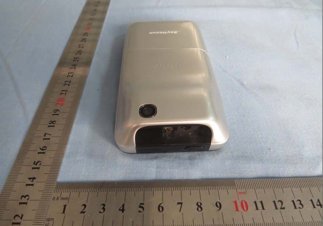
Click to zoom
Application Details
- Equipment Class
- DSS - Part 15 Spread Spectrum Transmitter
- Date of Grant
- Mar 04, 2014
- Application Purpose
- Original Equipment
- Date of Application
- Feb 27, 2014
- Equipment Note
- Smart terminal
- Frequency Range
- 902.25000000 - 927.75000000
- Company
- BayNexus Inc
- Country
- China
Documents & Files
Document Text
Text extracted from the exhibit documents filed with the FCC. Open a document above to read the original.
Users Manual
BayNexus Inc I BN-HH-G02 User Manual FCC ID:2ABHWBN-HH-G02 Table of Content 1. Device Description ............................................................................... 1 2. Parameters .......................................................................................... 2 3. Device installation ............................................................................... 3 3.1. Unpack ....................................................................................... 3 3.2. Rear Cover Open or Close .......................................................... 3 3.3. Install a Memory SD Card ........................................................... 3 3.4. Install a Battery .......................................................................... 4 3.5. Charging Notice .......................................................................... 5 4. BN_DEMO Operation Guide ................................................................ 5 4.1. BN_DEMO_UHF (900MHz) ......................................................... 5 5. RFID Notice .......................................................................................... 7 FCC Regulations: ....................................................................................... 8 BayNexus Inc 1 1. Device Description Barcode Main screen Volume Left scan Power Right Scan Camera RFID 2 2. Parameters Common parameters CPU 1.2GHz dual-core Operating system Android 4.0 Inner module RFID Reader, Barcode Reader Dimension 137*68*20(28)mm Weight 245g (with battery) Camera 5M pixel,automatic focusing GPS positioning Yes Display screen Type TFT capacitance multi touch screen Dimension 800*480 pixel,4.3 inch screen Volume Ring Various rings and vibration Inner speaker Yes Inner microphone Yes Memory Memory expansion Micro SD,maximum 32G Internal memory RAM 512MB UHF ISO 18000-6C,EPC Gen2 Barcode reader Reader type CCD Image Reader Barcode type One dimensional barcode and all typological two dimensional barcode e.g.: PDF417,Datamatrix,Maxicode,Code 16k, Code 49,QR code,Code one etc. Battery Type 3.7V,Li-Ion 1800(2800) mAh battery Stand-by time* Maximum 48 hours Work time** Maximum 8 hours SDK Operating system Android 4.0 Language Java(JDK 16) Development Environment Java SE Development Kit Eclipse,Android SDK r18 ADT Plugin for Eclipse *Standby condition: screen off, barcode and RFID off **Operation condition: screen on, barcode and RFID on 3 3. Device installation 3.1. Unpack Check your product box for the following items: handheld device Battery(two) Travel charger User manual Product quality card 3.2. Rear Cover Open or Close ① Poking at the back cover along the direction of the arrow ② Then directly remove the back cover 3.3. Install a Memory SD Card ① Push the cover along the direction of the 4 arrow. ② Insert the memory card into the slot according the picture. ③ Lock the cover along the direction of the arrow. 3.4. Install a Battery ① Embed the battery along the direction of the arrow. ② Press the battery. 4. 3.5. C Please cha ***Only u BN_DE 4.1. B Graph 1:M Graph 2:S Charging arge the batt use the prov EMO O BN_DEM Menu Selectio ingle RFID Re g Notice tery full befo ided charge Operatio MO_UHF on ead Screen ③ Close direct fore the first er for battery on Gui F (900M e the cove tion of the t-time use. y charging p de Hz) er and cla arrow. purpose!*** mp along * 5 the Graph 3:M Graph 4: B To enter B BN-HH-G the icon. U are threebu User en “RFID_Sin Multiple RFID Barcode Scann BN_DEMO_ G02’s Andro User will be uttons for us nters sing ngle_Read( Read Screen ning Screen _UHF appl oid Home Sc e presented ser to choos gle RFID (EPC)”or“R lication, loc creen or Ap d with the in se which mo D read RFID_Single cate the BN pplication S nterface sho ode to enter mode b e_Read(TID N_DEMO_U Screen, then own in [Gr r. by single D)” button UHFicon on n single-clic raph 1]. T -clicking n. The si 6 n the k on There the ingle 7 RFID read mode interface is shown in [Graph 2].When in this mode, user can single-click “Read” button or press the physical ‘scan’ button on the right side of the BN-HH-G02 to start the single RFID read operation. The single RFID read operation ends with either a successful read of a single RFID or a time-out event. User enters multiple RFID read mode by single-clicking “RFID_Multi_Read(EPC)” or “RFID_Multi_Read(TID)”button in [Graph 1]. The multiple RFID read mode interface is shown in [Graph 3]. When in this mode, user can single-click the “Read” button or press the physical “scan” button to start the multiple RFID read operation. User stops the multiple RFID read operation by single-clicking the “Stop” button. Please make sure to stop the “RFID_Multi_Read” function when not using this function; otherwise, the battery power will drain fast! User enters bar code scanning mode by single-clicking the “BarCode” button in [Graph 1]. The barcode scanning mode interface is shown in [Graph 4]. User can single-click the “Read” button or press the physical “scan” button on the left side of the BN-HH-G02 to start the barcode scanning operation. The barcode scanning operation ends with a successful read of a barcode or a time-out event. 5. RFID Notice When you use the RFID function, do not cover the RFID antenna area on the rear of the device. Suggest to holdboth sides of the device, and to read the tag as shown below. 8 FCC Regulations: This device complies with part 15 of the FCC Rules. Operation is subject to the following two conditions: (1) This device may not cause harmful interference, and (2) this device must accept any interference received, including interference that may cause undesired operation. NOTE: This equipment has been tested and found to comply with the limits for a Class B digital device, pursuant to part 15 of the FCC Rules. These limits are designed to provide reasonable protection against harmful interference in a residential installation. This equipment generates, uses and can radia…
Text truncated - open the document above for the full version.
Cover Letter(s)
BayNexus Inc Add: B307,530 Building TaiHu International Science park, Wuxi, China TEL: 086-510-85387912-815 FAX: 086-510-85387912-803 January 23, 2014 POWER OF ATTORNEY To Whom It May Concern: We, the undersigned, hereby authorize TA Technology (Shanghai) Co., Ltd. on our behalf, to apply to (R&TTE Directive)99/5/EEC on our equipment. Any and all acts carried out by TA Technology (Shanghai) Co., Ltd. on our behalf shall have the same effect as acts of our own. Sincerely, BayNexus Inc <SIGNATURE> ------------------------------- (Jason Liu) (General Manager)
External Photos
2ABHWBN-HH-G02 External Photo
ID Label/Location Info
2ABHWBN‐HH‐G02 Label and Label Location
Internal Photos
2ABHWBN-HH-G02 Internal photo Antenna
RF Exposure Info
Report No. RXA1310-0177SAR Page 1 of 64 TESTING No. L2264 SAR TEST REPORT Product Name Smart terminal Model Name BN-HH-G02 Brand Name Baynexus FCC ID 2ABHWBN-HH-G02 Client BayNexus Inc Manufacturer GUANGDONG SIMDO TECHNOLOGY Co.,LTD. Date of issue January 13, 2014 TA Technology (Shanghai) Co., Ltd. TA Technology (Shanghai) Co., Ltd. Test Report Report No. RXA1310-0177SAR Page 2 of 64 GENERAL SUMMARY Reference Standard(s) FCC 47CFR §2.1093 Radiofrequency Radiation Exposure Evaluation: Portable Devices ANSI C95.1, 1992: Safety Levels with Respect to Human Exposure to Radio Frequency Electromagnetic Fields, 3 kHz to 300 GHz.(IEEE Std C95.1-1991) IEEE Std 1528™-2003: IEEE Recommended Practice for Determining the Peak Spatial-Average Specific Absorption Rate (SAR) in the Human Head from Wireless Communications Devices: Measurement Techniques. KDB 865664 D01 SAR measurement 100 MHz to 6 GHz v01r02: SAR Measurement Requirements for 100 MHz to 6 GHz KDB 447498 D01 General RF Exposure Guidance v05r01: Mobile and Portable Device RF Exposure Procedures and Equipment Authorization Policies KDB 941225 D07 UMPC Mini Tablet v01r01 SAR Evaluation Procedures for UMPC Mini-Tablet Devices Conclusion This portable wireless equipment has been measured in all cases requested by the relevant standards. Test results in Chapter 7 of this test report are below limits specified in the relevant standards for the tested bands only. General Judgment: Pass Comment The test result only responds to the measured sample. Approved by Weizhong Yang Director Revised by Minbao Ling SAR Manager Performed by Yi Zhang SAR Engineer TA Technology (Shanghai) Co., Ltd. Test Report Report No. RXA1310-0177SAR Page 3 of 64 TABLE OF CONTENT 1. General Information ........................................................................................................................ 5 1.1. Notes of the Test Report .......................................................................................................... 5 1.2. Testing Laboratory ................................................................................................................... 5 1.3. Applicant Information ............................................................................................................... 6 1.4. Manufacturer Information ......................................................................................................... 6 1.5. Information of EUT ................................................................................................................... 7 1.6. The Maximum Reported SAR 1g ............................................................................................... 8 1.7. Test Date ................................................................................................................................. 8 2. SAR Measurements System Configuration ..................................................................................... 9 2.1. SAR Measurement Set-up ....................................................................................................... 9 2.2. DASY5 E-field Probe System ................................................................................................ 10 2.2.1. EX3DV4 Probe Specification .......................................................................................... 10 2.2.2. E-field Probe Calibration .................................................................................................. 11 2.3. Other Test Equipment ............................................................................................................ 11 2.3.1. Device Holder for Transmitters ........................................................................................ 11 2.3.2. Phantom ......................................................................................................................... 12 2.4. Scanning Procedure .............................................................................................................. 12 2.5. Data Storage and Evaluation ................................................................................................. 14 2.5.1. Data Storage ................................................................................................................... 14 2.5.2. Data Evaluation by SEMCAD ......................................................................................... 14 3. Laboratory Environment ................................................................................................................ 16 4. Tissue-equivalent Liquid ............................................................................................................... 17 4.1. Tissue-equivalent Liquid Ingredients ...................................................................................... 17 4.2. Tissue-equivalent Liquid Properties ....................................................................................... 18 5. System Check ............................................................................................................................... 19 5.1. Description of System Check ................................................................................................. 19 5.2. System Check Results ........................................................................................................... 20 6. Operational Conditions during Test ............................................................................................... 21 6.1. RFID Test Configuration ......................................................................................................... 21 6.2. Measurement Variability ......................................................................................................... 21 6.3. Test Positions ......................................................................................................................... 22 6.3.1. Test Positions Req…
Text truncated - open the document above for the full version.
Test Report
Report No.: RXA1310-0177RF01R1 Page 1of 50 TESTING No. L2264 Part 15C TEST REPORT Product Name Smart terminal Model BN-HH-G02 Brand Name Baynexus FCC ID 2ABHWBN-HH-G02 Client BayNexus Inc Manufacturer GUANGDONG SIMDO TECHNOLOGY Co.,LTD. Date of issue February 21, 2014 TA Technology (Shanghai) Co., Ltd. TA Technology (Shanghai) Co., Ltd. Test Report Report No.: RXA1310-0177RF01R1 Page 2of 50 GENERAL SUMMARY Reference Standard(s) FCC CFR47 Part 15C (2012) Radio Frequency Devices 15.205 Restricted bands of operation; 15.207 Conducted limits; 15.209 Radiated emission limits; general requirements; 15.247 Operation within the bands 902-928 MHz,2400-2483.5 MHz, and 5725-5850MHz. ANSI C63.4 Methods of Measurement of Radio-Noise Emission from Low-Voltage Electrical and Electronic Equipment in the Range of 9 KHz to 40GHz. (2009) DA00-705 Filing and Frequency Measurement Guidelines For Frequency Hopping Spread Spectrum System.(2000) Conclusion This portable wireless equipment has been measured in all cases requested by the relevant standards. Test results in Chapter 2 of this test report are below limits specified in the relevant standards. General Judgment: Pass Comment The test result only responds to the measured sample. Approved by Director Revised by RF Manager Performed by RF Engineer TA Technology (Shanghai) Co., Ltd. Test Report Report No.: RXA1310-0177RF01R1 Page 3of 50 TABLE OF CONTENT 1. General Information ..................................................................................................................... 4 1.1. Notes of the test report......................................................................................................... 4 1.2. Testing laboratory ................................................................................................................ 5 1.3. Applicant Information ...........................................................................................................5 1.4. Manufacturer Information ..................................................................................................... 5 1.5. Information of EUT ............................................................................................................... 6 1.6. Test Date ............................................................................................................................. 7 2. Test Information ........................................................................................................................... 8 2.1. Information about the FHSS characteristics......................................................................... 8 2.1.1. Pseudorandom Frequency Hopping Sequence...................................................................8 2.1.2. Equal Hopping Frequency Use ............................................................................................9 2.1.3. System Receiver Input Bandwidth .......................................................................................9 2.2. Test Mode ............................................................................................................................ 9 2.3. Summary of test results ....................................................................................................... 9 2.4. Peak Power Output –Conducted........................................................................................ 11 2.5. Occupied Bandwidth (20dB) .............................................................................................. 14 2.6. Frequency Separation........................................................................................................ 17 2.7. Time of Occupancy (Dwell Time) ....................................................................................... 20 2.8. Band Edge Compliance..................................................................................................... 22 2.9. Spurious Radiated Emissions in the Restricted Band ........................................................ 24 2.10. Number of hopping Frequency ....................................................................................... 29 2.11. Spurious RF Conducted Emissions ................................................................................ 31 2.12. Radiates Emission.......................................................................................................... 35 3. Main Test Instruments................................................................................................................ 47 ANNEX A: EUT Appearance and Test Setup .................................................................................... 48 A.1 EUT Appearance .................................................................................................................... 48 A.2 Test Setup .............................................................................................................................. 50 TA Technology (Shanghai) Co., Ltd. Test Report Report No.: RXA1310-0177RF01R1 Page 4of 50 1. General Information 1.1. Notes of the test report TA Technology (Shanghai) Co., Ltd. has obtained the accreditation of China National Accreditation Service for Conformity Assessment (CNAS), and accreditation number: L2264. TA Technology (Shanghai) Co., Ltd. has been listed on the US Federal Communications Commission list of test facilities recognized to perform electromagnetic emissions measurements. The site recognition number is 428261. TA Technology (Shanghai) Co., Ltd. has been listed by industry Canada to perform electromagnetic emission measurement. The site recognition number is 8510A. TA Technology (Shanghai) Co., Ltd. guarantees the reliability of the data presented in this test report, which is the results of measurements and tests performed for the items under test on the date and under the conditions stated in this test report and is based on the knowledge and technical facilities available at T…
Text truncated - open the document above for the full version.
Test Setup Photos
1 2ABHWBN‐HH‐G02 test setup photo Part 15C: 1. RE
Contact Information
Applicant
Jason Liu
Technical Contact
TA Technology(Shanghai) Company, LimitedWeizhong Yang
[email protected]+86-21-50791141
No.145,Jintang Rd,Tangzhen Industry Park,Pudong, · Shanghai · China
Non-Technical Contact
TA Technology(Shanghai) Company, LimitedJinhua Hao
[email protected]+86-21-50791141
Test Firm
TA Technology (Shanghai) Co., Ltd.Zhihui Liu
Technical Specifications
| # | Rule Parts | Frequency Range | Power Output |
|---|---|---|---|
| 1 | 15C | 902.25 MHz - 927.75 MHz | 115.00 mW |
Other Applications from BayNexus Inc

2ABHWBN-HH-G03
Sep 27, 2015Smart Terminal
Equipment Class
DSS - Part 15 Spread Spectrum Transmitter