2ABMMISCNTRControl Box
S.R. Smith LLC
Click to zoom
Application Details
- Equipment Class
- DXX - Part 15 Low Power Communication Device Transmitter
- Date of Grant
- Feb 08, 2014
- Application Purpose
- Original Equipment
- Date of Application
- Feb 08, 2014
- Equipment Note
- Control Box
- Frequency Range
- 915.00000000 - 915.00000000
- Company
- S.R. Smith LLC
- Country
- United States
Documents & Files
Document Text
Text extracted from the exhibit documents filed with the FCC. Open a document above to read the original.
Users Manual
iStar Manual Index 1 Instruction.............................. 2/15 2 Warning & Statement ............... 4/15 3 Fixating Instruction ..................6/15 4 Operation Instruction ...............8/15 S.R. Smith, LLC ♦ 1017 SW Berg Parkway P.O. Box 400 Canby, OR 97013 ♦ phone: 800-824-4387 ♦ fax: 503.266.4334 Page 2 of 15 FLED-ISCNTR S.R.Smith iStar Controller for White Only and Color Changing iStar compatible light sources Intended for use on 110- 240VAC 50/60Hz applications Rated for 100-264VAC, 50/60Hz input, 100 Watt max. Installation Instructions: Read these instructions in their entirety before performing any installation work. FOR OUTDOOR USE WITH POOL, SPA, & WATER FEATURE LIGHTING PRODUCTS ETL PENDING Conforms to UL STD XxXx; Certified to CSA STD C22.2 XxXx S.R. Smith, LLC ♦ 1017 SW Berg Parkway P.O. Box 400 Canby, OR 97013 ♦ phone: 800-824-4387 ♦ fax: 503.266.4334 Page 3 of 15 The FLED-ISCNTR S.R.Smith LED, low voltage light control and power center consists of the following parts: Designator Descriptions Notes 1 Power Switch 2 Antenna 3 Digital Tube 4 Mode Button 5 Brightness | Pair Button 6 LED Light Cable Output 7 Power Input 8 Replay 3 4 5 6 7 1 2 3 4 5 6 7 3 S.R. Smith, LLC ♦ 1017 SW Berg Parkway P.O. Box 400 Canby, OR 97013 ♦ phone: 800-824-4387 ♦ fax: 503.266.4334 Page 4 of 15 FCC WARNING 1. This device complies with Part 15 of the FCC Rules. Operation is subject to the following two conditions: (1) this device may not cause harmful interference, and (2) this device must accept any interference received, including interference that may cause undesired operation. 2. Changes or modifications not expressly approved by S.R.Smith Inc could void the user's authority to operate the equipment. Changes or modifications not expressly approved by the party responsible for compliance could void the user's authority to operate the equipment. NOTE: This equipment has been tested and found to comply with the limits for a Class B digital device, pursuant to Part 15 of the FCC Rules. These limits are designed to provide reasonable protection against harmful interference in a residential installation. This equipment generates, uses and can radiate radio frequency energy and, if not installed and used in accordance with the instructions, may cause harmful interference to radio communications. However, there is no guarantee that interference will not occur in a particular installation. If this equipment does cause harmful interference to radio or television reception, which can be determined by turning the equipment off Basic safety precautions should be observed when operating the FLED- ISCNTR product and other associated equipment. 1. A qualified electrician must install the FLED-ISCNTR in accordance to the National and Local Electrical Codes. 2. The FLED-ISCNTR must not be less then 5 feet (3 meters in Canada) from inside edge of pool. ONLY USE COPPER CONDUCTORS. 3. Do not exceed the maximum ratings of individual components, wiring devices, and current carrying capacity of conductors. 4. The FLED Series Underwater Luminaires and CLS-2 Water Feature light sources intended for use with this controller are Article 680 of the National Electrical Code compliant and do not need to be bonded due to their all polymeric design. 5. This device should never operate equipment that could cause property damage, bodily injury, or death should it be activated unexpectedly. 6. Never allow children to operate the FLED-ISCNTR unsupervised. IMPORTANT SAFETY INFORMATION S.R. Smith, LLC ♦ 1017 SW Berg Parkway P.O. Box 400 Canby, OR 97013 ♦ phone: 800-824-4387 ♦ fax: 503.266.4334 Page 5 of 15 RF Remote frequency = 915MHz Bluetooth frequency = 2.4Mhz ELECTRICAL RATINGS Input: Intended for use on 110- 240VAC 50/60Hz applications. Rated for 100-264VAC, 50/60Hz input, 100W max. For Safety reasons, a GFCI protected circuit must be used to power the FLED-ISCNTR. An outdoor rated, outlet style, GFCI circuit breaker rated at 15A @ 120VAC, with weather proof cover may also be used to connect the FLED-ISCNTR to source line power. To use with an external type GFCI breaker, punch out the GFCI RF Exposure Statement To maintain compliance with FCC’s RF Exposure guidelines, This equipment should be installed and operated with minimum distance between 20cm the radiator your body: Use only the supplied antenna. IC Statement This device complies with Industry Canada licence-exempt RSS standard(s). Operation is subject to the following two conditions: (1) this device may not cause interference, (2) this device must accept any interference, including interference that may cause undesired operation of the device." Le présentappareilestconforme aux CNR d'Industrie Canada applicables aux appareils radio exempts de licence. L'exploitationestautorisée aux deux conditions suivantes: (1) l'appareil ne doit pas produire de brouillage, et (2) l'utilisateur de l'appareildoit accepter tout brouillageradioélectriquesubi, mêmesi le brouillageest susceptible d'encompromettre le fonctionnement. and on, the user is encouraged to try to correct the interference by one or more of the following measures: -- Reorient or relocate the receiving antenna. -- Increase the separation between the equipment and receiver. -- Connect the equipment into an outlet on a circuit differentfrom that to which the receiver is connected. -- Consult the dealer or an experienced radio/TV technician for help. S.R. Smith, LLC ♦ 1017 SW Berg Parkway P.O. Box 400 Canby, OR 97013 ♦ phone: 800-824-4387 ♦ fax: 503.266.4334 Page 6 of 15 knockout on the right side panel and install with appropriate hardware (not included). Connect the GFCI load Hot to FLED-ISCNTR Hot input terminal. Connect the GFCI load Neutral to FLED-ISCNTR Neutral input terminal. Output: Each of the iStar output channels is rated up to 0.75A @ 12V rms. or 9W max. Do not exceed the maximum electrical ratings of all the FLED-ISCNTR output ports combined (9W x 10 ports = 90W). WARNING TURN OFF INCOMING POWER …
Text truncated - open the document above for the full version.
Cover Letter(s)
SCS-F18: Project and Product Certification Representative Authorization Letter Page 1 of 2 Rev 3.0 775 Montague Expressway Milpitas, CA 95035 Tel: 408-526-1188 Fax: 408-526-1088 Email: [email protected] Project and Product Certification Representative Authorization Letter Revision History Reason for Amendment (current / obsolete) From To Approved Date Initial Release (obsolete) 1.0 1.0 Nov-14-2006 Revised wording (obsolete) 1.0 2.0 Sept–25-2007 Updated company template (current) 2.0 3.0 Jan-31-2012 SCS-F18: Project and Product Certification Representative Authorization Letter Page 2 of 2 Rev 3.0 S.R. Smith LLC 2014-1-4 To: SIEMIC, INC. 775 Montague Expressway, Milpitas, CA 95035 USA Dear Sir/Madam, Re: Project and Product Certification Representative Authorization Letter We, S.R. Smith LLC hereby authorize SIEMIC, INC. to act as a Certification Body for certifying for the following project(s): FCC ID: 2ABMMISCNTR Control Box, FLED-ISCNTR We affirm that between SIEMIC and S.R. Smith LLC , any difference in understanding, including test plan, measurement methods, applicable standards and relevant procedures and processes have been resolved prior to commencement of testing activities. Sincerely, Signature Scot Newport/Manager E-mail: [email protected] Phone: 800-824-4387 Fax: 503-266-4334 Address 1017 SW Berg Parkway, Canby OR, 97013
Cover Letter(s)
SCS-F19: Confidentiality Request Letter Page 1 of 2 Rev 3.0 775 Montague Expressway Milpitas, CA 95035 Tel: 408-526-1188 Fax: 408-526-1088 Email: [email protected] Confidentiality Request Letter Revision History Reason for Amendment (current / obsolete) From To Approved Date Initial Release (obsolete) 1.0 1.0 Nov-14-2006 Adding CFR 2.459 (obsolete) 1.0 2.0 August – 11 - 2008 Updated company template & Added text box (current) 2.0 3.0 Jan-31-2012 SCS-F19: Confidentiality Request Letter Page 2 of 2 Rev 3.0 S.R. Smith LLC 2014-1-4 To: Federal Communications Commission Authorization and Evaluation Division 7435 Oakland Mills Road Columbia, MD Subject: Permanent Confidentiality Request for FCC ID: 2ABMMISCNTR We hereby request confidential treatment of information accompanying this application as outlined below: - Block Diagram - Schematics - Operational Description The above materials contain trade secrets and proprietary information not customarily released to the public. The public disclosure of these materials may be harmful to the applicant and provide unjustified benefits to its competitors. The applicant understands that pursuant to Section 0.457 & 0.459 of the Rules, disclosure of this application and all accompanying documentation will not be made before the date of the Grant for this application. Sincerely, Signature Scot Newport/Manager E-mail: [email protected] Phone: 800-824-4387 Fax: 503-266-4334 Address 1017 SW Berg Parkway, Canby OR, 97013
ID Label/Location Info
Label Location Proposed Label Location on EUT
ID Label/Location Info
Fiberstars LIGHTING formerly FCC ID:2ABMMISCNTR I C ID:11655A-ISCNTR !
Internal Photos
915MHz RF Module 915MHz RF Antenna BT Antenna BT Module
Test Report
TRF No:FCC 15.249/A TRF No:RSS-210/A Page 1 of 21 Report No.: ES130803024E Shenzhen EMTEK Co.,Ltd. Building 69, Majialong Industry Zone, Nanshan District, Shenzhen,Guangdong,China www.emtek.com.cn Tel: +86-755-2695 4280 Fax: +86-755-2695 4282 Access to the World ELECTROMAGNETIC EMISSIONS COMPLIANCE REPORT INTENTIONAL RADIATOR CERTIFICATION TO FCC PART 15 SUBPART C AND CANADIAN RSS 210 ISSUE 8 REQUIREMENTS OF Control Box MODEL No.: FLED-ISCNTR FCC ID: 2ABMMISCNTR IC:11655A-ISCNTR Trademark: iStar REPORT NO.: ES130803024E ISSUE DATE: December 25, 2013 Prepared for S.R. Smith LLC 1017 SW Berg Parkway, Canby OR, 97013 Prepared by SHENZHEN EMTEK CO., LTD Bldg 69, Majialong Industry Zone, Nanshan District, Shenzhen, Guangdong, China TEL: 86-755-26954280 FAX: 86-755-26954282 TRF No:FCC 15.249/A TRF No:RSS-210/A Page 2 of 21 Report No.: ES130803024E Shenzhen EMTEK Co.,Ltd. Building 69, Majialong Industry Zone, Nanshan District, Shenzhen,Guangdong,China www.emtek.com.cn Tel: +86-755-2695 4280 Fax: +86-755-2695 4282 Access to the World VERIFICATION OF COMPLIANCE Applicant: S.R. Smith LLC 1017 SW Berg Parkway, Canby OR, 97013 Manufacturer: HK Tairuie Electronics Co., Ltd. Block A5, Yulu Industrial Zone of Gongming Estate Development Company Guangming New District, Shenzhen, P.R. of China Product Description: Control Box Model Number: FLED-ISCNTR Serial Number: N/A File Number: ES130803024E Date of Test: December 5, 2013 to December 12, 2013 We hereby certify that: The above equipment was tested by SHENZHEN EMTEK CO., LTD. The test data, data evaluation, test procedures, and equipment configurations shown in this report were made in accordance with the procedures given in ANSI C63.4 (2009) and the energy emitted by the sample EUT tested as described in this report is in compliance with conducted and radiated emission limits of FCC Rules Part 15.249 and Canadian RSS 210 ISSUE 8 REQUIREMENTS The test results of this report relate only to the tested sample identified in this report. Date of Test : December 5, 2013 to December 12, 2013 Prepared by : Joe Xia /Editor Reviewer : June xie/Supervisor Approve & Authorized Signer : Lisa Wang/Manager TRF No:FCC 15.249/A TRF No:RSS-210/A Page 3 of 21 Report No.: ES130803024E Shenzhen EMTEK Co.,Ltd. Building 69, Majialong Industry Zone, Nanshan District, Shenzhen,Guangdong,China www.emtek.com.cn Tel: +86-755-2695 4280 Fax: +86-755-2695 4282 Access to the World Table of Contents 1. GENERAL INFORMATION ............................................................................................................................. 4 1.1 PRODUCT DESCRIPTION................................................................................................................................. 4 1.2 RELATED SUBMITTAL(S) / GRANT (S) ............................................................................................................. 4 1.3 TEST METHODOLOGY.................................................................................................................................... 4 1.4 SPECIAL ACCESSORIES................................................................................................................................... 4 1.5 EQUIPMENT MODIFICATIONS......................................................................................................................... 4 1.6 TEST FACILITY............................................................................................................................................... 5 2. SYSTEM TEST CONFIGURATION ................................................................................................................ 6 2.1 EUT CONFIGURATION.................................................................................................................................... 6 2.2 EUT EXERCISE.............................................................................................................................................. 6 2.3 TEST PROCEDURE.......................................................................................................................................... 6 2.4 DESCRIPTION OF TEST MODES........................................................................................................................... 7 3. SUMMARY OF TEST RESULTS...................................................................................................................... 8 3.1 CONFIGURATION OF TESTED SYSTEM ....................................................................................................... 8 3.2 DESCRIPTION OF SUPPORT UNITS ............................................................................................................... 8 4. CONDUCTED EMISSIONS TEST ................................................................................................................... 9 4.1. MEASUREMENT PROCEDURE: ..............................................................................................................................9 4.2. TEST SET-UP (BLOCK DIAGRAM OF CONFIGURATION) ....................................................................................... 9 4.3. MEASUREMENT EQUIPMENT USED: ..................................................................................................................... 9 4.4. CONDUCTED EMISSION LIMIT.............................................................................................................................. 9 4.5. MEASUREMENT RESULT: ..................................................................................................................................... 9 5. RADIATED EMISSION TEST .........................................................................................................................12 5.1 MEASUREMENT PROCEDURE........................................................................................................................12 5.2 TEST SET-UP (BLOCK DIAGRAM OF CONFIGURATION) ..…
Text truncated - open the document above for the full version.
Test Setup Photos
PHOTOGRPHS OF TEST SETUP
Contact Information
Applicant
Scot Newport(Manager)
Test Firm
EMTEK (Shenzhen) Co., Ltd.David Lee
Technical Specifications
| # | Rule Parts | Frequency Range | Power Output |
|---|---|---|---|
| 1 | 15C | 915 MHz - 915 MHz | - |
Other Applications from S.R. Smith LLC
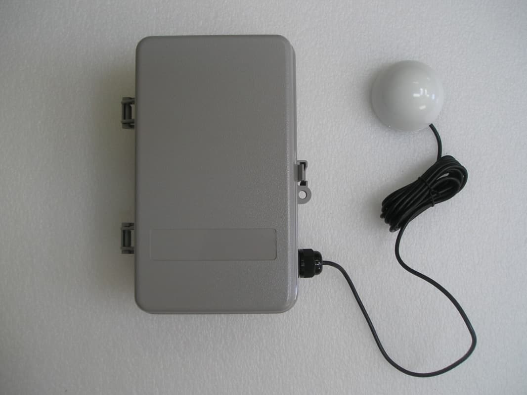
2ABMM-WPCPT6WIR
Dec 18, 2014WPCs are devices to control swim pool peripherals.
Equipment Class
DXX - Part 15 Low Power Communication Device Transmitter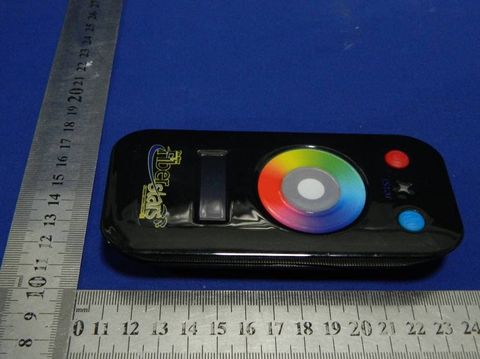
2ABMMISRMT
Jan 26, 2014RF Remoter
Equipment Class
DXX - Part 15 Low Power Communication Device Transmitter