2ABRC-BC300Emitter
Optoma Corporation
Click to zoom
Application Details
- Equipment Class
- DXX - Part 15 Low Power Communication Device Transmitter
- Date of Grant
- Feb 17, 2014
- Application Purpose
- Original Equipment
- Date of Application
- Feb 17, 2014
- Equipment Note
- Emitter
- Frequency Range
- 2440.00000000 - 2460.00000000
- Company
- Optoma Corporation
- Country
- Taiwan
Documents & Files
Document Text
Text extracted from the exhibit documents filed with the FCC. Open a document above to read the original.
Users Manual
1. Connect emitter to Optoma projector 2. Select VESA in projector OSD Optoma 3D Glasses – Quick Setup Guide 3. Be within the pairing zone Note: When using the glasses for the first time, it is recommended to charge the glasses for a minimum of three hours before use. When syncing the glasses for the first time, the glasses must be within pairing zone range. Charging the glasses 4.Turn on the glasses 2 d e n d e v m i e m w o i n c e g R z o n e d e p d a n i e r i n m g m o z c o e n R e 0 . 5 ~ 1 5 m 0~10m 3 4 3D Emitter LED Indicator Messages Searching for 3D signal Synced with 3D signal 3D Glasses LCD lens/LED Indicator Messages Power on/Searching with emitter Synced with emitter Pairing with emitter Power off Low Battery Charging Fully charged Flashing blue Solid blue Blue led blinks twice and turns off; LCD blinkslens twice Flashingand redblue Red led blinks and turns off LCD lens blinks twice every 5 seconds before shutting down Solid red Off Flashing blue Projector Emitter a b ONOFF Optoma 3D Glasses – Quick Setup Guide FCC Notice: This device complies with Part 15 of the FCC Rules. Operation is subject to the following two conditions: (1) This device may not cause harmful interference. (2) This device must accept any interference received, including interference that may cause undesired operation. NOTE: This equipment has been tested and found to comply with the limits for a Class B digital device, pursuant to Part 15 of the FCC Rules. These limits are designed to provide reasonable protection against harmful interference in a residential installation. This equipment generates uses and can radiate radio frequency energy and, if not installed and used in accordance with the instructions, may cause harmful interference to radio communications. However, there is no guarantee that interference will not occur in a particular installation. If this equipment does cause harmful interference to radio or television reception, which can be determined by turning the equipment off and on, the user is encouraged to try to correct the interference by one or more of the following measures: ---Reorient or relocate the receiving antenna. ---Increase the separation between the equipment and receiver. ---Connect the equipment into an outlet on a circuit different from that to which the receiver is connected. ---Consult the dealer or an experienced radio/TV technician for help. WARNING: Changes or modifications not expressly approved by the party responsible for compliance could void the user's authority to operate the equipment. IC Notice:This device complies with Canada Industry licence- exempt RSS standard(s). Operation is subject to the following two conditions: (1) this device may not cause interference. and (2) this device must accept any interference. Including interference that may cause undesired operation of the device. This device complies with RSS-310 of Industry Canada. Operation is subject to the condition that this device does not cause harmful interference. Le présent appareil est conforme aux CNR d'industrie Canada applicables aux appareils radio exem pts de licence L'exploitation est autorisée aux deux conditions suivantes: 1) I'appareil ne doit pas produire de brouillage, et 2) I'utillsateur de I'appareil doit accepterbrouillage radioélectrique subi meme si le brouillage est susceptible d'encompromettre le fonctionnement. mauvais fonctionnement de I'appareil. *繁體中文 使用隨附之線材(一端為2.5mm,另端為VESA 3-PIN mini DIN)將訊號發射器接駁至投影機後方之"3D SYNC OUT"端子埠。 註:確保連接投影機的訊號來源播放相容的3D影片格 式,3D 投影方式必須設定正確.(相容於HDMI 1.4的 3D格式一般選擇"自動"即可)。 3D訊號發射器搜尋3D訊號過程中,其LED燈號會以藍 色閃爍方式呈現;當搜尋到3D 訊號且確認成功後,燈 號會固定為藍色。 將3D眼鏡上的開關鍵撥至ON位置以打開您的3D眼 鏡,眼鏡上的紅色與藍色LED燈會開始交替閃爍。偵 測到正確3D 訊號時,即可正常運作&藍色燈號熄滅。 (1) (2) 3) 你現在可以順利觀看3D影片 (使用完畢後,請記得對3D 眼鏡充電) 如需更詳細資訊,請至Optoma 網站查詢說明 Optoma 3D 眼鏡 - 快速設定介紹 建議您在第一次使用前,至少對3D眼鏡充電三小時以上 (使用 USB/Mini USB線材充電,充電時眼鏡仍可使用)。 *简体中文 使用附赠线材(一端为2.5mm,另一端为VESA 3-PIN mini DIN)将信号发射器接至投影机后方的"3D SYNC OUT"端口处。 注:确保连接投影机的信号来源播放兼容的3D影片格 式,3D投影方式必须设定正确。(兼容HDMI 1.4的 3D格式一般选择“自动”即可) 在搜索3D信号过程中,发射器上的LED灯将会显示蓝 色并且不断闪烁;当搜索到3D信号时,LED将显示为 恒定的蓝色。 将3D眼镜上的开关键拨至ON位置以打开您的3D眼 镜,眼镜上的红色与蓝色LED灯会开始交替闪烁.侦测到 正确3D 讯号时,即可正常运作&蓝色灯号熄灭。 (1) (2) (3) 你现在可以顺利观看3D 影片了 (使用完毕后,请记住对3D眼镜充电) 如需更详细资讯,请到Optoma官方网站查询相关说明 Optoma 3D 眼镜 - 快速设定指南 建议您在第一次使用前,至少对3D 眼镜充电三小时以上(使 用USB/Mini USB 线材充电,充电时眼镜仍可使用) *한국어 제공된 케이블(2.5mm jack / VESA 3-PIN mini DIN)을 사용하여이미터와프로젝터뒤면의 '3D SYNC OUT'포트로연결하십시오. 주의사항: 프로젝터 호환되는 3D 소스에 연결하십시오. 3D 투사 방식이 정확한지 확인하십시오.(HDMI 1.4에 3D 콘텐츠가 제공되면 일반적으로 '자동'을 선택하십시오. 3D 신호를 검색하는 동안 이미터에있는 LED가 남색 으로 깜박입니다. 3D 신호가 감지되면, LED는 남색 으로 고정됩니다. 전원 스위치를 오프에서 온으로 전환하여 3D 안경을 켜십시오. LED가 남색과 적색 교대로 깜박입니다. 3D 신호가 감지되면 남색 LED가 꺼집니다. (1) (2) (3) 이제 3D 영상을 감상할 수 있습니다. (사용 완료후, 3D안경을 충전하는 것을 잊지 마세요.) 더욱 상세한 정보는 Optoma 웹사이트를 이용해 주십시 오. Optoma 3D 안경- 빠른 설정 가이드 *English 1.Connect emitter to Optoma Projector 2.Select VESA in projector OSD 3.Be within the pairing zone 4.Turn on the glasses Optoma 3D Glasses – Quick Setup Guide Note: 1.When using the glasses for the first time, it is recommended to charge the glasses for a minimum of three hours before use. 2.When syncing the glasses for the first time, the glasses must be within pairing zone range. *Français 1.Connecter l'émetteur au projecteur Optoma 2.Sélectionner VESA dans le menu du projecteur 3.Se placer dans la zone de synchronisation 4.Allumer les lunettes Recharger les lunettes Lunettes 3D Optoma - Guide d'installation rapide Note: 1.Avant la première utilisation des lunettes, il est recommandé de les charger pendant au moins trois heures. 2.Lors de la première synchronisation des lunettes avec le projecteur, les lunettes doivent être dans la zone de synchronisation. *Deutsch 1.Schließen Sie den Emitter an den Projektor an. 2.Wählen Sie VESA im Menü des Projektors aus. 3.Sie müssen sich innerhalb der Reichweite des Signals befinden. 4.Schalten Sie die Brille ein. Aufladen und Synchronisieren der Brille Optoma 3D Brille - Schnellstartanleitung Hinweis: 1.Es wird empfohlen, die Brille vor dem ersten Gebrauch für m…
Text truncated - open the document above for the full version.
External Photos
DONGGUAN NTC CO., LTD. FCC ID: 2ABRC-BC300 Report NO.: NTC1401059F DONGGUAN NTC CO., LTD. FCC ID: 2ABRC-BC300 Report NO.: NTC1401059F DONGGUAN NTC CO., LTD. FCC ID: 2ABRC-BC300 Report NO.: NTC1401059F DONGGUAN NTC CO., LTD. FCC ID: 2ABRC-BC300 Report NO.: NTC1401059F
ID Label/Location Info
Label Location
Internal Photos
DONGGUAN NTC CO., LTD. FCC ID: 2ABRC-BC300 Report NO.: NTC1401059F RF Antenna RF Chip DONGGUAN NTC CO., LTD. FCC ID: 2ABRC-BC300 Report NO.: NTC1401059F
Test Report
DONGGUAN NTC CO., LTD. Report No.: NTC1401059F FCC ID: 2ABRC-BC300 Page 2 of 22 Table of Contents 1. GENERAL INFORMATION ................................................................................................ 3 1.1 PRODUCT DESCRIPTION FOR EQUIPMENT UNDER TEST.................................................................... 3 1.2 RELATED SUBMITTAL(S) / GRANT (S) ................................................................................................ 4 1.3 TEST METHODOLOGY....................................................................................................................... 4 1.4 EQUIPMENT MODIFICATIONS............................................................................................................ 4 1.5 SUPPORT DEVICE............................................................................................................................ 4 1.6 TEST FACILITY AND LOCATION.......................................................................................................... 4 1.7 SUMMARY OF TEST RESULTS........................................................................................................... 5 2. SYSTEM TEST CONFIGURATION.................................................................................... 6 2.1 EUT CONFIGURATION...................................................................................................................... 6 2.2 SPECIAL ACCESSORIES.................................................................................................................... 6 2.3 DESCRIPTION OF TEST MODES......................................................................................................... 6 2.4 EUT EXERCISE................................................................................................................................6 3. CONDUCTED EMISSIONS TEST ...................................................................................... 7 3.1 TEST SET-UP (BLOCK DIAGRAM OF CONFIGURATION)..................................................................... 7 3.2 TEST CONDITION............................................................................................................................. 7 3.3 MEASUREMENT RESULTS................................................................................................................. 7 4. RADIATED EMISSION TEST........................................................................................... 10 4.1 TEST SET-UP (BLOCK DIAGRAM OF CONFIGURATION)................................................................... 10 4.2 MEASUREMENT PROCEDURE......................................................................................................... 11 4.3 LIMIT.............................................................................................................................................. 12 4.4 MEASUREMENT RESULTS ..................................................................................................... 13 5. 20DB BANDWIDTH.......................................................................................................... 17 5.1 MEASUREMENT PROCEDURE......................................................................................................... 17 5.2 TEST SET-UP (BLOCK DIAGRAM OF CONFIGURATION)................................................................... 17 5.3 MEASUREMENT RESULTS............................................................................................................... 17 6. BAND EDGE ....................................................................................................................20 6.1 MEASUREMENT PROCEDURE......................................................................................................... 20 6.2 LIMIT.............................................................................................................................................. 20 6.3 MEASUREMENT RESULTS............................................................................................................... 20 7. ANTENNA REQUIREMENT ............................................................................................. 21 7.1 MEASUREMENT PROCEDURE......................................................................................................... 21 7.2 MEASUREMENT RESULTS............................................................................................................... 21 8. TEST EQUIPMENT LIST.................................................................................................. 22 DONGGUAN NTC CO., LTD. Report No.: NTC1401059F FCC ID: 2ABRC-BC300 Page 3 of 22 1. GENERAL INFORMATION 1.1 Product Description for Equipment under Test This device is a 3D transmitter; it’s powered by DC 5V come from USB port. For more details features, please refer to User’s Manual. Manufacturer : Estar Display Tech. Co., Ltd. Address : No.71 Donggang 3 Road, Kecheng District, Quzhou City, Zhejiang Province, China Frequency range: : 2440-2460MHz Modulation : MSK Number of Channel : 1 Antenna Type : PCB Antenna Gain : 1dBi (declaration by manufacturer) Power Supply : DC 5V come from USB port Model name : BC300 Note: :N/A DONGGUAN NTC CO., LTD. Report No.: NTC1401059F FCC ID: 2ABRC-BC300 Page 4 of 22 1.2 Related Submittal(s) / Grant (s) This submittal(s) (test report) is intended for FCC ID: 2ABRC-BC300 filing to comply with Section 15.249 of the FCC Part 15 (2012), Subpart C Rule. 1.3 Test Methodology Both AC mains line-conducted and radiated emission measurements were performed according to the procedures in ANSI C63.4 (2009). Radiated emission measurement was performed in semi-anechoic chamber and conducted emission measurement was performed in shield room. For radiated emission measurement, preliminary scans were performed in the semi-anechoic chamber only to determine the worst case modes. All radiated tests were performed at an antenna to EUT …
Text truncated - open the document above for the full version.
Test Setup Photos
DONGGUAN NTC CO., LTD. FCC ID: 2ABRC-BC300 Report NO.: NTC1401059F Conducted Emission Radiated Emission
Contact Information
Applicant
francine wu(Product Manager)
Test Firm
Dongguan NTC Co.,Ltd.,sunm lv sunm lv
[email protected]86-769-22022444
Technical Specifications
| # | Rule Parts | Frequency Range | Power Output |
|---|---|---|---|
| 1 | 15C | 2.44 GHz - 2.46 GHz | - |
Other Applications from Optoma Corporation
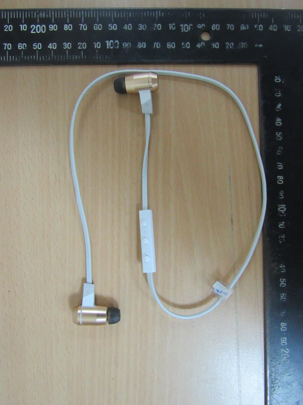
2ABRC-APBEL
Jul 29, 2015Bluetooth earphones
Equipment Class
DSS - Part 15 Spread Spectrum Transmitter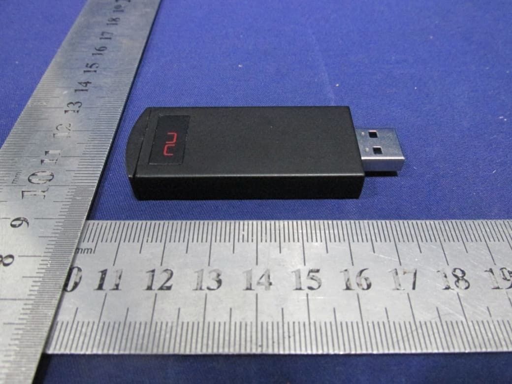
2ABRC-ALBTRZG
Feb 09, 2015apt-X Bluetooth receiver
Equipment Class
DSS - Part 15 Spread Spectrum Transmitter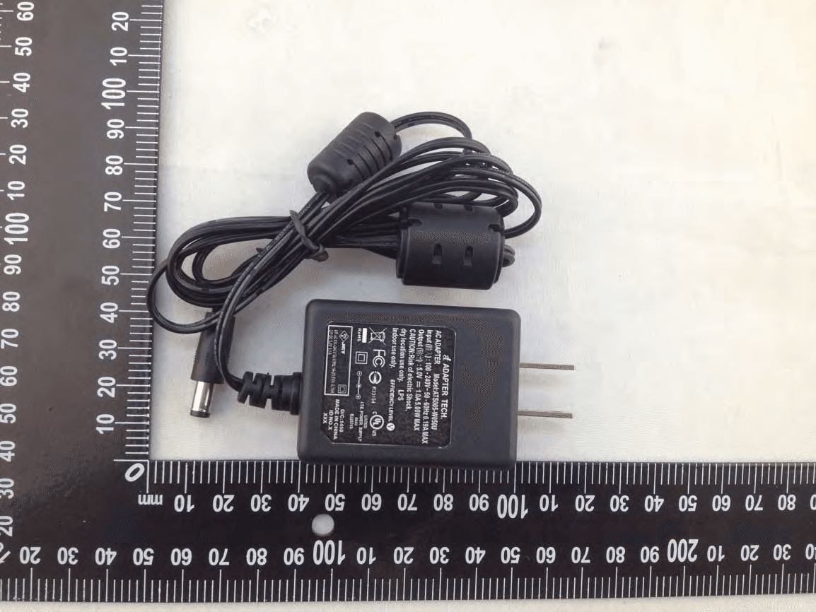
2ABRC-ALWDCNZZ
Jan 15, 2015Wireless Digital to Analog Converter
Equipment Class
DTS - Digital Transmission System