2ABTA301XData Transfer Device
Health & Life Co., Ltd.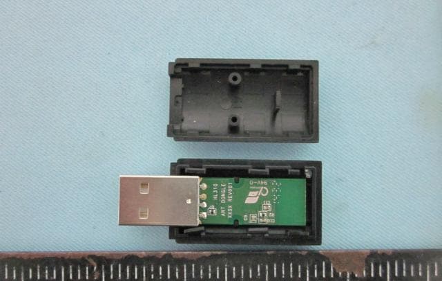
Click to zoom
Application Details
- Equipment Class
- DXX - Part 15 Low Power Communication Device Transmitter
- Date of Grant
- Nov 17, 2014
- Application Purpose
- Original Equipment
- Date of Application
- Nov 17, 2014
- Equipment Note
- Data Transfer Device
- Frequency Range
- 2403.00000000 - 2478.00000000
- Company
- Health & Life Co., Ltd.
- Country
- Taiwan
Documents & Files
Document Text
Text extracted from the exhibit documents filed with the FCC. Open a document above to read the original.
Users Manual
HL301 Data Transfer Device INSTRUCTION MANUAL Uploading your data to Cloud Server -After finish your sport training, follow the below instructions to upload your data to server for analyzing Step A: Please go to http://www.fitsignal.com.tw , click “Register”, key in “Application” and click “sent”. Operating System: Windows capacity Recommended Internet Browser: IE 9 or above/ FIREFOX/ GOOGLE CHROME Step B: Back to the index page, click “Driver & Tools”, downloading FitSignalSetup program. Step C: Unzip the file, execute and install the “FitSignalSetupVx.xx.exe” Step C-1: Click “Next” Step C-2: Click “I Agree” Step C-3: Click “Install” Step C-4: Choose “Run FitSignalBeacon 2.0”, and click “Finish” to complete installation. Step C-5: After installation, the window will jump out the above interface, click “Confirm” on Dialog Box, if not, click the “” icon. Step C-6: Fill in your Account (E-mail), click “OK” and finish. Step C-7: From now on, the “Start Menu” and “Desktop” will have “FitSignalBeacon” shortcut to start the program. Fitsignalbeacon Step D: Plug your data transfer device into your PC through USB port, and start “FitSignalBeacon” program *Attention! ★ Please keep your data transfer device in acceptable distance (≦3 meters) between your PC. ★ If you transmit large amounts of data, it may take you few minutes. You cannot taking any sport training during data transmission. ★ Please upload your workout data regularly to analyze your workouts. ★ Keep away from electronic or other electromagnetic source. ★ Do not use the Data Transfer Device in extremely low (less than -10 °C/14 °F) and high (more than 50 °C/122 °F) environments. Specifications Model Number: HL301 Dimensions: 50 X 20.5 X 10.6 mm (L x W x H) Weight: 7.5g Transmitting Rage: 3M Operation Environment: -10 °C ~ 50 °C (14 °F ~ 122 °F) Radio Frequency: 2.4GHz, Dynastream ANT+ Sport PC Interface: Windows XP/ Windows 7 Administrative Regulations on Low Power Radio Waves Radiated Devices This Data Transfer Device is in accordance with Administrative Regulations on Low Power Radio Waves Radiated Devices and qualified this regulation. User shall follow the telecommunication regulation to avoid penalty. If user intends to carry this Data Transfer Device to other country, please follow the local regulations and restrictions. According to Administrative Regulations on Low Power Radio Waves Radiated Devices regulations: Article 12 Without permission granted by the DGT, any company, enterprise, or user is not allowed to change frequency, enhance transmitting power or alter original characteristic as well as performance to an approved low power radio-frequency devices. Article 14 The low power radio-frequency devices shall not influence aircraft security and interfere legal communications; If found, the user shall cease operating immediately until no interference is achieved. The said legal communications means radio communications is operated in compliance with the Telecommunications Act. The low power radio-frequency devices must be susceptible with the interference from legal communications or ISM radio wave radiated devices. FCC Declaration Declaration of Conformity Data Transfer Device declares that this product is in compliance with the Directive 1999/5/EC and other relevant requirements. FEDERAL COMMUNICATIONS COMMISSION INTERFERENCE STATEMENT This equipment has been tested and found to comply with the limits for a Class B digital device, pursuant to Part 15 of the FCC Rules. These limits are designed to provide reasonable protection against harmful interference in a residential installation. This equipment generates, uses and can radiate radio frequency energy and, if not installed and used in accordance with the instructions, may cause harmful interference to radio communications. However, there is no guarantee that interference will not occur in a particular installation. If this equipment does cause harmful interference to radio or television reception, which can be determined by turning the equipment off and on, the user is encouraged to try to correct the interference by one or more of the following measures: Reorient or relocate the receiving antenna. Increase the separation between the equipment and the receiver. Connect the equipment into an outlet on a circuit different from that to which the receiver is connected. Consult the dealer or an experienced radio/TV technician for help. CAUTION: To assure continued FCC compliance: Any changes or modifications not expressly approved by the grantee of this device could void the user's authority to operate the equipment. This device complies with Part 15 of the FCC Rules. Operation is subject to the following two conditions: (1) this device may not cause harmful interference, and (2) this device must accept any interference received, including interference that may cause undesired operation. P/N: XXXXXXXXX VER:A001 YYYYMMDD
External Photos
ETC Report No. : 14-09-RBF-006-07 Sheet 1 of 5 Sheets FCC ID 2ABTA301X: CONSTRUCTION PHOTOS OF EUT (A) EUT 1. 2. ETC Report No. : 14-09-RBF-006-07 Sheet 2 of 5 Sheets FCC ID 2ABTA301X: CONSTRUCTION PHOTOS OF EUT 3. 4. ETC Report No. : 14-09-RBF-006-07 Sheet 3 of 5 Sheets FCC ID 2ABTA301X: CONSTRUCTION PHOTOS OF EUT 5. 6. ETC Report No. : 14-09-RBF-006-07 Sheet 4 of 5 Sheets FCC ID 2ABTA301X: CONSTRUCTION PHOTOS OF EUT 7. 8.
Internal Photos
ETC Report No. : 14-09-RBF-006-07 Sheet 4 of 5 Sheets FCC ID 2ABTA301X: CONSTRUCTION PHOTOS OF EUT 7. 8. ETC Report No. : 14-09-RBF-006-07 Sheet 5 of 5 Sheets FCC ID 2ABTA301X: CONSTRUCTION PHOTOS OF EUT 9. 10.
RF Exposure Info
According to KDB 447498 section 4.3.1, the 1-g SAR test exclusion thresholds at test separation distance ≤ 50 mm are determined by: [(max. power of channel, including tune-up tolerance, mW) / (min. test separation distance,mm)] ·[ √f(GHz)] ≤ 3.0 The max. average power of channel, including tune-up tolerance(mW) is 2.51 mW @ 2403MHz (With Tune-up tolerance), The min. test separation distance (mm) is 5 mm, So, [(max. power of channel, including tune-up tolerance, mW) / (min. test separation distance, mm)] ·[√f(GHz)] = 0.78 < 3.0 (With Tune-up tolerance). Therefore, standalone SAR measurements are not required for both head and body. Signature___________________________________ Name/Title: S. S. Liou / Section Manager, EMC Testing Department II TEL: +886‐2‐2602‐3052 Email: [email protected]
Test Report
I FCC Part 15 EMI TEST REPORT of E.U.T. : Data Transfer Device MODEL : HL301 FCC ID. : 2ABTA301X Frequency Range : 2403MHz~2478MHz for APPLICANT : HEALTH & LIFE Co., Ltd. ADDRESS : 9F, No. 186, Jian Yi Road, Zhonghe District, New Taipei City, Taiwan Test Performed by ELECTRONICS TESTING CENTER, TAIWAN NO. 34. LIN 5, DINGFU VIL., LINKOU DIST., NEW TAIPEI CITY, TAIWAN, 24442, R.O.C. TEL : (02)26023052 FAX: (02)26010910 http : // www.etc.org.tw; e-mail : [email protected] Report Number : 14-09-RBF-006-07 . ETC Report No. : 14-09-RBF-006-07 FCC ID : 2ABTA301X II TEST REPORT CERTIFICATION Applicant : HEALTH & LIFE Co., Ltd. 9F, No. 186, Jian Yi Road, Zhonghe District, New Taipei City, Taiwan Manufacturer : HEALTH & LIFE (Suzhou) Co., Ltd. NO.1428 XIANG JIAN ROAD, SUZHOU NEW DISTRICT SUZHOU CITY 215129, CHINA Description of EUT a) Type of EUT : Data Transfer Device b) Trade Name : N/A c) Model No. : HL301 d) Power Supply : Power From PC f) Frequency Range : 2403MHz~2478MHz Regulation Applied : FCC Rules and Regulations Part 15 Subpart C I HEREBY CERTIFY THAT: The data shown in this report were made in accordance with the procedures given in ANSI C63.4, and the energy emitted by the device was founded to be within the limits applicable. I assume full responsibility for accuracy and completeness of these data. Note: 1. The result of the testing report relate only to the item tested. 2. The testing report shall not be reproduced expect in full, without the written approval of ETC. Summary of Tests Test Results Radiated Emission Pass Conducted Emission Pass Band Edge Requirement Pass ETC Report No. : 14-09-RBF-006-07 FCC ID : 2ABTA301X III Date Test Item Received : Sep.09, 2014 Date Test Campaign Completed : Oct. 30, 2014 Date of Issue : Nov. 07, 2014 Test Engineer : ( Jiapeng Chen, Engineer ) Approve & Authorized Signer : S. S. Liou, Section Manager EMC Dept. II of ELECTRONICS TESTING CENTER, TAIWAN ETC Report No. : 14-09-RBF-006-07 FCC ID : 2ABTA301X IV Table of Contents Page Cover Page........................................................................................................I TEST REPORT CERTIFICATION...........................................................................II Table of Contents...............................................................................................IV 1 GENERAL INFORMATION ...................................................................................................... 1 1.1 Product Description...................................................................................................................... 1 1.2 Characteristics of Device ............................................................................................................. 1 1.3 Test Methodology ........................................................................................................................ 1 1.4 Test Facility.................................................................................................................................. 1 2 PROVISIONS APPLICABLE ..................................................................................................... 2 2.1 Definition ..................................................................................................................................... 2 2.2 Requirement for Compliance ....................................................................................................... 3 2.3 Restricted Bands of Operation ..................................................................................................... 5 2.4 Labeling Requirement .................................................................................................................. 5 2.5 User Information .......................................................................................................................... 6 3. SYSTEM TEST CONFIGURATION ......................................................................................... 7 3.1 Justification .................................................................................................................................. 7 3.2 Devices for Tested System........................................................................................................... 7 4 RADIATED EMISSION MEASUREMENT.............................................................................. 8 4.1 Applicable Standard ..................................................................................................................... 8 4.2 Measurement Procedure............................................................................................................... 8 4.3 Measuring Instrument ................................................................................................................ 10 4.4 Radiated Emission Data ............................................................................................................. 11 4.4.1 RF Portion ......................................................................................................................................... 11 4.4.2 Other Emissions ................................................................................................................................. 17 4.5 Field Strength Calculation ......................................................................................................... 19 4.6 Photos of Radiation Measuring Setup........................................................................................20 5 CONDUCTED EMISSION MEASUREMENT ....................................................................... 21 5.1 Standard Applicable ................................................................................................................... 21 5.2 Measurement Procedure............................................................................................................. 21 5.3 Conducted Emission Data ..............................…
Text truncated - open the document above for the full version.
Test Setup Photos
ETC Report No. : 14-09-RBF-006-07 Sheet 20 of 32 Sheets FCC ID 2ABTA301X: 4.6 Photos of Radiation Measuring Setup ETC Report No. : 14-09-RBF-006-07 Sheet 25 of 32 Sheets FCC ID 2ABTA301X: 5.6 Photos of Conduction Measuring Setup
Contact Information
Applicant
Albert Lee(President)
Test Firm
Taiwan Testing and Certification CenterAnderson Ku
Technical Specifications
| # | Rule Parts | Frequency Range | Power Output |
|---|---|---|---|
| 1 | 15C | 2.40 GHz - 2.48 GHz | - |
Other Applications from Health & Life Co., Ltd.
2ABTAHNL85CE1
Aug 24, 2021Automatic Upper Arm Blood Pressure Monitor
Equipment Class
DTS - Digital Transmission System
2ABTAHNL85DM
May 02, 2021Automatic Upper Arm Blood Pressure Monitor
Equipment Class
DTS - Digital Transmission System
2ABTAHNL85CG1
Mar 09, 2021Automatic Upper Arm Blood Pressure Monitor
Equipment Class
DTS - Digital Transmission System
2ABTAHNL85A1Z
Jan 31, 2021Automatic Upper Arm Blood Pressure Monitor
Equipment Class
DTS - Digital Transmission System
2ABTAHNL15AU
Jun 15, 2020Automatic Wrist Blood Pressure Monitor
Equipment Class
DTS - Digital Transmission System