2ABTYLPTV560 W UHF ATSC DTV Transmitter
Anywave Communication Technologies, Inc.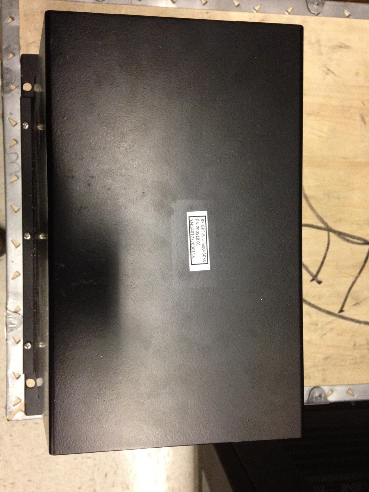
Click to zoom
Application Details
- Equipment Class
- TBC - Licensed Broadcast Station Transmitter
- Date of Grant
- Aug 27, 2014
- Application Purpose
- Original Equipment
- Date of Application
- Mar 27, 2014
- Equipment Note
- 560 W UHF ATSC DTV Transmitter
- Frequency Range
- 614.00000000 - 806.00000000
- Country
- United States
Documents & Files
Document Text
Text extracted from the exhibit documents filed with the FCC. Open a document above to read the original.
Users Manual
ANYWAVE PA-560W User Manual Version 1.0 ACT-5XU-560-A-C January 14, 2014 PA-560W User Manual Version 1.0 01/14/2014 Page 2 of 11 Copyright Notice Copyright © Anywave Communication Technologies, Inc. 2013, All rights reserved. No part of this publication may be reproduced, translated, transcribed, stored in a retrieval system, or transmitted into any form or by any means, without the express written permission of Anywave Communication Technologies, Inc. Disclaimer Information provided by Anywave Communication Technologies is believed to be accurate and complete; however, no liability can be assumed for its use. The information contained in this publication is subject to change without notice. Anywave Communication Technologies Inc. 300 Knightsbridge Parkway, Suite 150, Lincolnshire, IL 60069 Tel: +1 (847) 415-2258 Fax: +1 (847) 415-2112 http://www.anywavecom.com/en/ PA-560W User Manual Version 1.0 01/14/2014 Page 3 of 11 Contents 1 Product Appearance ................................................................................................................ 4 1.1 Front Panel ..................................................................................................... 4 1.2 Back Panel ..................................................................................................... 6 2 Specifications .......................................................................................................................... 8 3 Control Interface ..................................................................................................................... 9 3.1 Local Control Interface .................................................................................. 9 3.2 Web Interface ............................................................................................... 10 3.3 Serial Port Interface ..................................................................................... 11 PA-560W User Manual Version 1.0 01/14/2014 Page 4 of 11 1 Product Appearance 1.1 Front Panel RF Button Press the RF button to turn the RF signal ON (inside blue light will light up). Press the RF button again to turn the RF signal OFF (inside blue light will be off). LED_PWR Blue light will be on when the DC voltage of internal power supply is within the normal range (48 VDC ~ 52 VDC). Blue light will flash when the DC voltage of internal power supply is out of the normal range (48 VDC ~ 52 VDC). Blue light will be off when the external power supply is turned off, or internal power supply module does not work. LED_FWD Blue light will be on when RF_OUT has power output. Blue light will be off when the RF button is turned off, or the PA enters the auto-protection mode and therefore shuts down its RF output. There are several situations which will result in auto-protection mode, such as the input power is too high, the reflected power is too high, or the temperature is too high. LED_RFL Red light will be off when the reflected power is normal. (Threshold configurable) Red light will be on when the reflected power is too high. It may be caused by no load connected to port RF_OUT. In this case, the PA will enter auto-protection mode and there will be no RF output. PA-560W User Manual Version 1.0 01/14/2014 Page 5 of 11 LED_TEMP Red light will be off when temperature is normal (≤ 140 o F). Red light will be on when system temperature is too high (> 140 o F). It may be caused by a broken cooling system. In this situation, the PA will enter auto-protection mode and there will be no RF output. Note: 1) The front fan covers can be removed to clean the air intake path. No screw driver is needed, and no disassembly of the PA is required. 2) When a warning occurs and the PA enters auto-protection mode, the only way to clear this state is to cycle power on the PA module once the problem(s) is resolved. Otherwise all warning LEDs will remain on even if the problem(s) no longer exists. PA-560W User Manual Version 1.0 01/14/2014 Page 6 of 11 1.2 Back Panel RF_IN Connector: N Impedance: 50 Ω Rated Power: +1 dBm ± 1 dB @ 700 W output Note: If input power from RF_IN is lower than rated input value, the output power will be lower than rated output power accordingly. This is because the PA has a fixed gain of 56 dB ± 1 dB. If the input level from RF_IN is higher than the rated value, it will result in RF output distortion and performance deterioration. If the input level is more than 1 dB higher than the rated value or the output power is higher than 720 W, it may trigger the current-limiting function of the internal power supply. The PA will enter the auto-protection mode, and there will be no RF output. RF_OUT Connector: 7/16 DIN Impedance: 50 Ω Rated Power: 700 W (ATSC) before filter Note: RF_OUT must be connected with a load, otherwise the PA will enter the auto-protection mode and there will be in no RF output. Please note that the PA is designed to withstand any load conditions, including no load at all, without damaging the PA. However it is strongly suggested to have a load connected with proper impedance. PA-560W User Manual Version 1.0 01/14/2014 Page 7 of 11 MONITOR (loop out of RF_OUT) Connector: BNC female Impedance: 50 Ω Rated Power: 0 dBm ± 3 dB @ 700 W Note: It is OK to leave this port open without load. RS232-A Connector: DB9-M Note: Connected to REMOTE (RS232) port of ACT-5X, which is used for control and communication between the PA and the exciter. RS232-B: Connector: DB9-M Note: Reserved RJ45 Connector: 10M/100M Ethernet Note: For customers’ remote control to the PA. Note: 1) The back fan covers can also be removed to clean the air intake path. No screw driver is needed, and no disassembly of the PA is required. PA-560W User Manual Version 1.0 01/14/2014 Page 8 of 11 2 Specifications Environment Operation Temperature: -10 o C ~ +60 o C (+14 o F ~ +140 o F) Operation Humidity: 20 % ~ 90 % (non-cond…
Text truncated - open the document above for the full version.
Attestation Statements
March 26, 2014 Federal Communications Commission Office Of Engineering Technology To Whom It May Concern: ATTESTATION STATEMENT I hereby certify the measurements were executed and test results were recorded in accordance with accepted engineering practices and do constitute an accurate representation of the product performance of the documented LPTV transmitter. President Greg Best Consulting, Inc. 9223 N. Manning Ave. Kansas City, MO 64157 816-792-2913
Cover Letter(s)
June 2, 2014 CONFIDENTIALITY REQUEST LETTER ANYWAVE COMMUNICATIONS TECHNOLOGIES, INC LPTV TRANSMITTER TECHNICAL DATA Pursuant to FCC 0.457(d) and 0.459 of the FCC Rules long-term confidentiality is requested due to the fact that the applicant, Anywave Communications Technologies, Inc., considers certain information to be submitted as trade secret information. Specifically, internal construction photos and schematics submitted as exhibits for type certification for the above transmitter are not normally available to anyone outside of company employees. The specific files needing confidentiality are identified as: 560W_PA_Sch.pdf Exciter_Sch.pdf 560 W PA INTERNAL CONSTRUCTION PHOTO.pdf Exciter_Internal_Photo.PDF Anywave Communications Technologies, Inc. realizes that Internal Construction Photos are not normally included within confidential material. However, the unique nature of the design of Anywave Communications Technologies Inc. exciter and UHF power amplifiers provides a compelling argument to retain internal construction photos of the amplifier as confidential. The following justification applies. Schematics are held confidential because a competitor can use the information to potentially reproduce the assembly described by the schematic and make a copy available for sale. Likewise, the actual printed circuit boards of the exciter and power amplifier have microstrip transmission lines to tune and optimize the performance of the circuits. In effect, the transmission lines are components just like any other part within the schematics. These microstrip lines and arrangement of components are easily visible from viewing internal photographs of the exciter and UHF amplifier construction. Treating the photos without confidentiality makes the microstrip lines and the arrangement of components available to potential competitors and is like giving a portion of the schematics to possible competitors. Indeed, the microstrip lines and arrangement of the components are often the most critical decisions in the design process. It is for this reason that Anywave Greg Best Consulting, Inc. 9223 N. Manning Ave. Kansas City, MO 64157 816-792-2913 l Page 2 June 2, 2014 Communications Technologies, Inc. believes that public access to the internal construction photos is potentially harmful to its business. Anywave Communications Technologies, Inc. has gone to great expense to develop their equipment and they could be financially harmed if another competitor were to copy the products using the schematics and internal construction photo information and make them available for sale. The internal construction photos and schematic information contained within the exhibits submitted with this type certification application are not supplied with customer documentation. Because of the nature of the schematics and internal construction photos, redacted documents are not possible. At a minimum, a period of 5 years is necessary for confidentiality for these documents. Regards,
Cover Letter(s)
Company Initial: Employee Initial: Anywave Communication Technologies Inc. Proprietary Information and Inventions Agreement As a condition of my employment with Anywave Communication Technologies Inc., its parents, subsidiaries, affiliates, successors or assigns (together “the Company”), and in consideration of my employment with the Company and my receipt of the compensation now and hereafter paid to me by the Company, I agree: 1. to disclose and assign to the Company as its exclusive property, all inventions and technical or business innovations or contributions, including computer software, developed or conceived by me solely or jointly with others during the period of my employment, (1) that are along the lines of the business, work or investigations of the Company or its affiliates to which my employment relates or as to which I may receive information due to my employment, or (2) that result from or are suggested by any work which I may do for the Company, or (3) that are otherwise made through the use of the Company time, facilities or materials. 2. to execute all necessary papers and otherwise provide proper assistance (at the Company’s expense), during and subsequent to my employment, to enable the Company to obtain for itself or its nominees, patents, copyrights, or other legal protection for such inventions or innovations in any and all countries. 3. to make and maintain for the Company adequate and current written records of all such inventions or innovations. 4. to hold in strictest confidence, and not to use, except for the benefit of the Company, or to disclose to any person, firm or corporation, any Confidential Information of the Company. I understand that “Confidential Information” means any Company proprietary information, technical data, trade secrets or know-how, marked “company confidential” or stated in verbal, including but not limited to: research, product plans, products, services, customer lists and customers (including but not limited to: customers of the Company on whom I called or with whom I became acquainted during the term of my employment), markets, software, developments, inventions, processes, formulas, technology, designs, drawings, engineering, hardware configuration information, marketing, finances and other business information disclosed to me by the Company either directly or indirectly in writing, orally or by drawings or observation of parts or equipment. 5. during my employment with the Company, I will not improperly use or disclose any proprietary information or trade secrets of any former employer or other person or entity and that I will not bring onto the premises of the Company any unpublished document or proprietary information belonging to any such employer, person or entity unless consented to in writing by such employer, person, or entity. 6. upon any termination of my employment, I will deliver to the Company (and will not keep in my possession, recreate or deliver to anyone else) any and all devices, records, data, notes, reports, proposals, lists, correspondence, specifications, drawings blueprints, sketches, materials, equipment, other documents or property, or reproductions of any aforementioned items developed by me pursuant to my employment with the Company or otherwise belonging to the Company, its successors, or assigns. I agree to execute any proper oath or verify any proper document required to carry out the terms of this Agreement. I represent that I have not entered into, and I agree I will not enter into, any oral or written agreement in conflict with the foregoing. Company Initial: Employee Initial: Anywave Communication Technologies Inc. I agree that it would be impossible or inadequate to measure and calculate the Company's damages from any breach of the covenants set forth in this Agreement. Accordingly, I agree that if I breach any of these covenants, the Company will have available, in addition to any other right or remedy available, the right to obtain an injunction from a court of competent jurisdiction restraining such breach or threatened breach and to specific performance of any such provision of this Agreement. This Agreement sets forth the entire agreement and understanding between the Company and me relating to the subject matter herein and merges all prior discussions between us. No modification of or amendment to this agreement, nor any waiver of any rights under this agreement, will be effective unless in writing signed by the party to be charged. Any subsequent change or changes in my duties, salary or compensation will not affect the validity or scope of this Agreement. PAUL DADIAN _________________ ______________________________ ____________ Print Name Signature Date ______________________________ PERRY PRIESTLEY – CEO ________ Witness (the Company Representative) Position or Title of Witness
External Photos
560W ATSC TX External Construction photos Anywave Communication Technologies Inc. CONFIDENTIAL ATSC 560W TX PA (front & back) ACT-5XU-560-A-C Anywave Communication Technologies Inc. CONFIDENTIAL ATSC 560W TX PA (sides-right & left) ACT-5XU-560-A-C Anywave Communication Technologies Inc. CONFIDENTIAL ATSC 560W TX PA (top and bottom) ACT-5XU-560-A-C Anywave Communication Technologies Inc. CONFIDENTIAL ATSC 560W TX PA (inside-top&bottom) ACT-5XU-560-A-C Anywave Communication Technologies Inc. CONFIDENTIAL 560W TX Exciter (front & back) ACT-5XU-560-A-C Anywave Communication Technologies Inc. CONFIDENTIAL 560W TX 600W BPF (Front) ACT-5XU-560-A-C Anywave Communication Technologies Inc. CONFIDENTIAL 560W TX 600W BPF (Back) ACT-5XU-560-A-C Anywave Communication Technologies Inc. CONFIDENTIAL 560W TX 600W BPF (side-left) ACT-5XU-560-A-C Anywave Communication Technologies Inc. CONFIDENTIAL 560W TX 600W BPF (side-right) ACT-5XU-560-A-C Anywave Communication Technologies Inc. CONFIDENTIAL 560W TX 600W BPF (top) ACT-5XU-560-A-C Anywave Communication Technologies Inc. CONFIDENTIAL 560W TX 600W BPF (bottom) ACT-5XU-560-A-C Anywave Communication Technologies Inc. CONFIDENTIAL ANYWAVE Anywave Communication Technologies Inc. 300 Knightsbridge Parkway, Suite 150 Lincolnshire, IL 60069, USA Tel: +1 847 415 2258 www.anywavecom.com/en
ID Label/Location Info
Anywave Communication Technologies FCCID Label –LPTV ATSC TX Anywave Communication Technologies, Inc. 2 LPTV FCCID Label 1 in 2 in Contact Information Anywave Communication Technologies Inc. 300 Knightsbridge Parkway, Suite 150 Lincolnshire, IL 60069 +1 847 415 2258 www.anywavecom.com/en Anywave Communication Technologies, Inc. 3
Operational Description
ANYWAVE ATSC 560W DTV Transmitter Operational Description CONFIDENTIAL ATSC 560W DTV TX SCHEMATIC Anywave Communication Technologies, Inc. - CONFIDENTIAL (Preliminary) Page 2 of 4 Contents 1 TX System Schematic ...................................................................... 3 2 Theory of Operation ......................................................................... 4 ATSC 560W DTV TX SCHEMATIC Anywave Communication Technologies, Inc. - CONFIDENTIAL (Preliminary) Page 3 of 4 1 TX System Schematic The ATSC 560W DTV transmitter is composed of three basic components, a digital exciter, 560W PA, and 600W BPF as outlined below. 600W BPF To Ant / Load IN OUT To PC for Remote Ctrl TS Input 560W PA AC Mains 110-220V, 20A Single phase Exciter ATSC 560W DTV TX SCHEMATIC Anywave Communication Technologies, Inc. - CONFIDENTIAL (Preliminary) Page 4 of 4 2 Theory of Operation The ATSC 560W DTV transmitter is conceptually simple to understand and easy to operate. The Transmitter operates on single phase 110 or 220V, 20A AC Mains service. A standard ATSC ASI input stream is provided to one of the BNC connectors located on the rear panel of the Exciter. The Exciter performs the appropriate FEC and Signal Processing to modulate a standard 19.39 Mbps ATSC TS to produce an RF output at the desired channel frequency. The modulated RF output signal from the Exciter is fed to the RF Input of the 560W PA. The PA module contains 4x BLF888A devices that amplify the RF signal to produce ~700W of output power (560W after the BPF). The amplified output signal is connected from the PA output to the input of a Harmonic filter (if required) before entering the channel mask BPF. The output of the 600W BPF connects to the Antenna feed to radiate the DTV signal on-air. The Exciter receives two feedback signals from FWD and REV couplers located on the BPF. These before and after BPF feedback signals are used by the Exciter to provide automatic Linear and Non-Linear pre-correction of the ideal 8-VSB forward path signal. The Exciter communicates with the 560W PA via an RS-232 serial link which allows the Exciter to display the operating parameters of the PA (including FWD Pwr, VSWR, voltages, and currents of the PA power supplies, etc.) on the Exciter front panel LCD. The Exciter acts as the main TX user interface for monitoring and control via its local front panel and remote web interfaces.
Parts List/Tune Up Info
Anywave Communication Technologies Configuration :ACT-5XU-560-A-C 560W ATSC UHF TV Transmitter System SYSTEM BOM (CONFIDENTIAL) Anywave Communication Technologies, Inc. -CONFIDENTIAL 2 560W TX UHF –SYSTEM BOM Item #DescriptionQTYModel #Part # 15X Exciter1ACT-5XU-A-C100004.01 2560W PA1ACT-560U-A-C100510.01 3600W6-pole BPF 7/161RF-BPF-6-U-600200518.01 41KW UHF 7/16 DINHarmonic Filter1RF-HF-U-716D-1000200601.01 Contact Information Anywave Communication Technologies Inc. 300 Knightsbridge Parkway, Suite 150 Lincolnshire, IL 60069 +1 847 415 2258 www.anywavecom.com/en Anywave Communication Technologies, Inc. -CONFIDENTIAL 3
Parts List/Tune Up Info
Anywave Communication Technologies LPTV Quick Start (Setup & Turn On) Guide 2014/5/302 LPTV Equip List –(typical) Item #DescriptionQTYModel #Part # 1560W PA1ACT-560U-A-C100510.01 25X Exciter1ACT-5XU-A-C100004.01 3600W UHF 6-pole BPF 7-161RF-BPF-6-U-600-###S200518.01 43 ftN-N RF cable (Excto PA)1CBL-N-M-RF-3201208.01 52KW UHF 7/16 LPF1RF-HF-U-716D-2000 200602.01 63 ft 7/16-7/16 DIN (PA to LPF))1CBL716-M-RF-3201211.01 76 ft 7/16-7/16 DIN (LPF to BPF))1CBL716-M-RF-6201212.01 83 ftBNC-BNC (BPF BEFORE to ExcRF_INB)1CBL-BNC-M-RF-3201205.01 9 3 ftBNC-BNC (DirCoupler Afterto Exc RF_INA)1CBL-BNC-M-RF-3201205.01 10 3ftRS232-Serial Cable (Exciter REMOTE D9 to PA RS232-A)1CBL-RS232-3201201.01 113 ftEthernetcable (CAT5) (included with PA)1CBL-ETH-3201202.01 Interconnect Diagram: (typical) 2014/5/30 To PC (Web GUI) (192.168.1.143) 3 In Out Load/Ant Directional Coupler L P F BPF Quick Start Guide –Turning On Your System (1) 2014/5/304 1.Unpack the equipment and make sure you received all materials outline in the equipment list on p2. (note: All Single PA TX systems ship with an AC power cord included with every Exciter and PA. The PA shipment also includes an RS232 cable, for Exciterto PA communications, and a CAT5 Ethernet cable, for Exciter to PC built-in web interface communications.) 2.With all equipment still turned OFF, please make the cable connections according to the interconnect diagram on p3. Also connect any external test equipment, power meters, spectrum analyzers, etc. to desired system test points(note: Exciter LCD %FWD, SNR, LID, UID metrics are based off the After BPF feedback sample (RF IN A BNC) on rear panel) 3.Turn on Exciter and set Exciter to LOCAL mode, set ADPC to OFF (SYSTEM submenu), be sure RF is Off, and AGC is OFF (RF submenu) (Please refer to your Exciter User Manual for help with menu navigation and detailed operation of the exciter). 4.Check and set the Exciter Input selection (TS for Transmitter, Tuner for Translator) (under SYSTEM submenu) 5.Check and set the Exciter TX frequency (this is your Center channel frequency under FREQ submenu) 6.Set Exciter RF POWER level to -15bBm (under RF submenu) 7.Double Check that the PA and/or BPF is properly connected to the Antenna feed or suitable Load, then turn the PA ON via PA rear panel breaker, then press the front panel PA RF On/Off button -which should turn BLUE when ON 8.Visit the PAC menu on the Exciter (under Advanced submenu) and verify that the voltages and currents are showing real values and not 0s 9.Under the RF submenu, with the Exciter RF still reduced, and AGC OFF, turn the Exciter RF ON, verify Exciter RF LED turns ON front panel of Exciter 10.Bring the power up slowly to half rated output power (measured via power meter (with proper coupling value set) and Directional coupler after the BPF) 11.Check uncorrected SNR and LID/UID on Exciter front panel, with BPF (17<TSNR<20dB, LID/UID >40dB), without BPF (TSNR>27dB, LID/UID >40dB) 12.You are now ready to perform Linear and Non-Linear corrections. (Please refer to the Exciter User Manual for detailed instructions on running corrections).Before running corrections, it is important to verify proper feedback signal levels. There are two feedback signal samples used to compute corrections. “RF In A” (After BPF) is used to calculate Linear correction coefficients while “RF IN B” (Before BPF) is used to compute the Non-Linear correction coefficients. 13.Navigate to the Exciter “DPD” submenu in the Advanced User menu (simultaneously press Left and Right buttons, then simultaneously press UP and Down buttons). Be sure the value of Feedback Sample Signal Input (FSSI) for both A (after) and B (before) reads somewhere between 45% and 75% -which roughly corresponds to a value of -15 to -5 dBm as measured on a power meter (note: the FSSI indicator toggles between A and B and will “flash” when the signal level is out of range, too high or too low). Add or remove the appropriate attenuator padding to achieve feedback signal levels in the desired range. Quick Start Guide –Turning On Your System (2) 14.Check and set the value of PDT (set to 3) and CFR (set to F) in the DPD Advanced Menu (Note: CFR=F means NO CFR, CFR=0, means maximum CFR) 15.Navigate to the Exciter “SYSTEM” submenu and select UPDATE under ADPC to run corrections. The exciter will then proceed through 4 stages of correction, automatically computing Linear and Non-Linear corrections, and saving the coefficients into non-volatile memory upon completion. The correction process typically takes from 8-10 minutes to complete while real-time performance metrics of SNR and Shoulder performance are displayed on the LCD. 16.Verify that SNR and Shoulders meet spec on the Exciter front panel at half power 17.Bring the power up slowly to full output power (560W measured via power meter (with proper coupling value set) and Directional coupler after the BPF) 18.Navigate to your ACT-5X Exciter “PAC” submenu in the Advanced User menu (simultaneously press Left and Right buttons, then simultaneously press UP and Down buttons) and verify the reading of PA_FWD power (note: this is the output power of the PA before the LPF + BPF and not your FWD System power, which will include the loss of your LPF + BPF). 19.Check and verify feedback samples at full power (FSSI A and B) are in the range of 45-75% (adjust attenuator pads as needed) 20.Run corrections via UPDATE under ADPC in the Exciter SYSTEM submenu 21.Verify RF Performance metrics are in spec (SNR > 27dB, Shoulders > 47 dB) on the front panel screen of the exciter (change the value of CFR or rerun correction if necessary to meet specs) 22.Allow system to operate at full output power for 30 minutes and then return to the Exciter “RF” submenu and make any required adjustments to output power by slightly changing the value of POWER up or down to achieve 100% system FWD power. 23.Navigate to the CAL setting under the AD3 Advanced submenu and select CAL then press OK to calibrate the FWD …
Text truncated - open the document above for the full version.
Test Report
1 ANYWAVE MODEL LPTV 560W DTV TRANSMITTER TECHNICAL REPORT TABLE OF CONTENTS PAGE Introduction 2 Test Equipment Configuration 3 RF Output Power Measurements – 560 Watts 4 Frequency Stability Measurements 5 Emission Mask Compliance Measurements – 560 Watts 6 Adjacent Channel Measurements 10 Harmonic & Spurious Measurements 12 GPS Band Filter Attenuation 15 Cabinet Radiation Measurements 16 RF Output Power Measurements – 125 Watts 18 Emission Mask Compliance Measurements – 125 Watts 19 Adjacent Channel Measurements 22 Harmonic & Spurious Measurements 23 Test Equipment 26 Summary and Conclusion 26 9223 N. Manning Ave. Kansas City, MO 64157 816-792-2913 Greg Best Consulting, Inc. 2 TEST REPORT LPTV TRANSMITTER TECHNICAL REPORT The following information is provided to support the technical performance of the Anywave model LPTV DTV transmitter. The information is supplied for broadcast service according to applicable portions of Part 74 and Part 2 of the FCC Rules. The information in this report is provided in support of certification that the transmitter meets the appropriate requirements. Measurements outlined below were recorded of spectrum and other data to demonstrate compliance. The tests executed for the LPTV transmitter include: 1. Power Output Measurements 2. Frequency stability tests versus AC input voltage and temperature 3. Measurements to demonstrate the transmitter meets the DTV emission mask as specified in FCC Rule 74.794 (a) (2) (ii) and 74.794 (b) (1). 4. Measurement of cabinet radiation for spurious and harmonic emission as specified in FCC Rule 2.1053 and Rule 2.1057 Measurements for power output and emission mask compliance were conducted at power output levels of both 560 watts and 125 watts and thus this is the range over which type certification for this transmitter is sought. The test equipment used for the measurements is listed at the end of this document. LPTV
Test Report
3 Note: The coupling factor of directional coupler #2 was determined to be 56.7 dB at channel 36. FIGURE 1—TEST EQUIPMENT CONFIGURATION LPTV Exciter LPTV Power Amp Directional Coupler #1 Emission Mask Filter Directional Coupler #2 Bandstop Filter R & S ETL Agilent E4404B R & S NRP-Z51 Power Meter High Pass Filter Dummy Load Personal Computer
Test Report
4 RF Power Output Measurements – 560 Watts The equipment was configured as shown in Figure 1. The coupling factor of directional coupler #2 was calibrated at the center frequency of the channel 36 DTV signal of 605 MHz. The coupling value was 56.7 dB from the directional coupler so an offset of 56.7 dB was added to the reading of the power meter. Average power was measured with the R & S NRP-Z51 power sensor and displayed on the personal computer using the Power Viewer program. The indicated reading is shown below. Figure 2—Power Meter Reading at Nominal Transmitter Power Calculation of Output Power and DC Input Power: An offset of 56.7 dB from the directional coupler was added to the indicated reading from the Power Viewer program. The actual value of 0.79 dBm was measured on the Power Viewer display and then the offset value from the directional coupler of 56.7 dBm was added to display the correct value of 57.49 dBm or 561 watts. In order to determine the total DC power to the final RF amplifier stage, currents and voltage from the final amplifier stage were measured and multiplied together. With this operating power, measured transmitter final amplifier voltage is 49.1 VDC and final amplifier current is 41.6 Amps. The DC power was calculated to be 2042 watts. 5 FREQUENCY STABILITY For temperature stability measurements, the transmitter exciter was placed inside a Tenney T10C temperature chamber equipped with a Watlow temperature controller and thermometer. The frequency stability of the transmitter is determined solely by the exciter so no additional power amplifiers were used or needed for this test. The frequency stability was measured versus temperature and versus line voltage. The temperature range was measured from 0 °C to 40 °C in steps of 10 °C or less. The channel 36 pilot frequency was used for the test. The output frequency of the channel 36 pilot signal of the exciter was measured with an R&S ETL DTV receiver and spectrum analyzer with a 0.1 PPM stability reference oscillator and the signal counter was activated to provide a resolution of 0.1 Hz. The exciter synthesizer board was working in internal mode, so it was not locked to an external reference. The exciter was switched on at 0 °C and allowed to stabilize from 14:35 to 15:05. The temperature was raised during the period between 15:05 and 16:25. The temperature was stabilized at each measurement increment for a minimum of 15 minutes. The test results are located below. FREQUENCY STABILITY VERSUS TEMPERATURE RESULTS The line voltage was adjusted for nominal voltage and the frequency was recorded. Then the line voltage was adjusted to 85% and 115% of the nominal voltage using a variac and the frequen…
Text truncated - open the document above for the full version.
Contact Information
Applicant
Ted Karam(Vice President)
Technical Contact
Greg Best Consulting, Inc.Greg Best
[email protected]816-792-2913
9223 N. Manning Avenue · Kansas City, Missouri · United States
Technical Specifications
| # | Rule Parts | Frequency Range | Power Output | Emission | Tolerance |
|---|---|---|---|---|---|
| 2 | 74 | 614 MHz - 806 MHz | 560 W | 6M00K1D | 1000 Hz |
Other Applications from Anywave Communication Technologies, Inc.
2ABTYMHPTV
Apr 06, 20208800W UHF ATSC DTV Transmitter
Equipment Class
TBC - Licensed Broadcast Station Transmitter
2ABTYMPTV
Aug 17, 20141 kW DTV ATSC Transmitter
Equipment Class
TBC - Licensed Broadcast Station Transmitter