2ABU8240824122408, 2412
Nuvectra Corporation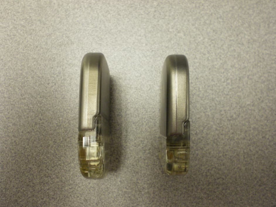
Click to zoom
Application Details
- Equipment Class
- TNT - Licensed Non-Broadcast Transmitter Worn on Body
- Date of Grant
- Apr 09, 2014
- Application Purpose
- Original Equipment
- Date of Application
- Apr 07, 2014
- Equipment Note
- 2408, 2412
- Frequency Range
- 402.15000000 - 404.85000000
- Company
- Nuvectra Corporation
- Country
- United States
Documents & Files
Document Text
Text extracted from the exhibit documents filed with the FCC. Open a document above to read the original.
Users Manual
Algovita ™ Spinal Cord Stimulation System Stimulator Models 2408 and 2412 For IPG replacement Implant Manual for Stimulator IPG implant.indb 13/3/14 8:46 AM Algovita™ is a trademark of QIG Group, LLC CoreGuard™ is a trademark of Greatbatch, Inc. Refer to the Information for Prescribers Manual for indications, contraindications, warnings, precautions, adverse events, and related information. FCC Information (US Only) The following is communications regulation information about the Algovita Implantable Pulse Generator (IPG). 2408 and 2412 IPG FCC ID: 2ABU824082412 These devices comply with part 15 of the FCC Rules. Operation is subject to the following two conditions: (1) These devices may not cause harmful interference, and (2) These devices must accept any interference received including interference that may cause undesired operation. Important: Changes and modifications to these products not authorized by Algostim, LLC could void the FCC certification and negate your authority to operate these products. IPG implant.indb 23/3/14 8:46 AM Algovita Spinal Cord Stimulation System Stimulator Model 2408 and 2412 Implant Manual 3 Contents Explanation of Symbols Used on Packaging 5 Component Description 7 Package Contents 8 Component Sterilization 8 About this IPG Replacement Manual 8 Implant Procedure 8 Preparing for Surgery 8 Preoperative IPG Preparation 9 Explanting the IPG 13 Connecting the Leads or Extensions to the New IPG 13 Checking System Integrity 16 Implanting the New IPG 16 Completing the Implant Procedure 17 Patient Counseling Information 17 SCS System Implant: IPG Replacement 17 Registration Form and Temporary Patient ID Card 18 Returning Explanted Components 18 Algostim Customer Service 18 Specifications 19 Wireless Information 20 Algovita SCS System Component Compatibility 21 IPG implant.indb 33/3/14 8:46 AM 4 Stimulator Model 2408 and 2412 Implant Manual IPG implant.indb 43/3/14 8:46 AM Algovita Spinal Cord Stimulation System Implant Manual for Stimulator 5 Explanation of Symbols Used on Packaging SymbolExplanation 20XX Conformité Européenne (European Conformity). This symbol means that the device fully complies with European Directive AIMD 90/385/EEC. Caution: Federal Law (USA) restricts this device to sale on or by the order of a physician. Consult instructions for use Caution Serial number Catalog number Model number Authorized representative in Europe Use by date Distributed by Manufacturer Temperature limit Keep dry Sterilized using ethylene oxide Do not resterilize Do not reuse IPG implant.indb 53/3/14 8:46 AM 6 Implant Manual for Stimulator Explanation of Symbols Used on Packaging SymbolExplanation Keep away from sunlight Do not use if package is damaged Phone Recycle Contents IPG: 3 connector ports with 8 channels each IPG: 2 connector ports with 12 channels each IPG implant.indb 63/3/14 8:46 AM Algovita Spinal Cord Stimulation System Implant Manual for Stimulator 7 Component Description The Algovita™ Stimulator Model 2408 or 2412 (Figure 1) is part of the Algovita Spinal Cord Stimulation (SCS) System, a rechargeable, 24-electrode, SCS system for the treatment of chronic pain. 1 2 1 2 3 ,LLC ,LLC Figure 1. Algovita Stimulator Model 2408 and Model 2412 The Algovita Stimulator is the implantable pulse generator (IPG) for the Algovita SCS System. In addition to the IPG, the implanted components of the SCS system consist of percutaneous leads or paddle leads with optional extensions. During the intraoperative test, an external pulse generator (EPG) is used in place of the IPG. The clinician programs the IPG and the EPG using a Clinician Programmer. The patient adjusts the system using either of 2 patient programmers. Algovita IPGs are 24-channel rechargeable IPGs. Each channel allows the system 1 active electrode. The channels are distributed over 2 or 3 connector ports, depending on the IPG model. • Algovita Stimulator Model 2408 (3x8 channel)—Three connector ports accommodate 1 to 3 percutaneous leads, with each lead allowing up to 8 active electrodes. • Algovita Stimulator Model 2412 (2x12 channel)—Two connector ports accommodate 1 or 2 percutaneous or paddle leads, with each lead allowing up to 12 active electrodes. The IPG delivers stimulation using independent current distribution, a technology that allows variable amounts of current to be delivered to each active electrode. The IPG battery is a deep discharge recovery battery with CoreGuard™ technology. Even if the patient allows the battery to completely discharge, the battery can be recharged with the Algovita Programmer Charger. IPG implant.indb 73/3/14 8:46 AM 8 Implant Manual for Stimulator Package Contents Package Contents • Stimulator Model 2408 (3x8) or Model 2412 (2x12) • Torque wrench • Port plugs (3 for Model 2408, 2 for Model 2412) • Product literature • Temporary patient ID card • Implant registration form and business reply envelope Component Sterilization The implantable and surgical accessory components were sterilized with ethylene oxide prior to shipment. The SCS system sterile components are intended for single use only and must not be resterilized. Caution: Do not resterilize a system component or reimplant an explanted system component because of risk of infection or malfunction. About this IPG Replacement Manual This manual provides the instructions for the replacement of an Algovita Stimulator Model 2408 or 2412. For complete instructions on implanting an IPG as part of a system implant, refer to the system manual packaged in the lead kit. Implant Procedure Implanting clinicians should be thoroughly familiar with this manual and all other product labeling. Caution: Do not place the charging paddle on an unhealed wound. The charging paddle is not sterile. Contact with an unhealed wound may result in an infection. Preparing for Surgery Before opening the sterile pack, verify the following on the sterile pack label: • IPG—Model number and use-by date IPG implant.indb 83/3/14 8:46 AM Algovita Spina…
Text truncated - open the document above for the full version.
Cover Letter(s)
WTD 13.4.9 FCC Compliance Opinion QIGG0006 Information about the Applicant Grantee (Company Name) Algostim, LLC FCC Contact Person Bernard Bosley Address 10675 Naples Street NE City, State, Zip Blaine, MN 55449 Job Number QIGG0006 Model 2408, 2412 FCC ID 2ABUB24082412 Agent Approval Type Original Equipment Class TNT - Licensed Non-Broadcast Transmitter Worn on Body Rule Part 95I Overview The Algostim Algovita models 2408 and 2412 are implantable pulse generators used to treat chronic pain. The devices use an integrated antenna and contain an RF transceiver that transmits and receives in the MedRadio band on 402-405 MHz. Confidentiality requested for allowed files. Request is properly addressed and referenced. Short term confidentiality requested. Recommendation All items have been resolved and completed to my satisfaction; therefore I recommend this application for approval. Signature Dave Tolman, TCB Committee 4/2/2014
External Photos
External Photos Model 2408 Model 2412 Front Back Top Side Bottom Side
ID Label/Location Info
GBM Material # 1010933 Rev 03 Algostim Material # 1210-001625 Rev 04 (01)00000000000000(17)YYMMDD(21)0000000000 (01)00000000000000(17)YYMMDD(21)0000000000 GS1-128 Barcode Algovita™ Spinal Cord Stimulation System Stimulator (2x12) 24 Channel, 24 Electrode, Constant Current Stimulator For use with Algovita™ Spinal Cord Stimulation System component models: leads 112x-xx, 3000-xx, 3101-xx; extensions 5212-xx; programmers 4100, 4200, and 4500. -DD -DD (1) Stimulator (1) Torque Wrench (2) Port Plug Product Literature Registration Form MADE IN USA Algostim, LLC 10675 Naples Street NE Blaine, MN 55449 763.786.7400 www.algostim.com Authorized Representative in Europe Emergo Europe Molenstraat 15 2513 BH The Hague The Netherlands (31) (0) 70 345-8570 20XX YYYY-MM-DD MODEL 2412 XXXX-XX-XX XXXXXXXXX FCC ID: 2ABU824082412
ID Label/Location Info
GBM Material # 1010933 Rev 03 Algostim Material # 1210-001623 Rev 04 (01)00000000000000(17)YYMMDD(21)0000000000 (01)00000000000000(17)YYMMDD(21)0000000000 GS1-128 Barcode Algovita™ Spinal Cord Stimulation System Stimulator (3x8) 24 Channel, 24 Electrode, Constant Current Stimulator For use with Algovita™ Spinal Cord Stimulation System component models: leads 108x-xx; extensions 5208-xx; programmers 4100, 4200 and 4500. -DD -DD (1) Stimulator (1) Torque Wrench (3) Port Plug Product Literature Registration Form 20XX MADE IN USA Algostim, LLC 10675 Naples Street NE Blaine, MN 55449 763.786.7400 www.algostim.com Authorized Representative in Europe Emergo Europe Molenstraat 15 2513 BH The Hague The Netherlands (31) (0) 70 345-8570 YYYY-MM-DD MODEL 2408 XXXX-XX-XX XXXXXXXXX FCC ID: 2ABU824082412
Operational Description
3 March 2014 Dear Sir or Madam: We, QiG Group ( a wholly owned subsidiary of Greatbatch, Inc.), located at 1771 East 30 th Street, Cleveland, Ohio 44114, are providing the following Antenna Information for the Algovita Spinal Cord Stimulation (SCS) Implantable Pulse Generator (IPG) RF telemetry communications feature available on Models 2408 and 2412 in accordance with the TCB technical requirements: The Algovita Models 2408 and 2412 Spinal Cord Stimulation (SCS) Implantable Pulse Generator (IPG) use a permanently attached wire loop (magnetic dipole) antenna encased in a urethane and silicone header. The antenna is connected to the intentional radiator via two ceramic-isolated feed-through pins in the titanium enclosure. The approximate gain of the antenna is – 25 dBi. Access to the antenna connections of the intentional radiator is prohibited by the enclosure. Section 47 CFR 15.203 of the FCC rules state the use of a permanently attached antenna shall be considered sufficient to comply with the requirements of this section. PG Enclosure with Integral Antenna Header Assembly (Front) Custom Wire Loop Antenna IPG Enclosure with Integral Antenna Header Assembly (Rear) Antenna Connection Feed-through Pin Terminals
RF Exposure Info
In FCC KDB 447498 General RF Exposure Guidance D01 v05r01, Section 4.2.4, the FCC provides a power threshold, below which implanted devices are excluded from SAR measurement or numerical simulation: "Transmitters implanted in the body of a user When the aggregate of the maximum power available at the antenna port and radiating structures of an implanted transmitter, under all operating circumstances, is ≤ 1.0 mW, SAR test exclusion may be applied. The maximum available output power requirement and worst case operating conditions must be supported by power measurement results and fully justified in a SAR analysis report, in lieu of the SAR measurement or numerical simulation, according to design and implementation requirements of the device." Since both the radiated output power and conducted output power are well below 1.0 mW, this device is excluded from SAR measurement or numerical simulation. FCC ID: 2ABU824082412 is compliant with FCC RF Exposure requirements.
Test Report
QiG Group IPG, Models 2408 and 2412 FCC 95I:2013 Report #: QIGG0006 Report Prepared By Northwest EMC Inc. NORTHWEST EMC – (888) 364-2378 – www.nwemc.com California – Minnesota – Oregon – New York – Washington WTD 12.5.23 CERTIFICATE OF TEST Last Date of Test: October 8, 2013 QiG Group Model: IPG Model 2408 and Model 2412 Emissions Test Description Specification Test Method Pass/Fail Radiated Power (EIRP) FCC 95I:2013, FCC 2.1046:2013 ANSI/TIA/EIA-603-C:2004 Pass Spurious Radiated Emissions FCC 95I:2013, FCC 2.1053:2013 ANSI/TIA/EIA-603-C:2004 Pass Receiver Spurious Emissions FCC 15.109:2013 ANSI C63.4:2009 Pass Emission Bandwidth FCC 95I:2013, FCC 2.1049:2013 ANSI/TIA/EIA-603-C:2004 Pass Emission Mask FCC 95I:2013, FCC 2.1049:2013 ANSI/TIA/EIA-603-C:2004 Pass Frequency Stability FCC 95I:2013, FCC 2.1055:2013 ANSI/TIA/EIA-603-C:2004 Pass Deviations From Test Standards None Approved By: Tim O'Shea, Lab Manager NVLAP Lab Code: 200881-0 This report must not be used to claim product certification, approval, or endorsement by NVLAP, NIST, or any agency of the federal government of the United States of America. Product compliance is the responsibility of the client, therefore the tests and equipment modes of operation represented in this report were agreed upon by the client, prior to testing. This Report may only be duplicated in its entirety. The results of this test pertain only to the sample(s) tested. The specific description is noted in each of the individual sections of the test report supporting this certificate of test. REV 2012.08.02 REVISION HISTORY Revision Number Description Date Page Number 00 None Barometric Pressure The recorded barometric pressure has been normalized to sea level. REV 2012.05.24 ACCREDITATIONS AND AUTHORIZATIONS United States FCC - Designated by the FCC as a Telecommunications Certification Body (TCB). Certification chambers, Open Area Test Sites, and conducted measurement facilities are listed with the FCC. A2LA - Accredited by A2LA to ISO / IEC Guide 65 as a product certifier. This allows Northwest EMC to certify transmitters to FCC and IC specifications. NVLAP - Each laboratory is accredited by NVLAP to ISO 17025 Canada IC - Recognized by Industry Canada as a Certification Body (CB). Certification chambers and Open Area Test Sites are filed with IC. European Union European Commission – Validated by the European Commission as a Conformity Assessment Body (CAB) under the EMC directive and as a Notified Body under the R&TTE Directive. Australia/New Zealand ACMA - Recognized by ACMA as a CAB for the acceptance of test data. Korea KCC / RRA - Recognized by KCC’s RRA as a CAB for the acceptance of test data. Japan VCCI - Associate Member of the VCCI. Conducted and radiated measurement facilities are registered. Taiwan BSMI – Recognized by BSMI as a CAB for the acceptance of test data. NCC - Recognized by NCC as a CAB for the acceptance of test data. Singapore IDA – Recognized by IDA as a CAB for the acceptance of test data. Hong Kong OFTA – Recognized by OFTA as a CAB for the acceptance of test data. Vietnam MIC – Recognized by MIC as a CAB for the acceptance of test data. Russia GOST – Accredited by Certinform VNIINMASH, CERTINFO, SAMTES, and Federal CHEC to perform EMC and Hygienic testing for Information Technology products to GOST standards. SCOPE For details on the Scopes of our Accreditations, please visit: http://www.nwemc.com/accreditations/ REV 2013.03.8 MEASUREMENT UNCERTAINTY Measurement Uncertainty When a measurement is made, the result will be different from the true or theoretically correct value. The difference is the result of tolerances in the measurement system that cannot be completely eliminated. To the extent that technology allows us, it has been our aim to minimize this error. Measurement uncertainty is a statistical expression of measurement error qualified by a probability distribution. A measurement uncertainty estimation has been performed for each test per our internal quality document WP 342. The estimation is used to compare the measured result with its "true" or theoretically correct value. The expanded measurement uncertainty (K=2) for each test is listed below. Our measurement data meets or exceeds the measurement uncertainty requirements of the applicable specification; therefore, the test data can be compared directly to the specification limit to determine compliance. The calculations for estimating measurement uncertainty are based upon ETSI TR 100 028 (or CISPR 16-4-1 as applicable), and are available upon request. The following table represents the Measurement Uncertainty (MU) budgets for each of the tests that may be contained in this report. Test + MU - MU Frequency Accuracy (Hz) 0.12 -0.01 Amplitude Accuracy (dB) 0.49 -0.49 Conducted Power (dB) 0.41 -0.41 Radiated Power via Substitution (dB) 0.69 -0.68 Temperature (degrees C) 0.81 -0.81 Humidity (% RH) 2.89 -2.89 Field Strength (dB) 3.80 -3.80 AC Powerline Conducted Emissions (dB) 2.94 -2.94 REV 2013.06.28 FACILITIES Oregon Labs EV01-12 22975 NW Evergreen Pkwy Hillsboro, OR 97124 (503) 844-4066 California Labs OC01-13 41 Tesla Irvine, CA 92618 (949) 861-8918 New York Labs NY01-04 4939 Jordan Rd. Elbridge, NY 13060 (315) 685-0796 Minnesota Labs MN01-08 9349 W Broadway Ave. Brooklyn Park, MN 55445 (763) 425-2281 Washington Labs NC01-05,SU02,SU07 19201 120 th Ave. NE Bothell, WA 98011 (425) 984-6600 VCCI A-0108 A-0029 A-0109 A-0110 Industry Canada 2834D-1, 2834D-2 2834B-1, 2834B-2, 2834B-3 2834E-1 2834C-1 NVLAP NVLAP Lab Code: 200630-0 NVLAP Lab Code: 200676-0 NVLAP Lab Code: 200761-0 NVLAP Lab Code: 200881-0 NVLAP Lab Code: 200629-0 WTD 12.5.23 PRODUCT DESCRIPTION IPG Client and Equipment Under Test (EUT) Information Company Name: QiG Group Address: 10675 Naples Street NE City, State, Zip: Blaine, MN 55449 Test Requested By: Lisa Jorgenson Model: IPG Model 2408 and Model 2412 First Date of Test: September 25, 2013 Last Date of Test: October 8, 2013 Receipt Date of Samples: S…
Text truncated - open the document above for the full version.
Test Setup Photos
photo ER 001.jpg ER 002.jpg Radiated Power (EIRP) PSA-ESCI 2012.12.14 photo ER 003.jpg ER 004.jpg Radiated Power (EIRP) PSA-ESCI 2012.12.14 photo ER 005.jpg ER 006.jpg Radiated Power (EIRP) PSA-ESCI 2012.12.14 photo ER 007.jpg ER 008.jpg Radiated Power (EIRP) PSA-ESCI 2012.12.14 photo ER 001.jpg ER 002.jpg Spurious Radiated Emissions PSA-ESCI 2012.12.14 photo ER 003.jpg ER 004.jpg Spurious Radiated Emissions PSA-ESCI 2012.12.14 photo ER 005.jpg ER 006.jpg Spurious Radiated Emissions PSA-ESCI 2012.12.14 photo ER 007.jpg ER 008.jpg Spurious Radiated Emissions PSA-ESCI 2012.12.14 photo ER 001.jpg ER 002.jpg Receiver Spurious Emissions PSA-ESCI 2012.12.14 photo ER 003.jpg ER 004.jpg Receiver Spurious Emissions PSA-ESCI 2012.12.14 photo ER 005.jpg ER 006.jpg Receiver Spurious Emissions PSA-ESCI 2012.12.14 photo ER 007.jpg ER 008.jpg Receiver Spurious Emissions PSA-ESCI 2012.12.14 Emission Bandwidth XMit 2013.08.15 NORTHWEST Emission Bandwidth PsaTx 2013.08.16 EMC DIRECT 001.jpg DIRECT 002.jpg Emission Bandwidth Emissions Mask XMit 2013.08.15 NORTHWEST Emissions Mask PsaTx 2013.08.16 EMC DIRECT 001.jpg DIRECT 002.jpg Emissions Mask Frequency Stability XMit 2013.08.15 NORTHWEST Frequency Stability PsaTx 2013.08.16 EMC FS (1).JPG FS (2).JPG Frequency Stability
Contact Information
Applicant
Victoria Scheitlin(Senior Regulatory Affairs Specialist)
Test Firm
Northwest EMC, Inc.Greg Kiemel
Technical Specifications
| # | Rule Parts | Frequency Range | Power Output | Emission | Tolerance |
|---|---|---|---|---|---|
| 1 | 95I | 402.15 MHz - 404.85 MHz | 0.10 µW | 254KF1D | 14.3000000000 ppm |
Other Applications from Nuvectra Corporation
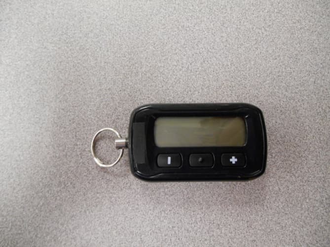
2ABU84100
Aug 25, 20144100
Equipment Class
DXX - Part 15 Low Power Communication Device Transmitter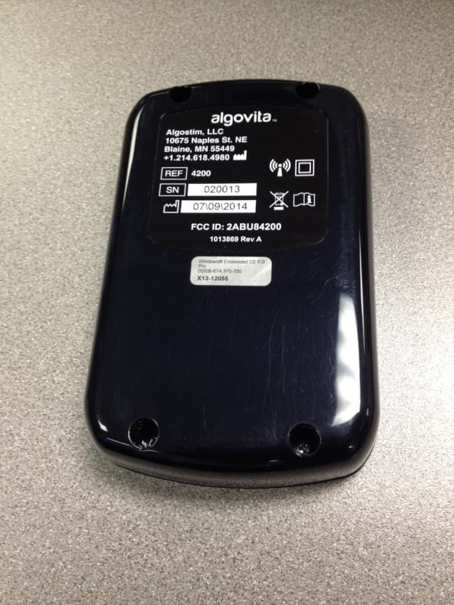
2ABU84200
Jul 23, 20144200
Equipment Class
TNT - Licensed Non-Broadcast Transmitter Worn on Body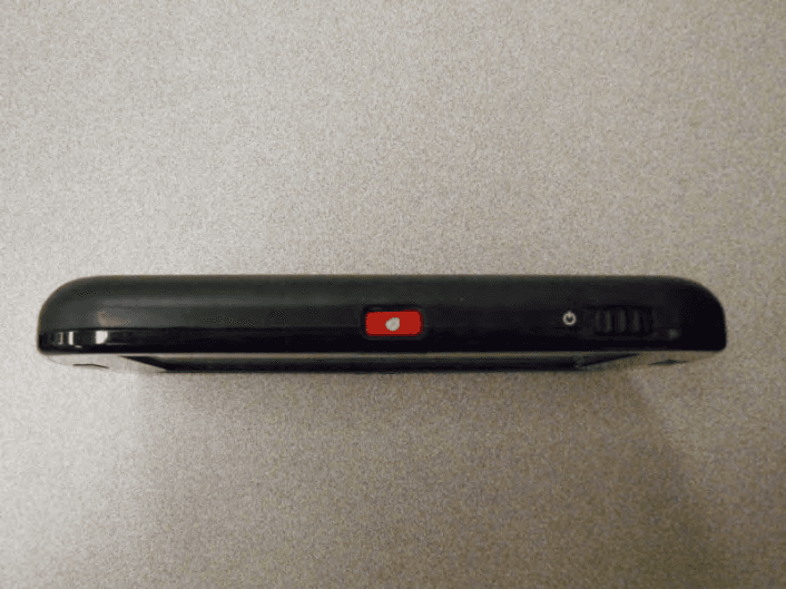
2ABU84500
Jul 23, 20144500
Equipment Class
DXX - Part 15 Low Power Communication Device Transmitter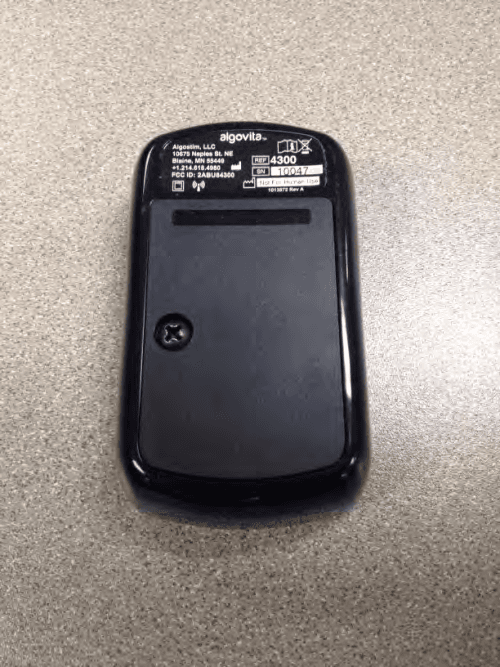
2ABU84300
Jul 23, 20144300
Equipment Class
TNT - Licensed Non-Broadcast Transmitter Worn on Body