2ABU845004500
Nuvectra Corporation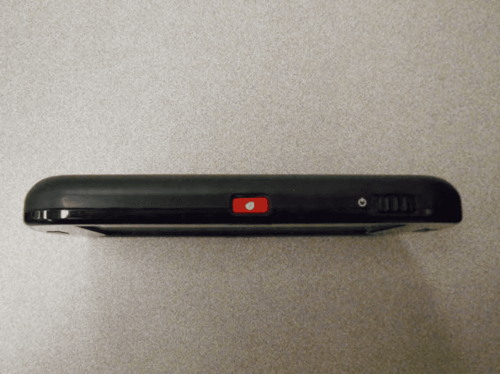
Click to zoom
Application Details
- Equipment Class
- DXX - Part 15 Low Power Communication Device Transmitter
- Date of Grant
- Jul 23, 2014
- Application Purpose
- Original Equipment
- Date of Application
- Jul 23, 2014
- Equipment Note
- 4500
- Frequency Range
- 2450.00000000 - 2450.00000000
- Company
- Nuvectra Corporation
- Country
- United States
Documents & Files
Document Text
Text extracted from the exhibit documents filed with the FCC. Open a document above to read the original.
Cover Letter(s)
WTD 13.4.9 FCC Compliance Opinion QIGG0010 Information about the Applicant Grantee (Company Name) Algostim, LLC FCC Contact Person Bernard Bosley Address 10675 Naples Street Northeast City, State, Zip Blaine, MN 55449 Job Number QIGG0010 - 4500 Model 4500 FCC ID 2ABU84500 Agent Approval Type Original Equipment Class DXX – Part 15 Low Power Communications Device TNT – Licensed Non-Broadcast Transmitter Worn on Body Rule Part 15.249, 95I Overview This application is for the original approval of Algostim, LLC's model 4500 Clinician Programmer in the Medical Device Radiocommunication Service. The model 4500 is a patient device used for commanding and querying Algostim pulse generators models 2408 IPG and 2412 IPG and Model 4300 EPG. The device communicates with the programmers in the 402 - 405 MHz MedRadio band under FCC rule part 95I. The device transmits a wake up signal in the 2.4 GHz band under rule part 15.249. Confidentiality requested for allowed files. Request is properly addressed and referenced. Short term confidentiality requested. Radiated Power on Grant Per 95.639(f)(1) the maximum permissible EIRP is 25 uW. Per 95.627(g)(3), compliance may be determined with a field strength measurement. The FCC conversion formula that equates the 25 uW EIRP limits to the 18.2 mV/m limit at 3 meters uses the Friis transmission equation modified with a 6 dB contribution due to ground plane reflection. Applying that equation: EIRP = ((V/m/2*3)^2/30, the maximum reported field strength of the fundamental emission is 85.1 dBuV/m at 3 meters, which equals 0.0000244W (EIRP). The field strength of the fundamental measurements are found in Intertek Test Report 101277992MIN-001C page 9 of 38. Recommendation All items have been resolved and completed to my satisfaction; therefore I recommend this application for approval. Signature Dave Tolman, TCB Committee 7/8/2014
Cover Letter(s)
FCC Home | Search | RSS | Updates | E-Filing | Initiatives | Consumers | Find People Office of Engineering and Technology Subject: Response to Inquiry to FCC (Tracking Number 632736) (TCB) From: <[email protected]> Date: 6/18/2014 12:07 PM To: <[email protected]> Link to Federal Communications Commission Home Office of Engineering and Technology Inquiry on 06/17/2014 : Inquiry: An applicant, Algostim, has requested long term confidential treatment of their internal photos for four of their devices. I've attached their request for confidentiality letters. They are seeking authorization under FCC Part 95 for all four devices. Based upon the justification they've provided in the attached letters, we are seeking the Commission's permission to upload the internal photos as long-term confidential exhibits. We understand this would be a waiver to the policy stated in FCC KDB 726920 D02 v02, Item c. FCC response on 06/18/2014 The confidentiality requests provided are acceptable. Attachment Details: Request for Confidentiality letter Request for Confidentiality letter Request for Confidentiality letter Request for Confidentiality letter Do not reply to this message. Please select the Reply to an Inquiry Response link from the OET Inquiry System to add any additional information pertaining to this inquiry. Response to Inquiry to FCC (Tracking Number 632736) (TCB) 1 of 16/27/2014 9:17 AM
External Photos
CP External Photos Front Back Top Bottom
Operational Description
29 May 2014 Dear Sir or Madam: We, QiG Group ( a wholly owned subsidiary of Greatbatch, Inc.), located at 1771 East 30 th Street, Cleveland, Ohio 44114, are providing the following Antenna Information for the Algovita Spinal Cord Stimulation (SCS) Clinician Programmer (CP), Model 4500, RF telemetry communications feature in accordance with the TCB technical requirements: The Algovita Spinal Cord Stimulation (SCS) Clinician Programmer (CP), Model 4500, uses an etched PCB copper trace antenna (loop magnetic dipole) for the 402-405 MHz Medradio RF link and has two Ethertronics Embedded Isolated Magnetic Dipole (chip) antennas, Model M830310, for 2450 MHz wake-up RF link. The Ethertronics (chip) antennas are connected directly to an RF switch in order to support an antenna selection diversity wake-up scheme. The PCB loop antenna is an integral part of the PCB and connected directly to the intentional radiator. The Ethertronics (chip) antennas is an integral part of the PCB assembly (PCBA) and connected directly to the intentional radiator via the RF switch. The approximate gain of the PCB loop antenna and Ethertronics (chip) antenna(s) are – 10 dBi, and -2 dBi, respectively. Access to the antenna connections of the intentional radiator is prohibited by the enclosure. Section 47 CFR 15.203 of the FCC rules state the use of permanently attached antennas is considered sufficient to comply with the requirements of this section. Clinician Programmer PCBA showing Integral Antenna(s). 402 – 405 MHz Loop Antenna 2450 MHz Chip Antenna(s)
RF Exposure Info
RF Exposure Evaluation FCC ID: 2ABU84500 The device is excluded from SAR evaluation and therefore deemed compliant with FCC RF exposure requirements as described below: FCC KDB 447498 D01 v05r02 Section 4.3.1 “The 1-g and 10-g SAR test exclusion thresholds for 100 MHz to 6 GHz at test separation distances ≤ 50 mm are determined by: [(max. power of channel, including tune-up tolerance, mW)/(min. test separation distance, mm)] · [√f(GHz)] ≤ 3.0 for 1-g SAR and ≤ 7.5 for 10-g extremity SAR, where f(GHz) is the RF channel transmit frequency in GHz Power and distance are rounded to the nearest mW and mm before calculation The result is rounded to one decimal place for comparison 3.0 and 7.5 are referred to as the numeric thresholds in the step 2 below The test exclusions are applicable only when the minimum test separation distance is ≤ 50 mm and for transmission frequencies between 100 MHz and 6 GHz. When the minimum test separation distance is < 5 mm, a distance of 5 mm according to 5) in section 4.1 is applied to determine SAR test exclusion.” The device has a maximum conducted output power of 0.185 mW at 402.15 MHz. The EUT has a maximum EIRP of 0.0244 mW. The closest spacing of the antenna to the user’s extremity is less than 5mm per the description above as the product can be hand held while transmitting. The table below shows the results of the calculation. The value of 0.024 is well below the exclusion threshold of 3.0, therefore the unit is excluded from SAR evaluation and deemed compliant with FCC RF exposure requirements. Output Power Test Separation Transmit Frequency Exclusion Threshold Specification (mW) (mm) (GHz) 0.185 5 0.402 0.024 <=3.0
Test Report
TEST REPORT Report Number: 101277992MIN-005C Project Number: G101277992 Testing performed on the Model 4500, Clinician Programmer to ETSI EN 301 839-1 v1.3.1 (2009-10) ETSI EN 301 839-2 v1.3.1 (2009-10) ETSI EN 301 489-27 v1.1.1 (2004-06) Minnetronix Test Performed by: Test Authorized by: Intertek Testing Services NA, Inc. 7250 Hudson Blvd., Suite 100 Oakdale, MN 55128 USA Minnetronix 1635 Energy Park Drive St. Paul, MN 55108 USA Prepared by: Date: November 18, 2013 Uri Spector Reviewed by: Date: November 18, 2013 Simon Khazon This report is for the exclusive use of Intertek's Client and is provided pursuant to the agreement between Intertek and its Client. Intertek's responsibility and liability are limited to the terms and conditions of the agreement. Intertek assumes no liability to any party, other than to the Client in accordance with the agreement, for any loss, expense or damage occasioned by the use of this report. Only the Client is authorized to permit copying or distribution of this report and then only in its entirety. Any use of the Intertek name or one of its marks for the sale or advertisement of the tested material, product or service must first be approved in writing by Intertek. The observations and test results in this report are relevant only to the sample tested. This report by itself does not imply that the material, product, or service is or has ever been under an Intertek certification program. EMC Report No: 101277992MIN-005C Page 2 of 61 TABLE OF CONTENTS 1.0 GENERAL DESCRIPTION.......................................................................................................... 3 2.0 TEST SUMMARY.......................................................................................................................... 4 2.1 Statement of the measurement uncertainty........................................................................ 5 3.0 EQUIPMENT UNDER TEST....................................................................................................... 6 3.1 Power configuration ............................................................................................................ 6 3.2 Antenna configuration ......................................................................................................... 6 3.3 EUT Configuration .............................................................................................................. 7 3.4 Environmental conditions.................................................................................................... 7 4.0 TEST CONDITIONS AND RESULTS........................................................................................ 8 4.1 Effective Radiated Power at Fundamental ......................................................................... 8 4.2 Bandwidth of Emissions.................................................................................................... 12 4.3 Radiated Spurious Emissions........................................................................................... 14 4.4 Frequency Error ................................................................................................................ 20 4.5 MICS Operation ................................................................................................................ 21 4.6 Receiver spurious emissions ............................................................................................ 32 4.6.1 Enclosure radiated spurious emissions........................................................................... 32 4.7 Radiated Emissions of ancillary equipment enclosure..................................................... 37 4.8 Conducted Emissions at AC port, DC port, and Telecommunication port ....................... 41 4.9 Harmonic Current Emissions ............................................................................................ 45 4.10 Voltage Fluctuations and Flicker....................................................................................... 48 4.11 Radiated, Radio-frequency, Electromagnetic Field .......................................................... 50 4.12 Electrostatic Discharge ..................................................................................................... 52 4.13 Electrical Fast Transients / Burst ...................................................................................... 54 4.14 RF common mode (Conducted Disturbances) ................................................................. 56 4.15 Voltage Dips and Voltage Interruptions ............................................................................ 58 4.16 Surges Immunity ............................................................................................................... 59 5.0 TEST EQUIPMENT..................................................................................................................... 61 EMC Report No: 101277992MIN-005C Page 3 of 61 1.0 GENERAL DESCRIPTION Model: 4500 Type of EUT: Clinician Programmer, MICS Radio Serial Number: DBR 1552 Company: Minnetronix Customer: Sue Sibilski Address: 1635 Energy Park Drive St. Paul, MN 55108 Phone: (651) 917-4060 Fax: (651) 917-4066 e-mail: [email protected] Test Standards: EN 301 839-1 v1.3.1 (2009-10) EN 301 839-2 v1.3.1 (2009-10) EN 300 330-2 V1.3.1 (2006-04) EN 300 440-2 V1.3.1 (2009-03) EN 301 489-1 V1.8.1 (2008-04) EN 301 489-3 V1.4.1 (2002-08) EN 301 489-27 V1.1.1 (2006-04) Operating Frequency Range(s): Range: from 402-405 MHz Power Level Setting: 15 Modulation: FHSS Digital Other Type of radio: Stand -alone Module Hybrid Date Sample Submitted: August 16, 2013 Test Work Started: September 12, 2013 Test Work Completed: November 18, 2013 Test Sample Conditions: Damaged Poor (Usable) Good EMC Report No: 101277992MIN-005C Page 4 of 61 2.0 TEST SUMMARY Referring to the performance criteria and the operating mode during the tests specified in this report, the equipment complies w…
Text truncated - open the document above for the full version.
Test Report
TEST REPORT Report Number: 101277992MIN-001C Project Number: G101277992 Testing performed on the Model 4500, Clinician Programmer FCC ID: Industry Canada ID: to 47 CFR Part 95 Subpart I: 2013 RSS- 243, Issue 3, November 2010 47 CFR, Part 15:2013, §15.109 and §15.107, Class B Minnetronix Test Performed by: Test Authorized by: Intertek Testing Services NA, Inc. 7250 Hudson Blvd., Suite 100 Oakdale, MN 55128 USA Minnetronix 1635 Energy Park Drive St. Paul, MN 55108 USA Prepared by: Date: November 12, 2013 Uri Spector Reviewed by: Date: November 12, 2013 Simon Khazon This report is for the exclusive use of Intertek's Client and is provided pursuant to the agreement between Intertek and its Client. Intertek's responsibility and liability are limited to the terms and conditions of the agreement. Intertek assumes no liability to any party, other than to the Client in accordance with the agreement, for any loss, expense or damage occasioned by the use of this report. Only the Client is authorized to permit copying or distribution of this report and then only in its entirety. Any use of the Intertek name or one of its marks for the sale or advertisement of the tested material, product or service must first be approved in writing by Intertek. The observations and test results in this report are relevant only to the sample tested. This report by itself does not imply that the material, product, or service is or has ever been under an Intertek certification program. EMC Report No: 101277992MIN-001C FCC ID: IC ID: Page 2 of 38 TABLE OF CONTENTS 1.0 GENERAL DESCRIPTION.......................................................................................................... 3 1.1 Product Description; Test Facility ....................................................................................... 4 1.3 Environmental conditions.................................................................................................... 5 1.4 Measurement uncertainty ................................................................................................... 6 1.5 Field Strength Calculation................................................................................................... 6 2.0 TEST SUMMARY.......................................................................................................................... 7 3.0 TEST CONDITIONS AND RESULTS........................................................................................ 8 3.1 Effective Radiated Power at Fundamental ......................................................................... 8 3.2 Bandwidth of Emissions.................................................................................................... 10 3.3 Radiated Spurious Emissions........................................................................................... 12 3.4 Frequency Error ................................................................................................................ 19 3.5 MedRadio Operation ......................................................................................................... 20 3.6 Receiver/digital device radiated emissions....................................................................... 31 3.7 Digital device conducted emissions.................................................................................. 35 4.0 TEST EQUIPMENT .......................................................................................................... 38 EMC Report No: 101277992MIN-001C FCC ID: IC ID: Page 3 of 38 1.0 GENERAL DESCRIPTION Model: 4500 Type of EUT: Clinician Programmer, MedRadio Serial Number: DBR 1552 FCC ID: Industry Canada ID: Related Submittal(s) Grants: N/A Company: Minnetronix Customer: Sue Sibilski Address: 1635 Energy Park Drive St. Paul, MN 55108 Phone: (651) 917-4060 Fax: (651) 917-4066 e-mail: [email protected] Test Standards: 47 CFR, Part 95 Subpart I: 2013 RSS–243, Issue 3, November 2010 RSS-Gen, Issue 2, 2007 47 CFR, Part 15:2013, §15.109 and §15.107, Class B Other Type of radio: Stand -alone Module Hybrid Date Sample Submitted: August 16, 2013 Test Work Started: August 19, 2013 Test Work Completed: October 30, 2013 Test Sample Conditions: Damaged Poor (Usable) Good EMC Report No: 101277992MIN-001C FCC ID: IC ID: Page 4 of 38 1.1 Product Description; Test Facility Product Description: Pocket Programmer Operating Frequency 402-405MHz Power Level Setting 20 Modulation: FSK Emission Designator: 246K8F1D Antenna(s) Info: -9.1dBi PCB loop antenna (trace) Antenna Installation: User Professional Factory Transmitter power configuration: Internal battery External power source 100-240VAC 400VAC DC Other: 50-60Hz Special Test Arrangement: As a hand-held device the EUT was rotated through three orthogonal axes to determine and tested with the maximum emissions Test Facility Accreditation: A2LA (Certificate No. 1427.01) Test Methodology: Measurements performed according to the procedures in ANSI C63.10- 2009 / TIA 603-C EMC Report No: 101277992MIN-001C FCC ID: IC ID: Page 5 of 38 1.2 EUT Configuration The equipment under test was operated during the measurement under the following conditions: - Standby - Continuous - Continuous un-modulated - Continuous modulated - Test program (customer specific) - Below Operating modes of the EUT: No. Description 1 The EUT was powered 120VAC and was activated to transmit continuously modulated carrier except frequency error testing were a CW signal was transmitted. Channel 5 (403.65MHz) was utilized for testing. Cables: No. Type Length Designation Note 1 Not shielded USB Power cable 2m Power Cable 2 Shielded USB cable 2m Communication Cable 3 Shielded HDMI cable 2m HDMI Cable Support equipment/Services: No. Item Description 1 Avid Board Implant Emulation board used during MedRadio Communication Sessions testing. General notes: None 1.3 Environmental conditions During the measurement the environmental conditions were within the listed ranges: Normal Temper…
Text truncated - open the document above for the full version.
Test Report
Test Report Title: Model 4500 Clinician Programmer Conducted Transmit Power Output Report Document Number and Revision: EERE 0629 Revision 1.2 Page 1 of 3 Prepared By: Dave Petsko Approved By: QIG Group The information contained in this document is the sole property of the QIG Group. Any reproduction in part or whole without the written permission of the QIG Group is prohibited. 1. Purpose FCC Rules §2.1046 requires the conducted measurement of transmitter power output be included in the EMC test report documents submitted to the FCC for product certification. This document describes the RF Test Method and Conducted Transmit Power Output Test Results for Clinician Programmer (CP), Model 4500. 2. References 47 CFR § 2.1046(a) 1310-000062-07 / DS-0000-89-8 Rev 002-a Torpedo Clinician Programmer Schematic 1330-000051-04 / AP-0001-06-7 rev 004 ASBY PCB Torpedo Clinician Programmer o reworked per DA-0002-67-9 EEWI 0181 Clinician Programmer Board modification Work Instruction rev1.4.docx 3. RF Test Method The 402-405 MHz conducted transmit power output of the Clinician Programmer, Model 4500 may be measured directly from the Murata MM8130-2600 RF Connector with Switch using a test coaxial cable and spectrum analyzer. 4. Equipment Used Table 1 – List of Test Equipment Equipment Mfg. Model Cal ID Cal Due Spectrum Analyzer Rohde Schwartz FSL6 10055 8 NOV 2014 Coax Cable* Johnson/Emerson 415-0033-012 NA NA 5. Sample Information A single sample was used for the Conducted Transmit Power Output Test as described in Table 2 below. Table 2 – Sample Used CP Sample 1 Serial Number FF00013 DBR 1565 Flash Memory Card, Application 5601-000017-00 Flash Memory Card, OS 5601-000014-03 5.1. Sample Traceability Traceability records are defined for the sample including workflow/traveler, which includes reference to BOM revision, manufacturing procedures with revision number and component lot or serial numbers. A description of the methods and processes used to assemble/process the materials are recorded in the Minnetronix Development Build Record (DBR) so that the method and processes can be repeated if necessary. The DBR incorporates: DA-0001-89-5 ASBY Assembly Procedure for Torpedo Clinician programmer Test Report Title: Model 4500 Clinician Programmer Conducted Transmit Power Output Report Document Number and Revision: EERE 0629 Revision 1.2 Page 2 of 3 QIG Group The information contained in this document is the sole property of the QIG Group. Any reproduction in part or whole without the written permission of the QIG Group is prohibited. Revision information for BOMs Supplements for updates (e.g. software changes, any rework, etc.) 5.2. Sample Retention Sample is retained at QIG’s Cleveland facility. 6. Transmitter Power Output Test Results The 402-405 MHz transmitter measured conducted power output data was recorded for low, medium, and high RF channels selected. The test results are shown in Figure 1 and recorded in Table 3. Test limits are not applicable per FCC §2.1046 requirements. Figure 1 - Conducted Transmitter Power, Clinician Programmer, Model 4500 Test Report Title: Model 4500 Clinician Programmer Conducted Transmit Power Output Report Document Number and Revision: EERE 0629 Revision 1.2 Page 3 of 3 QIG Group The information contained in this document is the sole property of the QIG Group. Any reproduction in part or whole without the written permission of the QIG Group is prohibited. Table 3 – Clinician Programmer, Model 4500, Conducted Transmit Power Output Transmit Power Setting 52 Channel 0 Channel 5 Channel 9 Frequency (MHz) 402.15 403.65 404.85 Power Output (dBm) -7.32 -7.4 -7.71 * Coax Cable Insertion Loss – 0.3 dB 7. Revision History Revision Level Revision Description ECN No# Effective Date 1.1 Initial release 2333 06/09/14 1.2 Removed internal device photo. 2365 07/02/14
Contact Information
Applicant
Victoria Scheitlin(Senior Regulatory Affairs Specialist)
Test Firm
Intertek Testing Services NA, Inc.Andrew Waytulonis
Technical Specifications
| # | Rule Parts | Frequency Range | Power Output |
|---|---|---|---|
| 1 | 15C | 2.45 GHz - 2.45 GHz | - |
Other Applications from Nuvectra Corporation
2ABU84100
Aug 25, 20144100
Equipment Class
DXX - Part 15 Low Power Communication Device Transmitter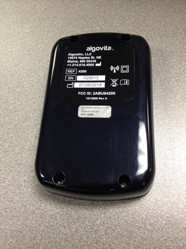
2ABU84200
Jul 23, 20144200
Equipment Class
TNT - Licensed Non-Broadcast Transmitter Worn on Body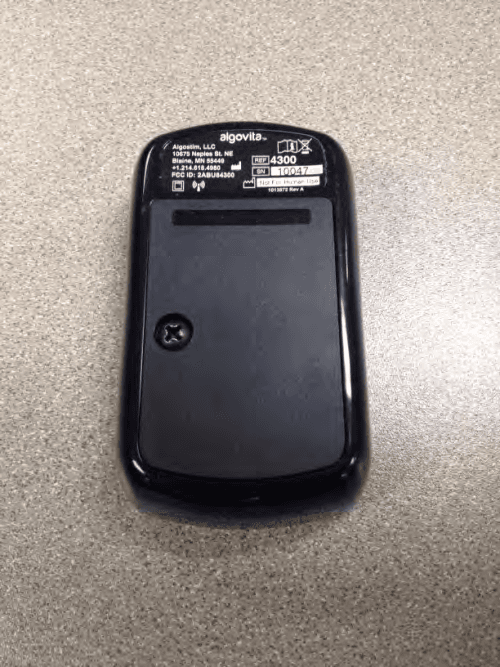
2ABU84300
Jul 23, 20144300
Equipment Class
TNT - Licensed Non-Broadcast Transmitter Worn on Body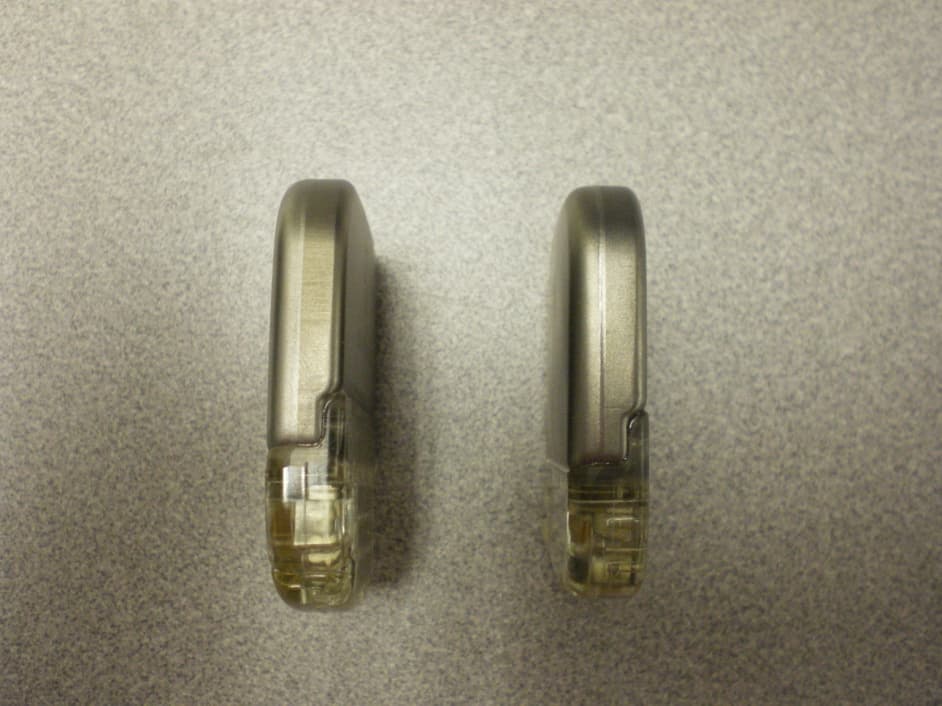
2ABU824082412
Apr 09, 20142408, 2412
Equipment Class
TNT - Licensed Non-Broadcast Transmitter Worn on Body