FCCID.CO- FCC ID Database
HomeCompaniesEquipment ClassesSearch

© 2026 FCC ID Database. All rights reserved.

AboutContactData sourced from FCC public records
  1. Home/
  2. Diamond Kinetics, Inc./
  3. 2ABWR-DKST01

2ABWR-DKST01Diamond Kinetics SwingTracker

Diamond Kinetics, Inc.
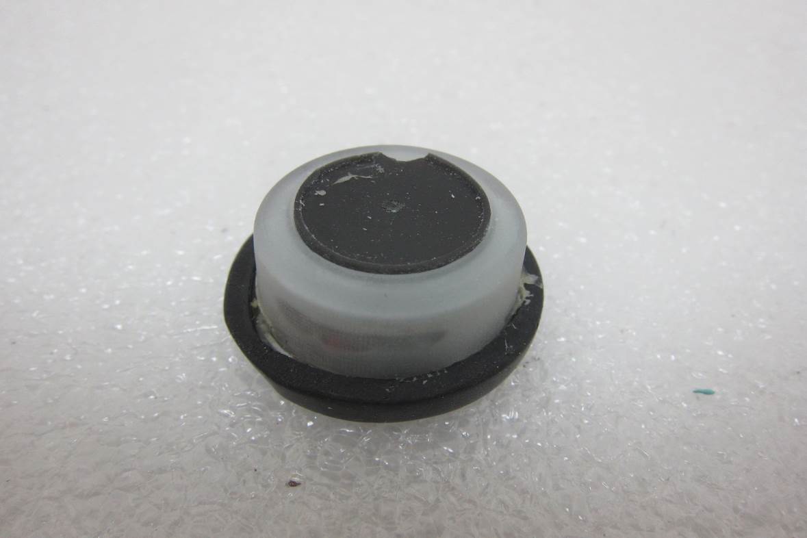
Diamond Kinetics SwingTracker - FCC ID 2ABWR-DKST01 - Diamond Kinetics, Inc.
Click to zoom

Application Details

Equipment Class
DSS - Part 15 Spread Spectrum Transmitter
Date of Grant
Oct 07, 2014
Application Purpose
Original Equipment
Date of Application
Oct 06, 2014
Equipment Note
Diamond Kinetics SwingTracker
Frequency Range
2402.00000000 - 2480.00000000
Company
Diamond Kinetics, Inc.
Country
United States

Documents & Files

Select a file to view

Users Manual

↗

Cover Letter(s)

↗
↗

External Photos

↗

ID Label/Location Info

↗

Internal Photos

↗

RF Exposure Info

↗

Test Report

↗

Test Setup Photos

↗

Document Text

Text extracted from the exhibit documents filed with the FCC. Open a document above to read the original.

Users Manual

1 August 2014 User Guide 2 August 2014 User Guide Important Safety and Handling 3 Getting Started 4 What comes in the box 4 Charging your Sensor 4 Mobile device requirements 4 Downloading the mobile app 7 Turning on and off your Sensor 5 Pairing your Sensor 5 Using your Diamond Kinetics Sensor 5 Attaching your sensor to your bat 4 Initial calibration of your sensor 5 Capturing swings 5 Battery and power management 5 Wet environments 8 Temperature sensitivity and storage 8 Diamond Kinetics Swing Measures 7 Support 9 Customer Support Return policy and warranty Technical specifications 9 9 9 Certification and Compliance 10 3 August 2014 IMPORTANT PLEASE READ CAREFULLY BEFORE USING YOUR DIAMOND KINETICS® SENSOR This User Guide contains important safety, handling and warranty information, as well software license information for your Diamond Kinetics Sensor. Please read carefully before using your Sensor. Failure to follow these safety instructions could result in fire, electric shock or other personal injury and/or damage to your Diamond Kinetics Sensor or other property. ● When you perform a repetitive activity, such as swinging a bat, you may experience occasional discomfort or fatigue. Consult a physician if issues persist. ● Your Diamond Kinetics Sensor contains sensitive electronic components. Do not attempt to modify or repair your Diamond Kinetics Sensor yourself. Disassembling your Sensor with void the manufacturer’s warranty. ● The Diamond Kinetics Sensor contains small parts and is a choking hazards and is not appropriate for children under 3. ● Your Diamond Kinetics Sensor is splash proof. Do not use your sensor in rain or submerge under water. ● Do not overstretch the sensor strap. It is only intended for use with the Diamond Kinetics sensor. ● Unplug the USB power cable and discontinue use if it has become damaged or has been exposed to rain, liquid or excessive moisture 4 August 2014 GETTING STARTED What comes in the Box Sensor Sensor Strap USB Charging Cable Protective Storage Pouch Works with the Free Diamond Kinetics Mobile App USING YOUR DIAMOND KINETICS SENSOR Attaching your Sensor to your Bat Place the end of your bat on a firm surface with the knob pointing upward. Stretch the round hole in the center of the sensor strap over the knob. Position the sensor, with the soft rubber side downward, on top of the bat knob. Hold the sensor in place with your finger. Pull each of the three strap ends over the top of the sensor so that the top of the sensor should remain completely free of the strap. Confirm that the sensor is firmly secured. Your Diamond Kinetics sensor should be attached to your bat on the knob end only using a Diamond Kinetics strap. Do not use any other mechanism to attach your sensor to you bat; doing so will void the manufacturer’s warranty. Turning On and Off your Sensor 5 August 2014 To turn your sensor on, press the button with the “DK” logo on the top of the Sensor. The green indicator light on the top of the sensor will turn on. To turn off, press the button. The green indicator light will turn off. Pairing your Diamond Kinetics Sensor You will need to pair the Diamond Kinetics Sensor to your iOS device to collect data. ● Go to Settings > Bluetooth ● Enable Bluetooth in the Settings Menu, if it is not already on. ● Select the "SwingTracker” sensor. If you do not see SwingTracker in the device list ● Confirm that the sensor is charged. If it is not, see “Charging your Sensor” ● Check that it is not connected to another nearby iOS device. ● Confirm SwingTracker is close to the iOS device and try again. Charging your Sensor Turn off the Sensor. Hold the sensor upright and logo facing up. Rotate the top grey section of the sensor counterclockwise to reveal the charging port on the bottom of the sensor. You will feel the bottom of the sensor “unlock” as you begin to rotate the bottom. Insert the small end of the USB charging cable provided into the exposed charging port on the sensor. The status indicator will begin to flash red. The status indicator will emit a solid red light when charging is complete, taking approximately 3 hours. Remove the charging cable from the computer and sensor. Rotate the top grey section of the sensor clockwise to cover the charging port. You will feel the bottom green section of the sensor lock into place. Never force a charge cable into a USB port of your Diamond Kinetics sensor. If the charge contact does not easily fit into the USB port, confirm that they are properly aligned before attempting to insert again. ONLY use the USB charging cable provided to charge your Diamond Kinetics sensor. Diamond Kinetics is not responsible for the operation of third-party accessories. Initial Calibration of your Sensor 6 August 2014 You can calibrate your sensor at any time, once you have initiated a session. To do so, Select Calibrate on the top left side of the app. Set your bat on the plate so that it matches the illustration. Stand at a normal distance from the plate and align your back foot to be even with the middle point on the plate. Select Start Calibration on the bottom right of the app. You will need to complete the initial sensor calibration within 8 seconds. Capturing Swings Get to your natural load point. Do not move the bat excessively when capturing swings. Battery Life and Power Turning Sensor On: Press the DK logo on the top of the sensor to turn it on. You will see a green light Flash rapidly if not paired. Flash slowly Determine Battery Charge: A battery indicator is listed at the the top of the screen when you are paired with the app and collected session data ; It will alert you when the battery is low. Sleep Mode: The sensor will go into sleep mode and the light will stop blinking if you have not used it for seconds. It will automatically wake up and the green power light turn once the sensor is picked up. Turning Sensor Off: Press and hold the button on the top of the sensor to turn it off. The battery will last up to…

Text truncated - open the document above for the full version.

Cover Letter(s)

SCS-F18: Project and Product Certification Representative Authorization Letter Page 1 of 2 775 Montague Expressway Milpitas, CA 95035 Tel: 408-526-1188 Fax: 408-526-1088 Email: [email protected] Project and Product Certification Representative Authorization Letter Revision History Reason for Amendment (current / obsolete) FromTo Approved Date Initial Release SCS-F18: Project and Product Certification Representative Authorization Letter Page 2 of 2 2014/9/30 To: SIEMIC, Inc. 775 Montague Expressway, Milpitas, CA 95035 USA Dear Sir/Madam, Re: Project and Product Certification Representative Authorization Letter We, Diamond Kinetics, Inc. hereby authorize SIEMIC, Inc. to act as Certification Body for certifying for the following project(s): Product description: Diamond Kinetics SwingTracker Type designation: DKST01 FCC ID:2ABWR-DKST01 We affirm that between SIEMIC, Inc. and International Standards Laboratory, any difference in understanding, including test plan, measurement methods, applicable standards and relevant procedures and processes have been resolved prior to commencement of testing activities. Sincerely, Client’s signature C.J. Handron / CEO Diamond Kinetics, Inc. Address: 700 River Avenue Suite 540, Pittsburgh, Pennsylvania, United States

Cover Letter(s)

SCS-F19: Confidentiality Request Letter Page 1 of 2 775 Montague Expressway Milpitas, CA 95035 Tel: 408-526-1188 Fax: 408-526-1088 Email: [email protected] Confidentiality Request Letter Revision History Reason for Amendment (current / obsolete) FromTo Approved Date Initial Release SCS-F19: Confidentiality Request Letter Page 2 of 2 2014/09/30 To: Federal Communications Commission Authorization and Evaluation Division 7435 Oakland Mills Road Columbia, MD Subject: Permanent Confidentiality Request for FCC ID: 2ABWR-DKST01 We hereby request confidential treatment of information accompanying this application as outlined below: -e.g. Block Diagram -e.g. Schematics -e.g. Operational Description The above materials contain trade secrets and proprietary information not customarily released to the public. The public disclosure of these materials may be harmful to the applicant and provide unjustified benefits to its competitors. The applicant understands that pursuant to Section 0.457 & 0.459 of the Rules, disclosure of this application and all accompanying documentation will not be made before the date of the Grant for this application. Sincerely, Client’s signature : C.J. Handron / CEO Diamond Kinetics, Inc. Address: 700 River Avenue Suite 540, Pittsburgh, Pennsylvania, United States

External Photos

FCC ID: 2ABWR-DKST01 IC: 12312A-DKST01 International Standards Laboratory Report Number: ISL-14LR226FC EXTERNAL PHOTOGRPHS OF EUT FCC ID: 2ABWR-DKST01 IC: 12312A-DKST01 International Standards Laboratory Report Number: ISL-14LR226FC EUT 1 EUT 2 FCC ID: 2ABWR-DKST01 IC: 12312A-DKST01 International Standards Laboratory Report Number: ISL-14LR226FC EUT 3

ID Label/Location Info

FCC ID LABEL FORMAT AND LOCATION Applicant: Diamond Kinetics, Inc. FCC ID: 2ABWR-DKST01 IC: 12312A-DKST01

Internal Photos

FCC ID: 2ABWR-DKST01 IC: 12312A-DKST01 International Standards Laboratory Report Number: ISL-14LR226FC INTERNAL PHOTOGRPHS OF EUT FCC ID: 2ABWR-DKST01 IC: 12312A-DKST01 International Standards Laboratory Report Number: ISL-14LR226FC EUT 1 EUT 2 BT Antenna FCC ID: 2ABWR-DKST01 IC: 12312A-DKST01 International Standards Laboratory Report Number: ISL-14LR226FC EUT 3

RF Exposure Info

-1 of 2- FCC ID: 2ABWR-DKST01 IC: 12312A-DKST01 International Standards Laboratory Report Number: ISL-14LR226FC 1. RF EXPOSURE 1.1. Standard Applicable According to§2.1093 this is a Portable device. For The radiation source included into the device the output power is taken from a corresponding RF test report. If needed the output power is converted to source based, time – average out power. Finally the output power is compared to FCC and IC low power SAR evaluation exemption level. FCC SAR test exclusion: According to KDB 447498 D01 General RF Exposure Guidance v05r02, Appendix A requirement, “The equation and threshold in section 4.3.1 must be applied to determine SAR test exclusion.” 4.3.1. Standalone SAR test exclusion considerations Unless specifically required by the published RF exposure KDB procedures, standalone 1-g head or body and 10-g extremity SAR evaluation for general population exposure conditions, by measurement or numerical simulation, is not required when the corresponding SAR Test Exclusion Threshold condition, listed below, is satisfied. These test exclusion conditions are based on source-based time-averaged maximum conducted output power of the RF channel requiring evaluation, adjusted for tune-up tolerance, and the minimum test separation distance required for the exposure conditions.23 The minimum test separation distance is determined by the smallest distance from the antenna and radiating structures or outer surface of the device, according to the host form factor, exposure conditions and platform requirements, to any part of the body or extremity of a user or bystander (see 5) of section 4.1). To qualify for SAR test exclusion, the test separation distances applied must be fully explained and justified by the operating configurations and exposure conditions of the transmitter and applicable host platform requirements, typically in the SAR measurement or SAR analysis report, according to the required published RF exposure KDB procedures. When no other RF exposure testing or reporting is required, a statement of justification and compliance must be included in the equipment approval, in lieu of the SAR report, to qualify for the SAR test exclusion. When required, the device specific conditions described in the other published RF exposure KDB procedures must be satisfied before applying these SAR test exclusion provisions; for example, handheld PTT two-way radios, handsets, laptops & tablets etc.24 1) The 1-g and 10-g SAR test exclusion thresholds for 100 MHz to 6 GHz at test separation distances ≤ 50 mm are determined by: -2 of 2- FCC ID: 2ABWR-DKST01 IC: 12312A-DKST01 International Standards Laboratory Report Number: ISL-14LR226FC [(max. power of channel, including tune-up tolerance, mW)/(min. test separation distance, mm)] · [√f(GHz)] ≤ 3.0 for 1-g SAR and ≤ 7.5 for 10-g extremity SAR,25 where • f(GHz) is the RF channel transmit frequency in GHz • Power and distance are rounded to the nearest mW and mm before calculation26 • The result is rounded to one decimal place for comparison • 3.0 and 7.5 are referred to as the numeric thresholds in the step 2 below The test exclusions are applicable only when the minimum test separation distance is ≤ 50 mm and for transmission frequencies between 100 MHz and 6 GHz. When the minimum test separation distance is < 5 mm, a distance of 5 mm according to 5) in section 4.1 is applied to determine SAR test exclusion. IC Exemption from Routine Evaluation Limits – SAR Evaluation: RSS 102 Issue 4 SAR evaluation is required if the separation distance between the user and the radiating element of the device is less than or equal to 20 cm, except when the device operates as follows: above 2.2 GHz and up to 3 GHz inclusively, and with output power (i.e. the higher of the conducted or radiated (e.i.r.p.) source-based, time-averaged output power) that is less than or equal to 20 mW for general public use and 100 mW for controlled use; 1.2. Measurement Result: FCC: Frequency (MHz) Max power (dBm) tune- up tolerance(dB) Max power (mW) Min Distance (mm) Result Limit (3.0 @ 1g SAR) 2402-3.7820.6637435.000.2057393.0 2440-7.7820.2642415.000.0825513.0 2480-4.8020.5248075.000.1652943.0 Max Power(mW) =10^((Max Power(dBm) + Tune-up tolerance(dB) )/10) Result = Max Power (mW) / min. distance(mm) * √f(GHz) IC: The Measured Max. conducted output power is -3.78dBm (0.419 mW), e.i.r.p. output power is -3.28dBm (0.47 mW), which is lower than the threshold power level 20mW in RSS 102 issue 4. The SAR measurement is not necessary.

Test Report

Page: 1 of 67 TEST REPORT of FCC Part 15 Subpart C AND CANADA RSS-210 New Application; Class I PC; Class II PC Product : Diamond Kinetics SwingTracker Brand: Diamond Kinetics Model: DKST01 Model Difference: N/A FCC ID: IC: 2ABWR-DKST01 12312A-DKST01 FCC Rule Part: IC Rule Part: §15.247, Cat: DSS RSS-210 issue 8:2010, Annex 8 Applicant: Diamond Kinetics, Inc. Address: 700 River Avenue Suite 318, Pittsburgh, Pennsylvania, United States Test Performed by: International Standards Laboratory <Lung-Tan LAB> *Site Registration No. BSMI: SL2-IN-E-0013; MRA TW1036; TAF: 0997; IC: IC4067B-3; *Address: No. 120, Lane 180, San Ho Tsuen, Hsin Ho Rd. Lung-Tan Hsiang, Tao Yuan County 325, Taiwan *Tel : 886-3-407-1718; Fax: 886-3-407-1738 Report No.: ISL-14LR226FC Issue Date : 2014/09/30 Test results given in this report apply only to the specific sample(s) tested and are traceable to na- tional or international standard through calibra- tion of the equipment and evaluating measure- ment uncertainty herein. This report MUST not be used to claim product endorsement by TAF, NVLAP or any agency of the Government. This test report shall not be reproduced except in full, without the written approval of International Standards Laboratory. -2 of 67- FCC ID: 2ABWR-DKST01 IC: 12312A-DKST01 International Standards Laboratory Report Number: ISL-14LR226FC VERIFICATION OF COMPLIANCE Applicant: Diamond Kinetics, Inc. Product Description: Diamond Kinetics SwingTracker Brand Name: Diamond Kinetics Model No.: DKST01 Model Difference: N/A FCC ID: 2ABWR-DKST01 IC: 12312A-DKST01 Date of test: 2014/09/22 ~ 2014/09/30 Date of EUT Received: 2014/09/22 We hereby certify that: All the tests in this report have been performed and recorded in accordance with the standards de- scribed above and performed by an independent electromagnetic compatibility consultant, Interna- tional Standards Laboratory. The test results contained in this report accurately represent the measurements of the characteristics and the energy generated by sample equipment under test at the time of the test. The sample equip- ment tested as described in this report is in compliance with the limits of above standards. Test By: Date: 2014/09/30 Dion Chang / Engineer Prepared By: Date: 2014/09/30 Eva Kao / Technical Supervisor Approved By: Date: 2014/09/30 Vincent Su / Technical Manager -3 of 67- FCC ID: 2ABWR-DKST01 IC: 12312A-DKST01 International Standards Laboratory Report Number: ISL-14LR226FC Version Version No. Date Description 00 2014/09/30 Initial creation of document -4 of 67- FCC ID: 2ABWR-DKST01 IC: 12312A-DKST01 International Standards Laboratory Report Number: ISL-14LR226FC Table of Contents 1. GENERAL INFORMATION .................................................................................................... 6 1.1. Product Description ....................................................................................................................... 6 1.2. Related Submittal(s) / Grant (s) ..................................................................................................... 7 1.3. Test Methodology .......................................................................................................................... 7 1.4. Test Facility .................................................................................................................................... 7 1.5. Special Accessories ........................................................................................................................ 7 1.6. Equipment Modifications ............................................................................................................... 7 2. SYSTEM TEST CONFIGURATION ....................................................................................... 8 2.1. EUT Configuration ........................................................................................................................ 8 2.2. EUT Exercise ................................................................................................................................. 8 2.3. Test Procedure ................................................................................................................................ 8 2.4. Configuration of Tested System ..................................................................................................... 9 3. SUMMARY OF TEST RESULTS .......................................................................................... 10 4. DESCRIPTION OF TEST MODES ....................................................................................... 10 5. AC POWER LINE CONDUCTED EMISSION TEST ......................................................... 11 5.1. Standard Applicable: .................................................................................................................... 11 5.2. Measurement Equipment Used: ................................................................................................... 11 5.3. EUT Setup: ................................................................................................................................... 11 5.4. Measurement Procedure: ............................................................................................................. 12 5.5. Measurement Result: ................................................................................................................... 12 6. PEAK OUTPUT POWER MEASUREMENT ....................................................................... 15 6.1. Standard Applicable: .................................................................................................................... 15 6.2. Measurement Equipment Used: ................................................................................................... 15 6.3. .Test Set-up: ................................................................................................................................. 16 6.4. M…

Text truncated - open the document above for the full version.

Test Setup Photos

FCC ID: 2ABWR-DKST01 IC: 12312A-DKST01 International Standards Laboratory Report Number: ISL-14LR226FC PHOTOGRAPHS OF SETUP FCC ID: 2ABWR-DKST01 IC: 12312A-DKST01 International Standards Laboratory Report Number: ISL-14LR226FC Radiated Emission Setup Photos FCC ID: 2ABWR-DKST01 IC: 12312A-DKST01 International Standards Laboratory Report Number: ISL-14LR226FC FCC ID: 2ABWR-DKST01 IC: 12312A-DKST01 International Standards Laboratory Report Number: ISL-14LR226FC Conducted Emission Set up Photo

Contact Information

Applicant

C.J. Handron(CEO)
[email protected]4122235341Fax: 4122235241

Test Firm

International Standards Laboratory Corp.Benson Chen
[email protected]886-3-263-8888Fax: 886-3-263-8899

Technical Specifications

#Rule PartsFrequency RangePower Output
115C2.40 GHz - 2.48 GHz400.00 µW
Confidentiality
Long Term
Grant Notes
Output power is conducted.

Other Applications from Diamond Kinetics, Inc.

Bluetooth Low Energy Module - FCC ID 2ABWR-DKT003 - Diamond Kinetics, Inc.
2ABWR-DKT003

Bluetooth Low Energy Module

Jul 21, 2020

Equipment Class

DTS - Digital Transmission System