2ABXDQBE710Bluetooth Earphone
ICON Q CORPORATION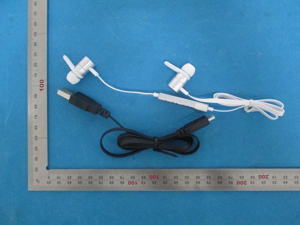
Click to zoom
Application Details
- Equipment Class
- DTS - Digital Transmission System
- Date of Grant
- Jul 14, 2014
- Application Purpose
- Original Equipment
- Date of Application
- Jul 14, 2014
- Equipment Note
- Bluetooth Earphone
- Frequency Range
- 2402.00000000 - 2480.00000000
- Company
- ICON Q CORPORATION
- Country
- United States
Documents & Files
Document Text
Text extracted from the exhibit documents filed with the FCC. Open a document above to read the original.
Users Manual
QBE710 You can end the call you are answering with the ways as follows: Bluetooth Earphone User Manual Specifications The Headset Status Note: The two Phones mentioned follows will be called Phone A and B. Bluetooth headset should be used with the compatible devices which support Bluetooth wireless technology. This allows you to make two calls and enjoy the music streaming at any time freely. Please read this user manual carefully before using the headset, and also read your device’s user manual regarding the Bluetooth function, and pay attention to those important safety and maintenance information. Please read this user manual carefully before using the headset, and also read your device’s user manual regarding the Bluetooth function, and pay attention to those important safety and maintenance information. Please keep the headset away from children. In ON MODE (except call state), press and hold MFB for 3 seconds, until you hear “Power off”, the indicator light turns red for 1 second, then the headset will enter into OFF MODE. Press and hold MFB for 2 seconds to reject the call. In PAIRED MODE, press and hold volume V- for 2 seconds, and say the voice tag as soon as you hear the short beep. (Ensure your phone supports voice dialing function, and you have recorded the voice tag into your phone. See the user guide of your phone for instructions.) Pairing Your Headset With A Bluetooth Phone Ending A Call Rejecting A Call Voice Dialing Structure Sketch Two-call Handling Status No. Headset Status Pairing Mode Not Connected Standby Mode Call State Headset’s indicator light status The headset can be searched, the indicator light flashes red and blue alternately. When in a call, the indicator light flashed blue once each 10 seconds. Charging State Shortly press headset MFB once to hold on the current call and answer another call. Shortly press the headset once to transfer the call from one to another. Press and hold the headset MFB for 2 seconds, the speaker sound “du” ; you can end the current talking call and answer the retained call. Note: All the above operations have to respect the precondition that Phone supports Bluetooth hands free profile V1.5 and Phones are running under call holding function from telecom. When a call is coming, you can answer it with the ways as follows: Answering A Call Bluetooth Specification Bluetooth Profiles Supported Support for Audio Decoding Formats Transmission Power Operation Range Frequency Range Battery Charging Voltage Charging Time Playing Music Time* Talk Time * Standby Time * Dimensions(mm) Weight V4.0 HSP , HFP , A2DP , AVRCP SBC,MP3,APTX Class 2 Up to 10 Meters 2.402-2.480GHz Built-in Rechargeable 3.7V/80mAH(2x40mAH) Lithium Battery DC4.75-5.25V About 2 hours Up to 4.5 hours Up to 5 hours Up to 350 hours L45×W10×H7.5 About 17 g *The time mentioned as above may vary due to user's operation mode and device settings. Charging Your Headset Prior to using the headset for the first time, please fully charge the battery. Approximately 2 hours are required to fully charge the headset. 2. 3. 4. 1. The indicator light turns red while being charged, and will turn blue automatically after being fully charged. When the headset is running out of battery, the indicator light will flash red (the headset will switch off automatically when the battery is drained). Please charge the headset as above steps in time to prolong the battery's useful life (Charging indication will be delayed for a few minutes if the headset has not been used for a long time or the battery is drained). Check the charging device is suit to the headset. Use only the supplied charger to charge the headset, or obey the validation for this product or the maintenance article and could be dangerous. Do not attempt to force open the built-in battery as this could damage the headset. If left unused, a fully charged headset will loose its power automatically. It is recommended to charge the headset each three months. Do not leave the headset in a too hot or too cold condition (best between -10 and 50) which may affect the headset's operations although it is fully charged. Do not dispose of the headset into a fire or water. Note 1: Note 2: Note 3: Note 4: Note 5: Note 6: Turning On The Headset Turning Off The Headset Ensure the headset is off, and the distance between your headset and phone is within 1 meter to activate the Bluetooth function on the phone. Press and hold MFB until the indicator light flashes blue and red alternately and could hear “pairing” as PAIRING MODE. Search Bluetooth devices (see the user guide of your phone for instructions). phone. After waiting for a few seconds, could hear “paired”, then could hear “your phone is connected”.(If the pairing cannot be completed within 5 minutes after the PAIRING MODE has been activated, the headset will enter into the STANDBY MODE. Please repeat above steps to do the pairing again). Ensure the distance between your headset and phone is within effective distance, you can use the headset freely. When the headset is off, it will connect the paired phone automatically if you turn on the headset again within operation range. 1. 2. 3. 4. 5. 6. 7. 1. 2. 3. 1 2 3 4 5 When you are answering one call, there is another call coming: (1)Volume Key+(V+) (2)Speaker (3)Volume Key- (V-) (4)Multifunction Button (MFB) (5)Indicator light (6)Microphone (7)Micro USB Charging Socket (8)NFC Sensor Area Adjusting The Volume Mute During a call, press and hold “V+” for 3 seconds, you could hear “dudu” voice prompt, the headset will enter in to MUTE MODE. In MUTE MODE, the speaker will sound “dudu” twice each 10 seconds, press and hold “V+” for 3 seconds again, you could hear “dudu” voice prompt, then could cancel the MUTE MODE. 1 3 5 6 7 4 2 In OFF MODE, press and hold MFB for 3 seconds, until you hear “Power on”, the indicator light turns blue for 1 second, then the headset will enter into ON MODE. Headset isn’t connected with any devices within 20 minutes, it will au…
Text truncated - open the document above for the full version.
Cover Letter(s)
Jul.07, 2014 Federal Communication Commission Authorization and Evaluation Division FCC ID: 2ABXDQBE710 Re: Confidentiality Request Pursuant to Sections 0.457 and 0.459 of the Commission’s Rules, the applicant hereby requests confidential treatment of information applied this application as outlined below: 1: Block Diagram 2: Circuit Diagram 3: Parts List 4.Operational Description The above materials co ntain trade secrets and proprietary information not customarily released to the public. The public disclosure of these matte rs might be harmful to th e applicant and provide unjustified benefits to its competitors. The Applicant understands that pursuant to Rules 0.457, disclosure of this Application and all accompanying documentation will not be made before the date of the Grant for this application. Sincerely, ICON Q CORPORATION Contact person: Ray Lee Title: Manager
External Photos
External Photos ALL VIEW OF EUT TOP VIEW OF EUT BOTTOM VIEW OF EUT FRONT VIEW OF EUT BACK VIEW OF EUT LEFT VIEW OF EUT RIGHT VIEW OF EUT FRONT VIEW OF EUT (BUTTONS)
ID Label/Location Info
FCC ID Label Location FCC ID: 2ABXDQBE710
Internal Photos
Internal Photos OPEN VIEW OF EUT-1 OPEN VIEW OF EUT-2 OPEN VIEW OF EUT-3 OPEN VIEW OF EUT-4 Battery INTERNAL VIEW OF EUT-1 INTERNAL VIEW OF EUT-2 INTERNAL VIEW OF EUT-3 INTERNAL VIEW OF EUT-4 BT Antenna INTERNAL VIEW OF EUT-5
Test Report
Report No.: AGC01864140601FE08 Page 1 of 52 FCC Test Report Report No.: AGC01864140601FE08 FCC ID : 2ABXDQBE710 APPLICATION PURPOSE : Original Equipment PRODUCT DESIGNATION : Bluetooth Earphone BRAND NAME : ICON Q MODEL NAME : QBE710 CLIENT : ICON Q CORPORATION DATE OF ISSUE : Jul.07, 2014 STANDARD(S) : FCC Part 15 Rules REPORT VERSION : V1.0 Attestation of Global Compliance (Shenzhen) Co., Ltd CAUTION: This report shall not be reproduced except in full without the written permission of the test laboratory and shall not be quoted out of context. Report No.: AGC01864140601FE08 Page 2 of 52 Report Revise Record Report Version Revise Time Issued Date Valid VersionNotes V1.0 / Jul.07, 2014 Valid Original Report Report No.: AGC01864140601FE08 Page 3 of 52 TABLE OF CONTENTS 1. VERIFICATION OF COMPLIANCE......................................................................................................... 5 2.GENERAL INFORMATION ...................................................................................................................... 6 2.1PRODUCT DESCRIPTION ............................................................................................................... 6 2.2 RELATED SUBMITTAL(S)/GRANT(S) ............................................................................................. 6 2.3TEST METHODOLOGY .................................................................................................................... 6 2.4 TEST FACILITY ................................................................................................................................ 6 2.5 SPECIAL ACCESSORIES ................................................................................................................ 6 2.6 EQUIPMENT MODIFICATIONS ....................................................................................................... 7 2.7 MEASUREMENT UNCERTAINTY ................................................................................................... 7 3. SYSTEM TEST CONFIGURATION ......................................................................................................... 8 3.1 CONFIGURATION OF TESTED SYSTEM ....................................................................................... 8 3.2 EQUIPMENT USED IN TESTED SYSTEM ...................................................................................... 8 3.3. SUMMARY OF TEST RESULTS ..................................................................................................... 8 4. DESCRIPTION OF TEST MODES .......................................................................................................... 9 5. ANTENNA REQUIREMENT .................................................................................................................... 9 5.1. STANDARD APPLICABLE .............................................................................................................. 9 5.2. TEST RESULT ................................................................................................................................ 9 6. TEST FACILITY ..................................................................................................................................... 10 7. RADIATED EMISSION .......................................................................................................................... 11 7.1 MEASUREMENT PROCEDURE .................................................................................................... 11 7.2 TEST SETUP .................................................................................................................................. 12 7.3 LIMITS AND MEASUREMENT RESULT ........................................................................................ 13 7.4 TEST RESULT (WORST MODULATION: GFSK) ................................................................................ 13 8. BAND EDGE EMISSION ....................................................................................................................... 26 8.1. MEASUREMENT PROCEDURE ................................................................................................... 26 8.2. TEST SET-UP ............................................................................................................................... 26 8.3. TEST RESULT .............................................................................................................................. 27 9. 6DB BANDWIDTH ................................................................................................................................ 31 9.1. TEST PROCEDURE ...................................................................................................................... 31 9.2. SUMMARY OF TEST RESULTS/PLOTS ...................................................................................... 31 10. CONDUCTED OUTPUT POWER ....................................................................................................... 33 10.1. MEASUREMENT PROCEDURE ................................................................................................. 33 10.2. TEST SET-UP (BLOCK DIAGRAM OF CONFIGURATION) ........................................................ 33 10.3. LIMITS AND MEASUREMENT RESULT ..................................................................................... 34 11. MAXIMUM CONDUCTED OUTPUT POWER SPECTRAL DENSITY ................................................ 36 11.1 MEASUREMENT PROCEDURE .................................................................................................. 36 Report No.: AGC01864140601FE08 Page 4 of 52 11.2 TEST SET-UP (BLOCK DIAGRAM OF CONFIGURATION) ......................................................... 36 11.3 LIMITS AND MEASUREMENT RESULT ...................................................................................... 36 12. FCC LINE CONDUCTED EMISSION TEST ...............................…
Text truncated - open the document above for the full version.
Test Setup Photos
APPENDIX IV PHOTOGRAPHS OF TEST SETUP FCC LINE CONDUCTED EMISSION TEST SETUP FCC RADIATED EMISSION TEST SETUP
Contact Information
Applicant
Ray Lee
Test Firm
Attestation of Global Compliance Shenzhen Co. Ltd.Forrest Lei
Technical Specifications
| # | Rule Parts | Frequency Range | Power Output |
|---|---|---|---|
| 1 | 15C | 2.40 GHz - 2.48 GHz | 2.50 mW |
Other Applications from ICON Q CORPORATION
2ABXDQBS630-BOU
Jul 22, 2014Bluetooth Speaker
Equipment Class
DSS - Part 15 Spread Spectrum Transmitter
2ABXDQBS620-BOU
Mar 09, 2014Bluetooth speaker
Equipment Class
DSS - Part 15 Spread Spectrum Transmitter