2AC2O-CHU200SEFTPOS Payment Terminal
Windcave Limited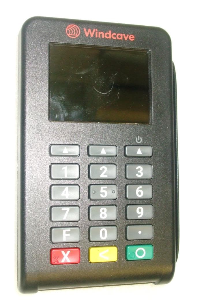
Click to zoom
Application Details
- Equipment Class
- DXX - Part 15 Low Power Communication Device Transmitter
- Date of Grant
- Apr 16, 2024
- Application Purpose
- Original Equipment
- Date of Application
- Apr 16, 2024
- Equipment Note
- EFTPOS Payment Terminal
- Frequency Range
- 13.56000000 - 13.56000000
- Company
- Windcave Limited
- Country
- New Zealand
Documents & Files
Document Text
Text extracted from the exhibit documents filed with the FCC. Open a document above to read the original.
Users Manual
Quick Start Guide - CHU200S Included in the Box • CHU200S Payment Terminal • Cables/Accessories • Quick Start Guide EMV Reader (Insert Here) Magstripe Reader (Swipe Here) Enter Cancel Clear Function Contactless/ NFC Reader ( Ta p H e re) Contact Information Please see https://www.windcave.com/contact for a full list of contact details or use one of the below contact methods: Email: [email protected] New Zealand: 0800-729-6368 Australia: 1-800-006-254 United States: 1-213-378-1190 United Kingdom: 0800-088-6040 The external face of the EFTPOS terminal should be carefully cleaned on a regular basis. This is to ensure that the front plate is free of dirt and solvents which could damage the device or prevent users from using the device as intended. Windcave recommend cleaning the device with a damp cloth or mild soap solution. Do not use any solvents as this may damage the device surface. Do not attempt to open or modify the unit, this will cause the unit to be TAMPERED and render it inoperable. If repairs are required, or the device is no longer needed; the device must be returned to Windcave. Maintenance © 2024 Windcave Limited. All rights reserved. All information in this document is subject to change without notice, and the contents of this document do not constitute an offer or warranty of any kind. Reproduction or publishing this document without Windcave approval is prohibited. This device complies with Industry Canada’s license-exempt RSSs. Operation is subject to the following two conditions: 1. This device may not cause interference; 2. This device must accept any interference, including interference that may cause undesired operation of the device. Le présent appareil est conforme aux CNR d’Industrie Canada applicables aux appareils radio exempts de licence. L’exploitation est autorisée aux deux conditions suivantes: 1. l’appareil ne doit pas produire de brouillage; 2. l’utilisateur de l’appareil doit accepter tout brouillage radioélectrique subi, même si le brouillage est susceptible d’en compromettre le fonctionnement. This device complies with Part 15 of the FCC Rules. Operation is subject to the following two conditions: 1. This device may not cause harmful interference, and 2. This device must accept any interference received, including interference that may cause undesired operation. Changes or modifications not expressly approved by the party responsible for compliance could void the user’s authority to operate the equipment. Note: This equipment has been tested and found to comply with the limits for a Class A digital device, pursuant to part 15 of the FCC Rules. These limits are designed to provide reasonable protection against harmful interference when the equipment is operated in a commercial environment. This equipment generates, uses, and can radiate radio frequency energy and, if not installed and used in accordance with the instruction manual, may cause harmful interference to radio communications. Operation of this equipment in a residential area is likely to cause harmful interference in which case the user will be required to correct the interference at his own expense. IC: 26550-CHU200S FCC ID: 2AC2O-CHU200S
Attestation Statements
Windcave Limited 33 Wilkinson Road, Ellerslie Auckland 1060 New Zealand United States of America Federal Communications Commission Authorization and Evaluation Division 7435 Oakland Mills Road Columbia, MD 21046 Date: 4/10/2024 Ref: Attestation Statements Part 2.911(d)(7) Filing FCC ID: 2AC2O-CHU200S FCC FRN: 0026591925 Windcave Limited (“the applicant”) certifies that, as of the date of the filing of the application, the Windcave Inc office located in Phoenix, Arizona is our designated U.S. agent for service of process for the above referenced FCC ID. Windcave Limited accepts to maintain an agent for no less than one year after the grantee has terminated all marketing and importation or the conclusion of any Commission-related proceeding involving the equipment. The Windcave Inc office located in Phoenix, Arizona accepts, as of the date of the filing of the application, the obligation of the designated U.S. agent for service of process for the above referenced FCC ID. Designated U.S. Agent Information: Name: Windcave Inc FRN: 0033926957 Address: 1601 N 7th Street, Suite 420, Phoenix, AZ 85006 Contact Person: Cameron Collard Tel.: +1 213 378 1190 Email: [email protected] Sincerely, Cameron Collard Global Head of Compliance Risk & PMO Windcave Limited
Attestation Statements
Windcave Limited 33 Wilkinson Road, Ellerslie Auckland 1060 New Zealand United States of America Federal Communications Commission Authorization and Evaluation Division 7435 Oakland Mills Road Columbia, MD 21046 Date: 4/14/2024 SUBJECT: FCC Covered Equipment Attestation for 2AC2O-CHU200S To Whom It May Concern: Windcave Limited certifies that as of the date of the application the equipment for which authorization is sought is not “covered” equipment prohibited from receiving an equipment authorization pursuant to section 2.903 of the FCC rules. Regards, Cameron Collard Global Head of Compliance Risk & PMO Windcave Limited Windcave Limited 33 Wilkinson Road, Ellerslie Auckland 1060 New Zealand United States of America Federal Communications Commission Authorization and Evaluation Division 7435 Oakland Mills Road Columbia, MD 21046 Date: 4/14/2024 SUBJECT: FCC Covered Applicant Attestation To Whom It May Concern: Windcave Limited (“the applicant”) certifies that, as of the date of the filing of the application, the applicant is not identified on the Covered List (as a specifically named entity or any of its subsidiaries or affiliates) as an entity producing “covered” equipment. Regards, Cameron Collard Global Head of Compliance Risk & PMO Windcave Limited
Cover Letter(s)
Windcave Limited 33 Wilkinson Road, Ellerslie Auckland 1060 New Zealand 14 April 2024 Federal Communications Commission Equipment Authorisation Branch 7435 Oakland Mills Road Columbia, MD21046 United States of America Subject: Confidentiality Request for Exhibits under FCC ID: 2AC2O-CHU200S To Whom It May Concern: Pursuant of Section 0.457 and 0.459 of the Commission’s Rules and KDB 726920 D01 Confidentiality Request Procedures, we hereby request that the exhibits listed below, submitted in support of the certification application for FCC ID: 2AC2O-CHU200S, be withheld permanently from public disclosure: • Schematics • Block Diagram • Operational Description • Internal Photographs The above exhibits, owned solely by Windcave Limited, contain trade secrets and proprietary information which is not routinely available to the public or to our competitors. The public disclosure of these materials may be harmful to the applicant and provide unjustified benefits to its competitors. This device is a PCI PTS approved secure PIN entry terminal. It is permanently disabled and made inoperable if the cover is removed due to active tamper detection circuitry. None of the circuit boards or internal components are accessible without permanently disabling the device which requires the device to be returned to the manufacturer as per PCI requirements. Additionally, components are covered with conformal coating where practical. Windcave Limited 33 Wilkinson Road, Ellerslie Auckland 1060 New Zealand The photos of the circuit boards however display secret information regarding the location of tamper detection circuits which could be used to circumvent them and gain access to the internals of the product without triggering a tamper, and then the device can be bugged in order to steal a user’s banking information. For these reasons we do need the internal photos to be restricted. Confidentiality of the internal photographs is specifically sought because the device could be re- engineered from the photographs. Windcave controls information about and access to the device as follows: • The schematics, internal photographs and the like are only used internally by Windcave or by those 3 rd parties as are required to complete product testing. • User manuals do not include schematics, internal photographs, detailed descriptions of device operation or detailed block diagrams. • To meet strict Payment Card Industry (www.pcisecuritystandards.org) security requirements, the devices include security mechanisms which disable the device if it is opened and prevent the modification of the firmware by the user. • The PCI Security Standards require that all devices are returned to Windcave Ltd. at their end of life. Therefore Section 7.6 of the Windcave Customer Contract states: “Consequences of termination: On the termination of this Agreement, you must immediately: a) return all Windcave Limited Products to Windcave Limited...” The applicant understands that pursuant to Section 0.457 of the Rules, disclosure of this application and all accompanying documentation will not be made before the date of the Grant for this application. Yours sincerely Cameron Collard Global Head of Compliance Risk & PMO Windcave Limited
Cover Letter(s)
Windcave Limited 33 Wilkinson Road, Ellerslie Auckland 1060 New Zealand United States of America Federal Communications Commission Authorization and Evaluation Division 7435 Oakland Mills Road Columbia, MD 21046 Date: 4/10/2024 SUBJECT: FCC Application for 2AC2O-CHU200S To Whom It May Concern: We, the undersigned, hereby attest to the fact that we will apply the Declaration of Conformity procedure to the class B computer peripheral portion of this composite filing. Regards, Cameron Collard Global Head of Compliance Risk & PMO Windcave Limited
Cover Letter(s)
Windcave Limited 33 Wilkinson Road, Ellerslie Auckland 1060 New Zealand 27 March 2024 EMC Technologies NZ Ltd 47 Mackelvie Street Grey Lynn Auckland 1021 To Whom It May Concern I hereby authorize Andrew Cutler, General Manager of EMC Technologies NZ Ltd to act on Windcave Ltd behalf with regard to FCC and ISED Certification of the CHU200S Release A device. FCC ID: 2AC2O-CHU200S Contains WiFi/BLE modem FCC ID: XPYNINAW15 ISED ID: 26550-CHU200S ISED HVIN: CHU200S-A-01-00 ISED PMN: CHU200S Release A ISED HMN: n/a ISED FVIN: V1.3.8.8A1 Contains WiFi modem ISED ID: 8595A-NINAW15 Yours Sincerely Cameron Collard Global Head of Compliance Risk & PMO Windcave Limited
External Photos
____________________________________________________________________________________________________________________________________________________________________________ Page 22 of 29 Test Report No 230313.2b 9 th April 2024 This report may not be reproduced except in full. 9. PHOTOGRAPHS Front Face Side Face showing card slot FCC ID: 2AC2O-CHU200S ____________________________________________________________________________________________________________________________________________________________________________ Page 23 of 29 Test Report No 230313.2b 9 th April 2024 This report may not be reproduced except in full. Side Face Back Face FCC ID: 2AC2O-CHU200S ____________________________________________________________________________________________________________________________________________________________________________ Page 24 of 29 Test Report No 230313.2b 9 th April 2024 This report may not be reproduced except in full. Side Face Top Face FCC ID: 2AC2O-CHU200S ____________________________________________________________________________________________________________________________________________________________________________ Page 25 of 29 Test Report No 230313.2b 9 th April 2024 This report may not be reproduced except in full. Charging Port Label FCC ID: 2AC2O-CHU200S
ID Label/Location Info
Page 1 of 1 FCC ID: 2AC2O-CHU200S
RF Exposure Info
© cetecom advanced GmbH Page 1 of 44 TEST REPORT Test Report No.: 1-6209/23-01-02-A-FCC Testing Laboratory Applicant cetecom advanced GmbH Untertuerkheimer Strasse 6 – 10 66117 Saarbruecken/Germany Phone: + 49 681 5 98 - 0 Fax: + 49 681 5 98 - 9075 Internet: https://www.cetecomadvanced.com e-mail: [email protected] Accredited Test Laboratory: The testing laboratory (area of testing) is accredited according to DIN EN ISO/IEC 17025 (2018-03) by the Deutsche Akkreditierungsstelle GmbH (DAkkS) The accreditation is valid for the scope of testing procedures as stated in the accreditation certificate starting with the registration number: D-PL-12047-01-00. Windcave Limited 33 Wilkinson Road 1060 Ellerslie, Auckland/NEW ZEALAND Phone: +64 9 309 4693 Contact: Cameron Collard e-mail: [email protected] Phone: +64 93 09 46 93 Manufacturer Windcave Limited 33 Wilkinson Road 1060 Ellerslie, Auckland/NEW ZEALAND Test Standards IEC/IEEE 62209-1528-2020 Measurement procedure for the assessment of specific absorption rate of human exposure to radio frequency fields from hand-held and body-mounted wireless communication devices – Part 1528: Human models, instrumentation, and procedures (Frequency range of 4 MHz to 10 GHz) RSS-102 Issue 5 Radio Frequency Exposure Compliance of Radiocommunication Apparatus (All Frequency Bands) For further applied test standards please refer to section 3 of this test report. Test Item Kind of test item: handheld payment terminal Device type: portable device Model name: CHU200S S/N serial number: 3523250037 / 3523250083 FCC-ID: 2AC2O-CHU200S Product Marketing Name (PMN): CHU200S Release A Hardware Version Identification No. (HVIN): CHU200S-A-01-00 Hardware status: CHU200S-A-01-00 FVIN: V1.3.8.8A1 Software status: V1.0.2.0 Firmware version: V3.0.0.2 Frequency: see technical details Antenna: integrated antenna Battery option: Integrated battery Test sample status: identical prototype Exposure category: general population / uncontrolled environment This test report is electronically signed and valid without handwritten signature. For verification of the electronic signatures, the public keys can be requested at the testing laboratory. Test Report authorised: Test performed: Alexander Hnatovskiy Marco Scigliano Lab Manager Testing Manager Radio Labs Radio Labs Test report no.: 1-6209/23-01-02-A © cetecom advanced GmbH Page 2 of 44 1 Table of contents 1 Table of contents ............................................................................................................................................ 2 2 General information ....................................................................................................................................... 3 2.1 Notes and disclaimer .......................................................................................................................... 3 2.2 Application details ............................................................................................................................... 3 2.3 Statement of compliance .................................................................................................................... 3 2.4 Technical details .................................................................................................................................. 4 2.5 Transmitter and Antenna Operating Configurations ....................................................................... 4 3 Test standards/ procedures references ....................................................................................................... 5 3.1 RF exposure limits .............................................................................................................................. 6 4 Reporting statements of conformity – decision rule .................................................................................. 7 5 Summary of Measurement Results .............................................................................................................. 7 6 Test Environment ........................................................................................................................................... 8 7 Test Set-up ...................................................................................................................................................... 9 7.1 Measurement system .......................................................................................................................... 9 7.1.1 System Description ..................................................................................................................... 9 7.1.2 Test environment ...................................................................................................................... 10 7.1.3 Probe description ...................................................................................................................... 10 7.1.4 Phantom description ................................................................................................................. 11 7.1.5 Laptop Extension Kit for Device holder .................................................................................... 11 7.1.6 Scanning procedure .................................................................................................................. 12 7.1.7 Comparison of DASY 52 NEO and cDASY6/DASY8 ............................................................... 16 7.1.8 Spatial Peak SAR Evaluation ................................................................................................... 17 7.1.9 Data Storage and Evaluation .................................................................................................... 20 7.1.10 Tissue simulating liquids: dielectric properties ......................................................................... 22 7.1.11 Tissue simulating liquids: parameters ...........................................…
Text truncated - open the document above for the full version.
RF Exposure Info
Page 1 of 50 Annex D Appendix to Test Report No.: 1-6209/23-01-02 Testing Laboratory cetecom advanced GmbH Untertuerkheimer Strasse 6 – 10 66117 Saarbruecken/Germany Phone: + 49 681 5 98 - 0 Fax: + 49 681 5 98 - 9075 Internet: https://www.cetecomadvanced.com e-mail: [email protected] Accredited Test Laboratory: The testing laboratory (area of testing) is accredited according to DIN EN ISO/IEC 17025 (2018-03) by the Deutsche Akkreditierungsstelle GmbH (DAkkS) The accreditation is valid for the scope of testing procedures as stated in the accreditation certificate starting with the registration number: D-PL-12047-01-00. Appendix with Calibration data, Phantom certificate and system check information 2012-01-16 Test report no.: 1-6209/23-01-02 Page 2 of 50 1 Table of contents 1 Table of contents ....................................................................................................................................... 2 2 Calibration report “Probe EX3DV4” – SN: 3944 ..................................................................................... 3 3 Calibration report “Probe EX3DV4” – SN: 7635 ................................................................................... 14 4 Calibration report “13 MHz System validation dipole” ........................................................................ 24 5 Calibration report “2450 MHz System validation dipole” .................................................................... 30 6 Calibration certificate of Data Acquisition Unit (DAE) – SN: 413 ....................................................... 39 7 Calibration certificate of Data Acquisition Unit (DAE) – SN: 477 ....................................................... 40 8 Certificate of “SAM Twin Phantom V4.0, V5.0, V8.0’’ .......................................................................... 41 9 Certificate of “ELI Phantom V8.0’’ ......................................................................................................... 43 10 Application Note System Performance Check .............................................................................. 44 10.1 Purpose of system performance check ................................................................................. 44 10.2 System Performance check procedure .................................................................................. 44 10.3 Uncertainty Budget ................................................................................................................... 45 10.4 Power set-up for validation ...................................................................................................... 49 10.5 Laboratory reflection ................................................................................................................ 50 10.6 Additional system checks ........................................................................................................ 50 Test report no.: 1-6209/23-01-02 Page 3 of 50 2 Calibration report “Probe EX3DV4” – SN: 3944 Test report no.: 1-6209/23-01-02 Page 4 of 50 Test report no.: 1-6209/23-01-02 Page 5 of 50 Test report no.: 1-6209/23-01-02 Page 6 of 50 Test report no.: 1-6209/23-01-02 Page 7 of 50 Test report no.: 1-6209/23-01-02 Page 8 of 50 Test report no.: 1-6209/23-01-02 Page 9 of 50 Test report no.: 1-6209/23-01-02 Page 10 of 50 Test report no.: 1-6209/23-01-02 Page 11 of 50 Test report no.: 1-6209/23-01-02 Page 12 of 50 Test report no.: 1-6209/23-01-02 Page 13 of 50 Test report no.: 1-6209/23-01-02 Page 14 of 50 3 Calibration report “Probe EX3DV4” – SN: 7635 Test report no.: 1-6209/23-01-02 Page 15 of 50 Test report no.: 1-6209/23-01-02 Page 16 of 50 Test report no.: 1-6209/23-01-02 Page 17 of 50 Test report no.: 1-6209/23-01-02 Page 18 of 50 Test report no.: 1-6209/23-01-02 Page 19 of 50 Test report no.: 1-6209/23-01-02 Page 20 of 50 Test report no.: 1-6209/23-01-02 Page 21 of 50 Test report no.: 1-6209/23-01-02 Page 22 of 50 Test report no.: 1-6209/23-01-02 Page 23 of 50 Test report no.: 1-6209/23-01-02 Page 24 of 50 4 Calibration report “13 MHz System validation dipole” Test report no.: 1-6209/23-01-02 Page 25 of 50 Test report no.: 1-6209/23-01-02 Page 26 of 50 Test report no.: 1-6209/23-01-02 Page 27 of 50 Test report no.: 1-6209/23-01-02 Page 28 of 50 Test report no.: 1-6209/23-01-02 Page 29 of 50 Test report no.: 1-6209/23-01-02 Page 30 of 50 5 Calibration report “2450 MHz System validation dipole” Test report no.: 1-6209/23-01-02 Page 31 of 50 Test report no.: 1-6209/23-01-02 Page 32 of 50 Test report no.: 1-6209/23-01-02 Page 33 of 50 Test report no.: 1-6209/23-01-02 Page 34 of 50 Test report no.: 1-6209/23-01-02 Page 35 of 50 Test report no.: 1-6209/23-01-02 Page 36 of 50 Antenna Parameters with Head TSL From cal. data Measured 2023-06-06 Impedance; transformed to feed point 52.8 Ω + 3.7 jΩ 52.4 Ω + 1.1 jΩ Return Loss -26.9 dB -31.7 dB Test report no.: 1-6209/23-01-02 Page 37 of 50 Test report no.: 1-6209/23-01-02 Page 38 of 50 Test report no.: 1-6209/23-01-02 Page 39 of 50 6 Calibration certificate of Data Acquisition Unit (DAE) – SN: 413 Test report no.: 1-6209/23-01-02 Page 40 of 50 7 Calibration certificate of Data Acquisition Unit (DAE) – SN: 477 Test report no.: 1-6209/23-01-02 Page 41 of 50 8 Certificate of “SAM Twin Phantom V4.0, V5.0, V8.0’’ Test report no.: 1-6209/23-01-02 Page 42 of 50 Test report no.: 1-6209/23-01-02 Page 43 of 50 9 Certificate of “ELI Phantom V8.0’’ Test report no.: 1-6209/23-01-02 Page 44 of 50 10 Application Note System Performance Check 10.1 Purpose of system performance check The system performance check verifies that the system operates within its specifications. System and operator errors can be detected and corrected. It is recommended that the system performance check is performed prior to any usage of the system in order to guarantee reproducible results. The measurement of the Specific Absorption Rate (SAR) is a complicated task and the result depends on the pro…
Text truncated - open the document above for the full version.
Test Report
0101 NFC Antenna CHU200S A01 22/03/2024 C:\SVN\Elec\PB0318\PB0318-A01\CHU200S_NFC_Antenna.SchDoc Date: Revision Sheetof Engineer: Reviewer: ME NV This drawing and/or technical information is issued in confidence and may not be reproduced, whole or in part, copied, loaned or used for any other purpose without written permission from Windcave Limited, 33 Wilkinson Road, Auckland 1060, NEW ZEALAND, +64 9 3094693 [No Variations]Assembly Page Size: A4 12345 CN1 FPC EDGE 5 WAY 2-Turn Inductive Coil Antenna for NFC PCB PB0318-A01 PICN101 PICN102 PICN103 PICN104 PICN105 COCN1 COPCB
Test Setup Photos
Accessories FCC ID: 2AC2O-CHU200S Radiated Emissions Test Setup FCC ID: 2AC2O-CHU200S Biconical Antenna pointing towards Test Shed Log Periodic Antenna pointing towards Test Shed FCC ID: 2AC2O-CHU200S Loop Antenna pointing towards Test Shed Horn Antenna pointing towards Test Shed FCC ID: 2AC2O-CHU200S
Test Setup Photos
Page 1 of 7 Annex C Photo documentation Appendix to Test Report No.: 1-6209/23-01-02 Testing Laboratory cetecom advanced GmbH Untertuerkheimer Strasse 6 – 10 66117 Saarbruecken/Germany Phone: + 49 681 5 98 - 0 Fax: + 49 681 5 98 - 9075 Internet: https://www.cetecomadvanced.com e-mail: [email protected] Accredited Test Laboratory: The testing laboratory (area of testing) is accredited according to DIN EN ISO/IEC 17025 (2018-03) by the Deutsche Akkreditierungsstelle GmbH (DAkkS) The accreditation is valid for the scope of testing procedures as stated in the accreditation certificate starting with the registration number: D-PL-12047-01-00. Test report no.: 1-6209/23-01-02 Page 2 of 7 Photo 1: Measurement System DASY Photo 2: DUT - front view Test report no.: 1-6209/23-01-02 Page 3 of 7 Photo 3: DUT - right side view Photo 4: DUT - back side view Test report no.: 1-6209/23-01-02 Page 4 of 7 Photo 5: DUT - back side view (label) Photo 6: Test position front side with 0 mm distance Test report no.: 1-6209/23-01-02 Page 5 of 7 Photo 7: Test position back side with 0 mm distance Photo 8: Test position left side with 0 mm distance Test report no.: 1-6209/23-01-02 Page 6 of 7 Photo 9: Test position right side with 0 mm distance Photo 10: Test position top side with 0 mm distance Test report no.: 1-6209/23-01-02 Page 7 of 7 Photo 11: Test position bottom side with 0 mm distance
Contact Information
Applicant
Cameron Collard
Test Firm
EMC Technologies (NZ) LtdAndrew Cutler
Technical Specifications
| # | Rule Parts | Frequency Range | Power Output |
|---|---|---|---|
| 1 | 15C | 13.56 MHz - 13.56 MHz | - |
Other Applications from Windcave Limited
2AC2O-CHU200TLRC
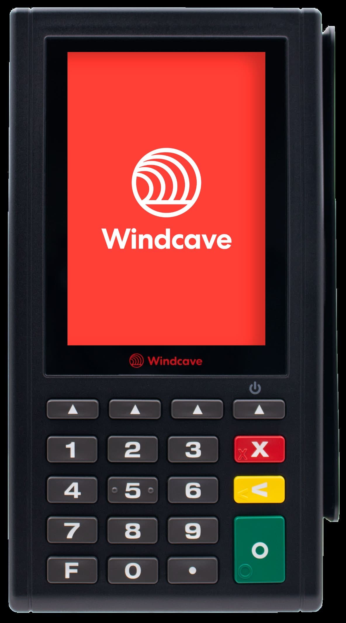
May 04, 2026Integrated Payment Terminal
Equipment Class
DXX - Part 15 Low Power Communication Device Transmitter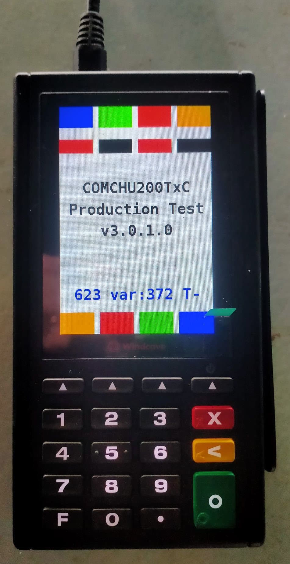
2AC2O-CHU200TRC
Apr 23, 2026Portable Payment Terminal
Equipment Class
DXX - Part 15 Low Power Communication Device Transmitter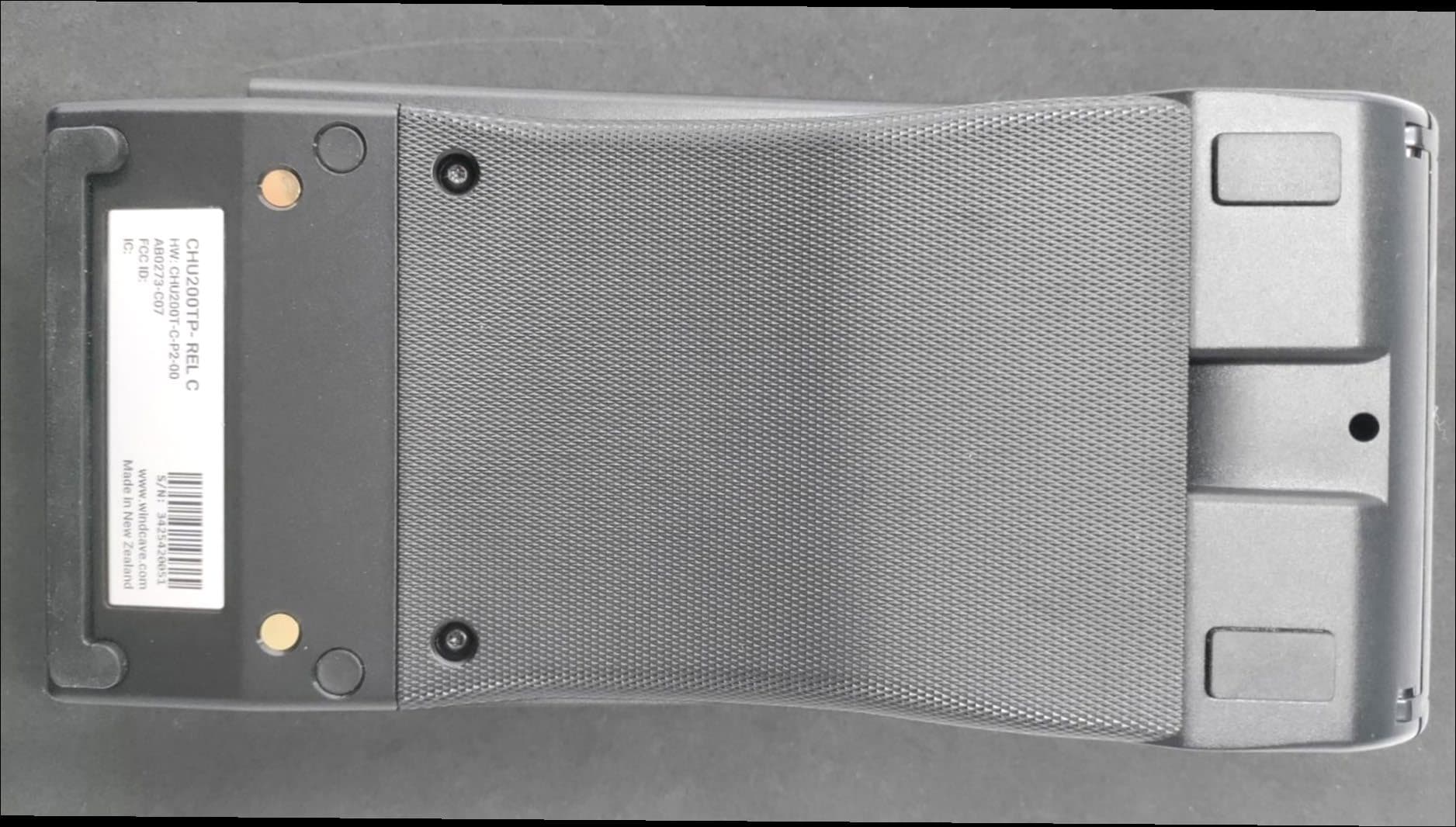
2AC2O-CHU200TPRC
Feb 06, 2026Desktop Payment Terminal
Equipment Class
DXX - Part 15 Low Power Communication Device Transmitter
2AC2O-SCR200MO-B
Apr 28, 2022Contact Secure Card Reader with NFC Transmitter
Equipment Class
DXX - Part 15 Low Power Communication Device Transmitter
2AC2O-CHU200MP
Jan 17, 2021Mobile Secure Payment Terminal with NFC Transmitter
Equipment Class
DXX - Part 15 Low Power Communication Device Transmitter