2AC2Z-VV-106Two Way Radio
Quanzhou Leixen Electronics Co., Ltd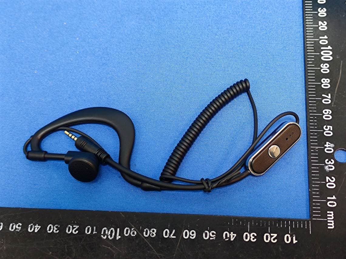
Click to zoom
Application Details
- Equipment Class
- FRF - Part 95 Family Radio Face Held Transmitter
- Date of Grant
- Sep 08, 2025
- Application Purpose
- Original Equipment
- Equipment Note
- Two Way Radio
- Frequency Range
- 462.55000000 - 462.72500000
- Country
- China
Documents & Files
Document Text
Text extracted from the exhibit documents filed with the FCC. Open a document above to read the original.
Users Manual
1 User Manual Any Changes or modifications not expressly approved by the party responsible for compliance could void the user's authority to operate the equipment. This device complies with part 15 of the FCC Rules. Operation is subject to the following two conditions: (1) This device may not cause harmful interference, and (2) this device must accept any interference received, including interference that may cause undesired operation. Note: This equipment has been tested and found to comply with the limits for a Class B digital device, pursuant to part 15 of the FCC Rules. These limits are designed to provide reasonable protection against harmful interference in a residential installation. This equipment generates, uses and can radiate radio frequency energy and, if not installed and used in accordance with the instructions, may cause harmful interference to radio communications. However, there is no guarantee that interference will not occur in a particular installation. If this equipment does cause harmful interference to radio or television reception, which can be determined by turning the equipment off and on, the user is encouraged to try to correct the interference by one or more of the following measures: —Reorient or relocate the receiving antenna. —Increase the separation between the equipment and receiver. —Connect the equipment into an outlet on a circuit different from that to which the receiver is connected. —Consult the dealer or an experienced radio/TV technician for help. Specific Absorption Rate (SAR) information SAR tests are conducted using standard operating positions accepted by the FCC with the device transmitting at its highest certified power level in all tested frequency bands, although the SAR is determined at the highest certified power level, the actual SAR level of the device while operating can be well below the maximum value. Before a new product is a available for sale to the public, it must be tested and certified to the FCC that it does not exceed the exposure limit established by the FCC, tests for each interphone are performed in positions and 2 locations as required by the FCC. For face, this part has been tested and meets the FCC RF exposure guidelines when used with an accessory designated for this product or when used with an accessory that contains no metal. This equipment should be installed and operated with minimum distance 25 mm between the radiator& your face. For body, this equipment complies with FCC radiation exposure limits set forth for an uncontrolled environment . The device is authorized to operate at a duty factor not to exceed 50%. Accessories & Options Welcome to your new radio. Please unpack it carefully and ensure that the below accessories are included. If you find any missing or damaged components, please contact your dealer immediately. Supplied Accessories Item Qty Radio 2 Earphone 2 Charging Cable 2 Lifting Rope 2 User Manual 1 Optional Accessories Programming Cable Charging Adapter Charging When the radio beeps “Di-doo”, and the LED light flash green, please charge the battery of the radio as follow: Put the micro USB plug of the charging cable into the socket of the radio, put the USB connector of the other end of the charging cable to adapter. The adapter must be connected to the 100-240 volt AC mains. The Blue light would flash when the radio is charging. After charging the radio about 1.5 hours, the charging would be completed. 3 The Blue light turns off automatically. Basic Operation Power on/off Poking the switch on the side of the radio to power on/off. Three ascending tones will sound, indicating that the radio has correctly powered on, the channel number will be announced followed. Adjusting Volume Press the key on the radio to increase volume. After reaching the highest level, the volume returns to level 1. The volume can be set to levels 1-4 or 1-8 through the programming software. Select Frequency Press and hold the key to increase channel. Channel number will be announced when channel changed. After reaching the highest channel, the channel returns to channel 1. Transmitting and receiving To transmit, press and hold the PTT key on the microphone of the earphone and speak normally. Release the PTT key to stop transmitting. For best voice quality, hold the microphone about 2 IN (5 cm) away from your mouth and speak normally. Radios can only communicate in the same channel.A red LED indicates that the transmitter is active. A green LED indicates that the radio is receiving signal. 4 Programming Operation User can program the radio through programming software. The connector of programming cable connect to the radio is 2.5 Pin 4 poles. The sequence of the USB and the connect diagram showed as following: Auto Power Off (APO) Auto Power Off will automatically turn the radio off after a set length of inactivity. This function should be programmed through software. The Auto Power Off interval can be set to 10 minutes, 20 minutes, 30 minutes, 40 minutes, 50 minutes, 60 minutes, 90 minutes, 2 hours, 4 hours, 6 hours, 8 hours, 10 hours, 12 hours, 14 hours, or 16 hours. Opening Tone Enable opening tone through software, the radio would beep when radio turn on. Default: ON. Scan Press a key which programmed as Scan, would enable scanning feature. Time out timer(TOT) You may se t a TOT through software to specify a time-out timer for the transmitter. Setting such a timer would prevent accidental, lengthy transmissions where the transmitter does not properly unkey(a stuck PTT key, for instance). Not only could such transmissions be disruptive to other communications, they could damage the transmitter. Default: OFF. 5 Programming software password A password can be set through the programming software to the radio. Once a password programmed to the radio, the radio can only be programmed when the password correct input in the software. Lease Feature When lease feature enabled through programming software, the radio flas…
Text truncated - open the document above for the full version.
External Photos
Bay Area Compliance Laboratories Corp. (Dongguan) EXHIBIT No.: XMDN240327-16017E-RF-EXP Page 1 / 8 EUT EXTERNAL PHOTOS Bay Area Compliance Laboratories Corp. (Dongguan) EXHIBIT No.: XMDN240327-16017E-RF-EXP Page 2 / 8 VV-106 Bay Area Compliance Laboratories Corp. (Dongguan) EXHIBIT No.: XMDN240327-16017E-RF-EXP Page 3 / 8 Bay Area Compliance Laboratories Corp. (Dongguan) EXHIBIT No.: XMDN240327-16017E-RF-EXP Page 4 / 8 Bay Area Compliance Laboratories Corp. (Dongguan) EXHIBIT No.: XMDN240327-16017E-RF-EXP Page 5 / 8 X3 Bay Area Compliance Laboratories Corp. (Dongguan) EXHIBIT No.: XMDN240327-16017E-RF-EXP Page 6 / 8 Bay Area Compliance Laboratories Corp. (Dongguan) EXHIBIT No.: XMDN240327-16017E-RF-EXP Page 7 / 8 Bay Area Compliance Laboratories Corp. (Dongguan) EXHIBIT No.: XMDN240327-16017E-RF-EXP Page 8 / 8 *****END *****
ID Label/Location Info
FCC ID: 2AC2Z-VV-106 Two Way Radio Quanzhou Leixen Electronics Co., Ltd VV-106 S/N: VV106LE001
Internal Photos
Bay Area Compliance Laboratories Corp. (Dongguan) EXHIBIT No.: XMDN240327-16017E-RF-INP Page 1 / 3 EUT INTERNAL PHOTOS Bay Area Compliance Laboratories Corp. (Dongguan) EXHIBIT No.: XMDN240327-16017E-RF-INP Page 2 / 3 Antenna Bay Area Compliance Laboratories Corp. (Dongguan) EXHIBIT No.: XMDN240327-16017E-RF-INP Page 3 / 3 *****END *****
RF Exposure Info
FCC SAR TEST REPORT Applicant: Quanzhou Leixen Electronics Co., Ltd Address: No.48, Jinqiao Road, Changtai Street Quanzhou City China P r o d u c t N a m e : Two Way Radio F C C I D : 2AC2Z-VV-106 Standard(s): 47 CFR Part 2(2.1093) Report Number: XMDN240327-16017E-20 Report Date: 2025/07/31 The above device has been tested and found compliant with the requirement of the relative standards by Bay Area Compliance Laboratories Corp. (Dongguan). Reviewed By: Mark Dong Approved By: Brave Lu Title: SAR Engineer Title: SAR Supervisor Bay Area Compliance Laboratories Corp. (Dongguan) No.12, Pulong East 1 st Road, Tangxia Town, Dongguan, Guangdong, China Tel: +86-769-86858888 Fax: +86-769-86858891 www.baclcorp.com.cn Note: The information marked ▲ is provided by the applicant, the laboratory is not responsible for its authenticity and this information can affect the validity of the result in the test report. Unless otherwise stated the results shown in this test report refer only to the sample(s) tested. This report cannot be reproduced except in full, without prior written approval of the Company. This report is valid only with a valid digital signature. The digital signature may be available only under the Adobe software above version 7.0. This report may contain data that are not covered by the accreditation scope and shall be marked with ★.This report must not be used by the client to claim product certification, approval, or endorsement by NVLAP, NIST, or any agency of the U.S. Government. Each test item follows the test standard(s) without deviation Bay Area Compliance Laboratories Corp. (Dongguan) Report No.: XMDN240327-16017E-20 Report Template Version: FCC SAR-V1.0 2 of 51 SAR TEST RESULTS SUMMARY Mode Max. SAR Level(s) Reported(W/kg) Limit PTT(462.5500-467.7125MHz) 1g Head SAR(Face Up) 0.01 1.6 (W/kg) 1g Body SAR(Body Back) 0.21 Applicable Standards FCC 47 CFR part 2.1093 Radiofrequency radiation exposure evaluation: portable devices IEEE1528:2013 IEEE Recommended Practice for Determining the Peak Spatial-Average Specific Absorption Rate (SAR) in the Human Head from Wireless Communications Devices: Measurement Techniques RF Exposure Procedures: TCB Workshop April 2019 KDB procedures KDB 447498 D01 General RF Exposure Guidance v06 KDB 865664 D01 SAR Measurement 100 MHz to 6 GHz v01r04 KDB 865664 D02 RF Exposure Reporting v01r02 KDB 643646 D01 SAR Test for PTT Radios v01r03 Note: This wireless device has been shown to be capable of compliance for localized specific absorption rate (SAR) for General Population/Uncontrolled Exposure limits specified in FCC 47 CFR part 2.1093 and has been tested in accordance with the measurement procedures specified in IEEE 1528-2013 and RF exposure KDB procedures. The results and statements contained in this report pertain only to the device(s) evaluated. Bay Area Compliance Laboratories Corp. (Dongguan) Report No.: XMDN240327-16017E-20 Report Template Version: FCC SAR-V1.0 3 of 51 TABLE OF CONTENTS DOCUMENT REVISION HISTORY ......................................................................................................................... 4 1.GENERAL INFORMATION .................................................................................................................................... 5 1.1 PRODUCT DESCRIPTION FOR EQUIPMENT UNDER TEST (EUT) .............................................................................. 5 2.REFERENCE, STANDARDS, AND GUIDELINES ............................................................................................... 6 2.1 SAR LIMITS ........................................................................................................................................................... 6 2.2 TEST FACILITY ....................................................................................................................................................... 7 3.DESCRIPTION OF TEST SYSTEM ....................................................................................................................... 8 4. EQUIPMENT LIST AND CALIBRATION ......................................................................................................... 13 4.1 EQUIPMENTS LIST & CALIBRATION INFORMATION .............................................................................................. 13 5. SAR MEASUREMENT SYSTEM VERIFICATION .......................................................................................... 14 5.1 LIQUID VERIFICATION .......................................................................................................................................... 14 5.2 SYSTEM ACCURACY VERIFICATION ..................................................................................................................... 15 5.3 SAR SYSTEM VALIDATION DATA ............................................................................................................... 16 6. EUT TEST STRATEGY AND METHODOLOGY ............................................................................................. 17 6.1 TEST POSITIONS FOR FRONT-OF-FACE CONFIGURATIONS ..................................................................................... 17 6.2 TEST POSITIONS FOR BODY-WORN AND OTHER CONFIGURATIONS ........................................................................ 18 6.3 TEST DISTANCE FOR SAR EVALUATION .............................................................................................................. 18 6.4 SAR EVALUATION PROCEDURE ........................................................................................................................... 19 7. CONDUCTED OUTPUT POWER MEASUREMENT ....................................................................................... 20 7.1 TEST PROCEDURE ................................................................................................................................................ 20 7.2 MAXIMUM TARGET OUTPUT POWER..........…
Text truncated - open the document above for the full version.
RF Exposure Info
Bay Area Compliance Laboratories Corp. (Dongguan) Report No.: XMDN240327-16017E-20 Report Template Version: FCC SAR-V1.0 43 of 51 Bay Area Compliance Laboratories Corp. (Dongguan) Report No.: XMDN240327-16017E-20 Report Template Version: FCC SAR-V1.0 44 of 51 Bay Area Compliance Laboratories Corp. (Dongguan) Report No.: XMDN240327-16017E-20 Report Template Version: FCC SAR-V1.0 45 of 51 Bay Area Compliance Laboratories Corp. (Dongguan) Report No.: XMDN240327-16017E-20 Report Template Version: FCC SAR-V1.0 46 of 51 Bay Area Compliance Laboratories Corp. (Dongguan) Report No.: XMDN240327-16017E-20 Report Template Version: FCC SAR-V1.0 47 of 51 Bay Area Compliance Laboratories Corp. (Dongguan) Report No.: XMDN240327-16017E-20 Report Template Version: FCC SAR-V1.0 48 of 51 APPENDIX E - RETURN LOSS AND IMPEDANCE MEASUREMENT D450V3 - SN:1096 Extended Dipole Calibrations Referring to KDB 865664 D01, if dipoles are verified in return loss(< -20dB, within 20% of prior calibration), and in impedance(within 5 ohm of prior calibration), the annual calibration is not necessary and the calibration interval can be extended. Test Equipment Information: Equipment Model S/N Calibration Date Calibration Due Date Simulated Tissue 450 MHz Head TS-450H 2409045001 Each Time / Oval Flat Phantom ELI V8.0 2051 NCR NCR Network Analyzer E5071C MY46519680 2023/07/16 2024/07/15 Network Analyzer Calibration Kit 50 Ω 51026 NCR NCR Justification of the extended calibration D450V3 - SN:1096 450MHz Head Date of Measurement Return-Loss (dB) Delta (%) Real Impedance (ohm) Delta (ohm) Imaginary Impedance (ohm) Delta (ohm) 2022/11/17 (Cal. Report) -21.97 / 56.076 / -5.8988 / 2023/11/15 (Extended) -21.435 2.44 59.227 -3.151-4.2414 -1.6574 The return loss is <-20dB, within 20% of prior calibration; the impedance is within 5 ohm of prior calibration. Therefore the verification result should support extended calibration. Bay Area Compliance Laboratories Corp. (Dongguan) Report No.: XMDN240327-16017E-20 Report Template Version: FCC SAR-V1.0 49 of 51 Dipole Verification Data> D450V3 - SN:1096 (Date of Measurement: 2023/11/15) 450MHz - Head Name Title Signature Measure By: Mark Dong SAR Engineer Bay Area Compliance Laboratories Corp. (Dongguan) Report No.: XMDN240327-16017E-20 Report Template Version: FCC SAR-V1.0 50 of 51 D450V3 - SN:1096 Extended Dipole Calibrations Referring to KDB 865664 D01, if dipoles are verified in return loss(< -20dB, within 20% of prior calibration), and in impedance(within 5 ohm of prior calibration), the annual calibration is not necessary and the calibration interval can be extended. Test Equipment Information: Equipment Model S/N Calibration Date Calibration Due Date Simulated Tissue 450 MHz Head TS-450H 2409045001 Each Time / Oval Flat Phantom ELI V8.0 2051 NCR NCR Network Analyzer E5071C MY46519680 2024/07/11 2025/07/10 Network Analyzer Calibration Kit 50 Ω 51026 NCR NCR Justification of the extended calibration D450V3 - SN:1096 450MHz Head Date of Measurement Return-Loss (dB) Delta (%) Real Impedance (ohm) Delta (ohm) Imaginary Impedance (ohm) Delta (ohm) 2022/11/17 (Cal. Report) -21.97 / 56.076 / -5.8988 / 2024/11/15 (Extended) -22.787 -3.7258.006 -1.93 -6.8438 0.945 The return loss is <-20dB, within 20% of prior calibration; the impedance is within 5 ohm of prior calibration. Therefore the verification result should support extended calibration. Bay Area Compliance Laboratories Corp. (Dongguan) Report No.: XMDN240327-16017E-20 Report Template Version: FCC SAR-V1.0 51 of 51 Dipole Verification Data> D450V3 - SN:1096 (Date of Measurement: 2024/11/15) 450MHz - Head Name Title Signature Measure By: Mark Dong SAR Engineer ***** END OF REPORT *****
Test Report
TEST REPORT Applicant: Quanzhou Leixen Electronics Co., Ltd Address: No.48, Jinqiao Road, Changtai Street Quanzhou City China P r o d u c t N a m e : Two Way Radio F C C I D : 2AC2Z-VV-106 Standard(s): 47 CFR Part 95 Subpart B ANSI C63.26-2015 Report Number: XMDN240327-16017E-RF-00B Report Date: 2025/9/1 The above device has been tested and found compliant with the requirement of the relative standards by Bay Area Compliance Laboratories Corp. (Dongguan). Reviewed By: Pedro Yun Approved By: Gavin Xu Title: Project Engineer Title: RF Supervisor Bay Area Compliance Laboratories Corp. (Dongguan) No.12, Pulong East 1 st Road, Tangxia Town, Dongguan, Guangdong, China Tel: +86-769-86858888 Fax: +86-769-86858891 www.baclcorp.com.cn Note: The information marked ▲ is provided by the applicant, the laboratory is not responsible for its authenticity and this information can affect the validity of the result in the test report. Unless otherwise stated the results shown in this test report refer only to the sample(s) tested. This report cannot be reproduced except in full, without prior written approval of the Company. This report is valid only with a valid digital signature. The digital signature may be available only under the Adobe software above version 7.0. This report may contain data that are not covered by the accreditation scope and shall be marked with ★.This report must not be used by the client to claim product certification, approval, or endorsement by NVLAP, NIST, or any agency of the U.S. Government. Each test item follows the test standard(s) without deviation. Bay Area Compliance Laboratories Corp. (Dongguan) Report No.: XMDN240327-16017E-RF-00B Report Template Version: FCC-FRS-V1.3 Page 2 of 31 CONTENTS DOCUMENT REVISION HISTORY .......................................................................................... 4 1. GENERAL INFORMATION .................................................................................................... 5 1.1 PRODUCT DESCRIPTION FOR EQUIPMENT UNDER TEST (EUT) ....................................................... 5 1.2 ACCESSORY INFORMATION: ............................................................................................................... 5 1.3 ANTENNA INFORMATION DETAIL▲: ................................................................................................. 5 1.4 EQUIPMENT MODIFICATIONS ............................................................................................................. 5 2. SUMMARY OF TEST RESULTS ............................................................................................ 6 3. DESCRIPTION OF TEST CONFIGURATION ..................................................................... 7 3.1 OPERATION FREQUENCY DETAIL: ..................................................................................................... 7 3.2 EUT OPERATION CONDITION: ........................................................................................................... 7 3.3 EUT EXERCISE SOFTWARE ................................................................................................................. 7 3.4 SUPPORT EQUIPMENT LIST AND DETAILS ......................................................................................... 7 3.5 SUPPORT CABLE LIST AND DETAILS .................................................................................................. 7 3.6 BLOCK DIAGRAM OF TEST SETUP ...................................................................................................... 8 3.7 TEST FACILITY ..................................................................................................................................... 9 3.8 MEASUREMENT UNCERTAINTY .......................................................................................................... 9 4. TEST RESULTS ....................................................................................................................... 10 4.1 FRS FREQUENCY ACCURACY ........................................................................................................... 10 4.1.1 Applicable Standard ..................................................................................................................................... 10 4.1.2 EUT Setup Block Diagram .......................................................................................................................... 10 4.1.3 Test Procedure ............................................................................................................................................. 10 4.1.4 Test Result ................................................................................................................................................... 11 4.2 FRS TRANSMIT POWER ..................................................................................................................... 13 4.2.1 Applicable Standard ..................................................................................................................................... 13 4.2.2 EUT Setup Block Diagram .......................................................................................................................... 13 4.2.3 Test Procedure ............................................................................................................................................. 13 4.2.4 Test Result ................................................................................................................................................... 14 4.3 FRS EMISSION TYPES ........................................................................................................................ 15 4.3.1 Applicable Standard ..................................................................................................................................... 15 4.3.2 Judgment .............................................................................................…
Text truncated - open the document above for the full version.
Test Setup Photos
Bay Area Compliance Laboratories Corp. (Dongguan) EXHIBIT No.: XMDN240327-16017E-RF-00B-TSP TEST SETUP PHOTOGRAPHS Radiated Emission 30M-1GHz View Radiated Emission Above 1GHz View *****END *****
Contact Information
Applicant
Lin Yuehong
[email protected]Fax: +86-595-28130701
Test Firm
Bay Area Compliance Laboratories Corp. (Dongguan)David Zhang
Technical Specifications
| # | Rule Parts | Frequency Range | Power Output | Emission | Tolerance |
|---|---|---|---|---|---|
| 1 | 95B | 462.55 MHz - 462.725 MHz | 265.00 mW | 11K0F3E | 2.5ppm |
| 2 | 95B | 462.5625 MHz - 462.7125 MHz | 265.00 mW | 11K0F3E | 2.5ppm |
| 3 | 95B | 467.5625 MHz - 467.7125 MHz | 268.00 mW | 11K0F3E | 2.5ppm |
Other Applications from Quanzhou Leixen Electronics Co., Ltd

2AC2Z-898UV
Sep 01, 2014Mobile Transveicer
Equipment Class
TNB - Licensed Non-Broadcast Station Transmitter