2AC3GVSMSV5HVehicle Warning System V5.10
Guangzhou Waytronic Electronics Co., Ltd.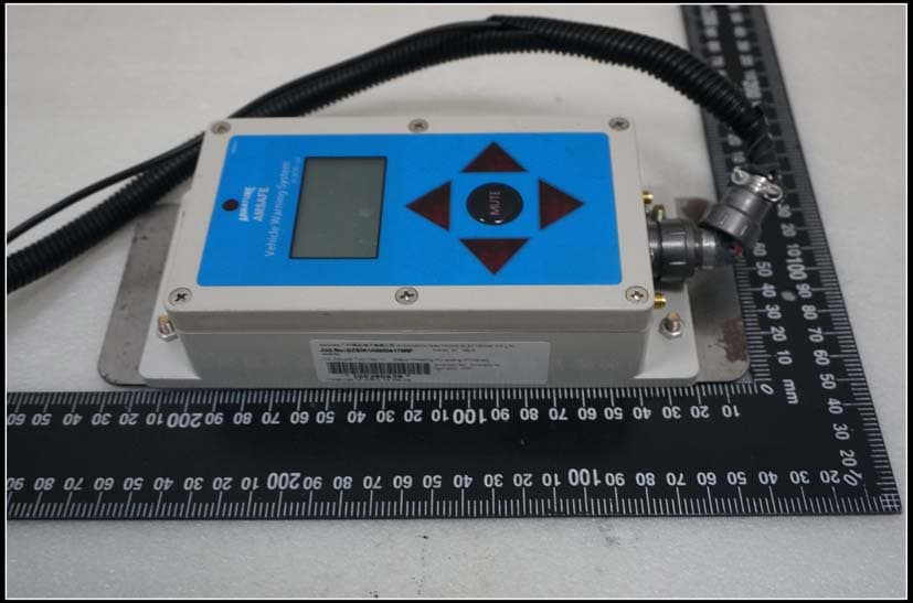
Click to zoom
Application Details
- Equipment Class
- DXX - Part 15 Low Power Communication Device Transmitter
- Date of Grant
- Jan 18, 2015
- Application Purpose
- Original Equipment
- Date of Application
- Jan 14, 2015
- Equipment Note
- Vehicle Warning System V5.10
- Frequency Range
- 2428.74800000 - 2428.74800000
- Country
- China
Documents & Files
Document Text
Text extracted from the exhibit documents filed with the FCC. Open a document above to read the original.
Users Manual
Page 1 Part I Vehicle Warning System V5.10 Host Manual 1 Installation information The host has been screwed on metal base in factory. We suggest to tie it up on forklift frame by cable tie ( packed in box) Installation example: 2 Host Dimension Page 2 Side 47m Note:Above dimension tolerance is 1mm; 2. Technical Data Host Electrical Power supply:12-28V DC Mechanical Dimension:198×92×47(mm) Environmental Work temperature:0-70 centigrade; Industrial LCD display IR remote control Radio & Range 2400.0MHz~2483.5MHz Range:0-15meter 3. Remote Control Appearance And Function Page 3 There are 11 buttons used to set host volume, detect range, timer, Personnel Tag (P-Tag) ID number register, user management etc Key Functions: 1) System: system setting, press to set time, date etc 2) Setting: management setting, to change host ID,set alarm function, set power shut off function. 3) Upload: data upload mode, 4) Range: detect rang setting, to set detect range between host to host, host to person transmitter 5) ID N/A: Enter/Delete ID which don’t need to detect. 6) Navigation: turn on or turn off Voice Navigation. Press one time to turn on, press again to turn off. The alarm will still work even the navigation function turns off. 7) Volume: there is mute, and, volume 1-3 level 8) Enter: to confirm operation, save and exit or enter next Menu 9) Exit: to exit operation or back to previous menu. 10) ▲/+:Up / plus 11) ▼/-:Down/minus 4. Remote Control Operations After turn-on the power, LCD will display as follows (It takes around 6-8 sec. to respond for the first time) Page 4 4.1 System Setting System settings menu includes, a. Timer Setting b. Delete Logs History c. Manufacturer Default Reset. Press “System” to enter system settings, choose corresponding menu via▲/▼, the selected one will be highlighted. Follow the speaker’s guide, press “Enter” to save your choosing. 4.1.1 Timer Setting Enter Timer Setting, press “Enter” button to choose the part you need to adjust. The sequence is: Year/Month/Date/Hour/ Minute/Second. Select 0-9 via ▲ or ▼ , press “Enter” to save. Press “Exit” to cancel timer setting. Press “Enter” again to confirm and exit. 4.1.2. Delete History After enter this menu, speaker will remind you whether you want to delete history. Press “Enter” to confirm delete, “Exit” to cancel delete. After deleting, LCD display will be back to menu 4.1.3. Default Reset Suggest not entering this menu if not necessary. All settings will be back to manufacturer’s default after reset. Press “Enter” to set, Press “Exit” to cancel the set. Page 5 4.2 Management Press “setting” to enter 4.2.1. Change Host ID Enter change host ID menu, press ▲ and ▼ to choose 0-9, after finishing one bit ,press “Enter” to next bit. After setting all bits, press “Enter” to save. Press “Exit” to cancel setting 4.2.2 Alarm Management Enter menu, select Turn on or turn off alarm via ▲ and ▼, then press “Enter”to save. Press “Exit” to cancel. If select turn off, it will not alarm even if system detected Personal-tag 4.2.3 Power Control Enter menu, select Turn on or Turn off via ▲ and ▼, then press “Enter” to save. Press “Exit” to cancel. Note: If choosing “Turn off power Control”, you can still drive vehicle even if the system is alarming. Page 6 4.3 N/A ID Setting N/A ID is the ID which will not be alarmed when it enter detected range. Press “ID N/A” to enter. It Include “Register N/A ID”, “Logout N/A ID”, “Check N/A ID”. Select via ▲ and ▼, then press “Enter” to next menu. 4.3.1. Register N/A ID. Enter menu, put the device ( include P-tag and host ) which needn’t alarm, within 2m of the vehicle, turn on P-tag or host , the system will automatically read p-tag or host ID number and display it’s in LCD. P-tag ID is 4 numbers, Host ID is 3 numbers. After registration all ID, press Enter to save. The System will not alarm when it, detect these registered ID. You may only register 12 Non-Detected ID. 4.3.2. Logout N/A ID Enter menu, select ID via ▲ and ▼, press “Enter” to logout, press. “Exit” to cancel. After logout, system will alarm when it enter the detected range . 4.3.3 Check N/A ID Enter menu, LCD display will list all Non-Detected ID, check via ▲ and ▼. Press “Exit” to exit. 4.4 Data Upload Mode Press “Upload”, system will broadcast: “ Has entered data upload mode, please put device within 2 meters Page 7 range of Host, during data uploading, don't move device and vehicle”. LCD display will show “Device Connecting......”. If it can’t connect within 30 seconds, and the system will broadcast “Connection failed, please check device and connect again”, the system will exit within 2 seconds. If device connect successfully within 30 seconds, the system will broadcast “Connected, begin to upload data”. Then the system will play “Uploading, hold on please” within 1 second. After uploaded, the system will automatically exit this function within 2 seconds . 4.5 Detected Range Setting Press “Range”, select option by press ▲ and ▼. Select range by press ▲ and ▼, press . “Enter” to confirm range, press “Exit” to cancel. 5 meter detect range:(± 2 meter tolerance) 10 meter detect range:(± 2.5 meter tolerance) 15 meter detect range:(± 3 meter tolerance) 4.6 Voice Navigation Select “Turn on” or “Turn off” by press “Navigation” button. Page 8 Enter to save, Exit to cancel 4.7 Volume Setting There have 4 level volume control in system,mute,1 level,2. level,3 level. Select options by press ▲ and ▼. Enter to save, Exit to cancel 4.8 Memory Full Note 6.8.1. System can store Maximum 4000 logs. When the logs reach to 3500, the system will display “Memory will be full, please upload data in time”. This message will show per hour and last 5 seconds each time. 4.8.2. When the logs reach to 4000, the system will display. “Memory is full, please upload data.” This message will show every 15 minutes and last 5 seconds each time . 5. Mute Button Page 9 RED Triangle Lights: The lights will flash when the host detects pedestrians entering the range. On normal c…
Text truncated - open the document above for the full version.
External Photos
External Photos
External Photos
System Photos
ID Label/Location Info
机动车安全管理系统 FCC ID号位置示意图 FCC ID:2AC3GVSMSV5H This device complies with Part 15 of the FCC Rules. Operation is subject to the following two conditions: (1) this device may not cause harmful interference, and (2) this device must accept any interference received, including interference that may cause undesired FCC ID:2AC3GVSMSV5P This device complies with Part 15 of the FCC Rules. Operation is subject to the following two conditions: (1) this device may not cause harmful interference, and (2) this device must accept any interference received, including interference that may cause undesired FCC ID:2AC3GVSMSV5T This device complies with Part 15 of the FCC Rules. Operation is subject to the following two conditions: (1) this device may not cause harmful interference, and (2) this device must accept any interference received, including interference that may cause undesired HOST P ‐ tag Transmitter FCC ID:2AC3GVSMSV5L This device complies with Part 15 of the FCC Rules. Operation is subject to the following two conditions: (1) this device may not cause harmful interference, and (2) this device must accept any interference received, including interference that may cause undesired Log uploader c 4CM 2CM
Internal Photos
Internal Photos
Test Report
SGS-CSTC Standards Technical Services Co., Ltd. 198 Kezhu Road, Scientech Park, Guangzhou Economic & Technological Development District, Guangzhou, China 510663 Telephone: +86 (0) 20 82155555 Fax: +86 (0) 20 82075059 Email: [email protected] Report No.: GZEM140800417801 Page: 1 of 20 FCC ID: 2AC3GVSMSV5H Jerry Chan Manager The manufacturer should ensure that all products in series production are in conformity with the product sample detailed in this report. If the product in this report is used in any configuration other than that detailed in the report, the manufacturer must ensure the new system complies with all relevant standards. The report must not be used by the client to claim product certification, approval, or endorsement by NVLAP, NIST, or any agency of the federal government. All test results in this report can be traceable to National or International Standards. This document is issued by the Company subject to its General Conditions of Service printed overleaf, available on request or accessible at www.sgs.com/terms_and_conditions.htm and, for electronic format documents, subject to Terms and Conditions for Electronic Documents at www.sgs.com/terms_e-document.htm. Attention is drawn to the limitation of liability, indemnification and jurisdiction issues defined therein. Any holder of this document is advised that information contained hereon reflects the Company’s findings at the time of its intervention only and within the limits of Client’s instructions, if any. The Company’s sole responsibility is to its Client and this document does not exonerate parties to a transaction from exercising all their rights and obligations under the transaction documents. This document cannot be reproduced except in full, without prior written approval of the Company. Any unauthorized alteration, forgery or falsification of the content or appearance of this document is unlawful and offenders may be prosecuted to the fullest extent of the law. Unless otherwise stated the results shown in this test report refer only to the sample(s) tested and such sample(s) are retained for 90 days only 1 Cover Page TEST REPORT Application No.: GZEM1408004178RF Applicant: Guangzhou Waytronic Electronics Co., Ltd. Manufacturer: Same as Applicant Factory: Same as Applicant FCC ID: 2AC3GVSMSV5H Product Name: Vehicle Warning System V5.10 Product Description: Radio transmitter with 2.4GHz as carrier Model No.: Host Standards: CFR 47 PART 15 Subpart C: 2013 section 15.249 Date of Receipt: 2014-08-12 Date of Test: 2014-09-03 to 2014-10-14 Date of Issue: 2015-01-12 Test Result : Pass* * In the configuration tested, the EUT complied with the standards specified above. SGS-CSTC Standards Technical Services Co., Ltd. Report No.: GZEM140800417801 Page: 2 of 20 FCC ID: 2AC3GVSMSV5H This document is issued by the Company subject to its General Conditions of Service printed overleaf, available on request or accessible at www.sgs.com/terms_and_conditions.htm and, for electronic format documents, subject to Terms and Conditions for Electronic Documents at www.sgs.com/terms_e-document.htm. Attention is drawn to the limitation of liability, indemnification and jurisdiction issues defined therein. Any holder of this document is advised that information contained hereon reflects the Company’s findings at the time of its intervention only and within the limits of Client’s instructions, if any. The Company’s sole responsibility is to its Client and this document does not exonerate parties to a transaction from exercising all their rights and obligations under the transaction documents. This document cannot be reproduced except in full, without prior written approval of the Company. Any unauthorized alteration, forgery or falsification of the content or appearance of this document is unlawful and offenders may be prosecuted to the fullest extent of the law. Unless otherwise stated the results shown in this test report refer only to the sample(s) tested and such sample(s) are retained for 90 days only. 2 Version Revision Record Version Chapter Date Modifier Remark 00 2015-01-12 Original Authorized for issue by: Tested By 2014-09-03 to 2014-10-14 (Jack Liang) /Project Engineer Date Prepared By 2014-11-13 (Millie Li) /Clerk Date Checked By 2014-11-24 (Jerry Chan)/Reviewer Date SGS-CSTC Standards Technical Services Co., Ltd. Report No.: GZEM140800417801 Page: 3 of 20 FCC ID: 2AC3GVSMSV5H This document is issued by the Company subject to its General Conditions of Service printed overleaf, available on request or accessible at www.sgs.com/terms_and_conditions.htm and, for electronic format documents, subject to Terms and Conditions for Electronic Documents at www.sgs.com/terms_e-document.htm. Attention is drawn to the limitation of liability, indemnification and jurisdiction issues defined therein. Any holder of this document is advised that information contained hereon reflects the Company’s findings at the time of its intervention only and within the limits of Client’s instructions, if any. The Company’s sole responsibility is to its Client and this document does not exonerate parties to a transaction from exercising all their rights and obligations under the transaction documents. This document cannot be reproduced except in full, without prior written approval of the Company. Any unauthorized alteration, forgery or falsification of the content or appearance of this document is unlawful and offenders may be prosecuted to the fullest extent of the law. Unless otherwise stated the results shown in this test report refer only to the sample(s) tested and such sample(s) are retained for 90 days only. 3 Test Summary Test Test Requirement Test method Result Field Strength of Fundamental FCC PART 15 C section 15.249 (a) ANSI C63.10: Clause 6.6 PASS Field Strength of Unwanted Emissions FCC PART 15 C section 15.249 (a) section 15.249 (d) ANSI C63.10: Clause 6.4, 6.6 and 6.7 PASS Band Edges FCC PART 15 C section 15.249 (d) ANSI C63.10: Clause…
Text truncated - open the document above for the full version.
Test Setup Photos
Test Setup Photo 1.1 RADIATED EMISSION TEST SETUP Below 1G Abov e 1G
Contact Information
Applicant
guojun Li(Company boss)
Technical Contact
SGS-CSTC Standards Technical Services Co., LtdJack Liang
[email protected]86-20-82155330
198 KEZHU Road, Scientech Park, Guangzhou · Guangzhou, Guangdong · China
Non-Technical Contact
SGS-CSTC Standards Technical Services Co., LtdJune Chen
[email protected]86-20-82155330
Test Firm
SGS-CSTC Standards Technical Services Co., LtdJerry Chan
Technical Specifications
| # | Rule Parts | Frequency Range | Power Output |
|---|---|---|---|
| 1 | 15C | 2.43 GHz - 2.43 GHz | - |
Other Applications from Guangzhou Waytronic Electronics Co., Ltd.
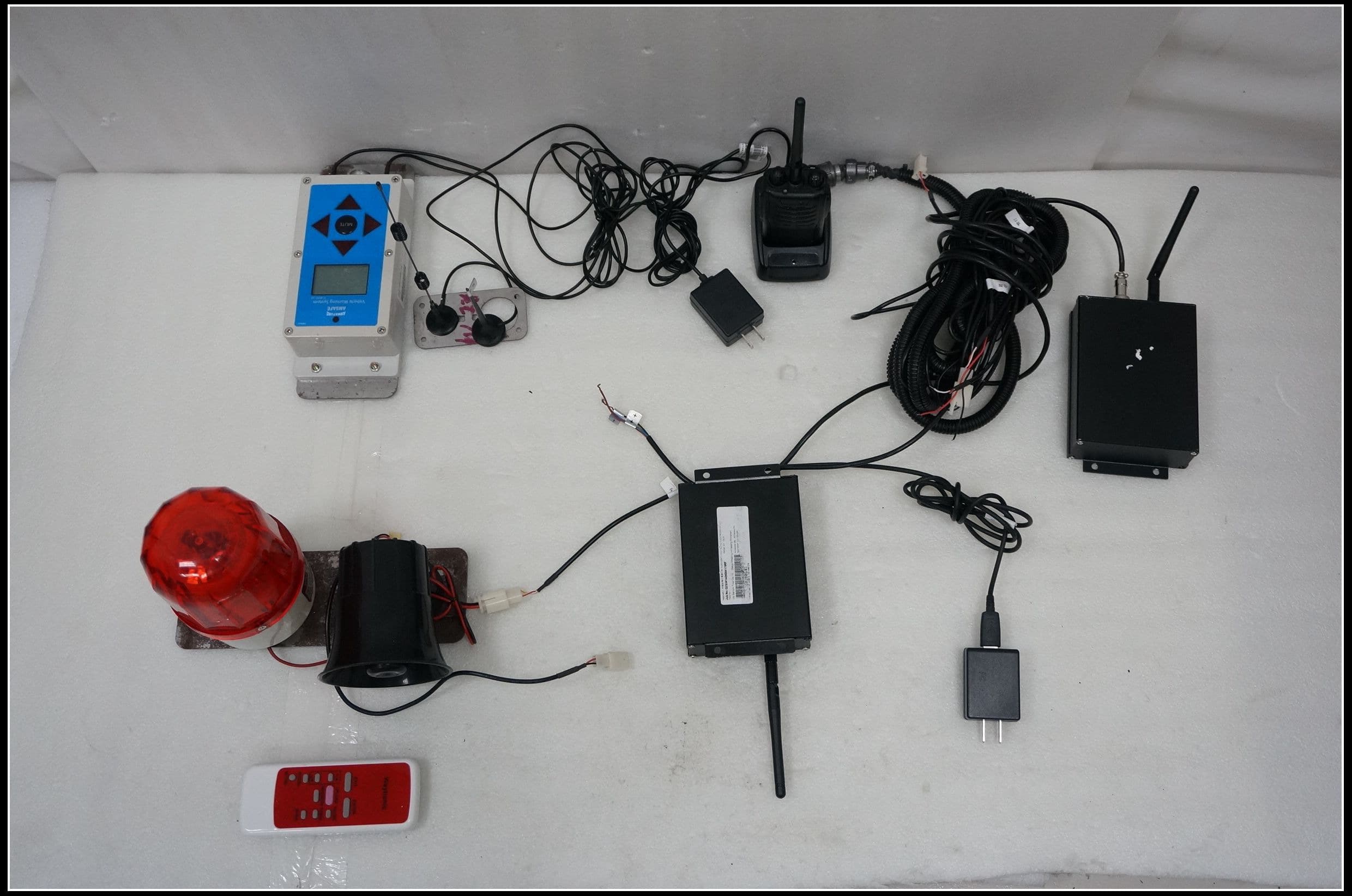
2AC3GVSMSV5T
Jan 18, 2015Vehicle Warning System V5.10
Equipment Class
DXX - Part 15 Low Power Communication Device Transmitter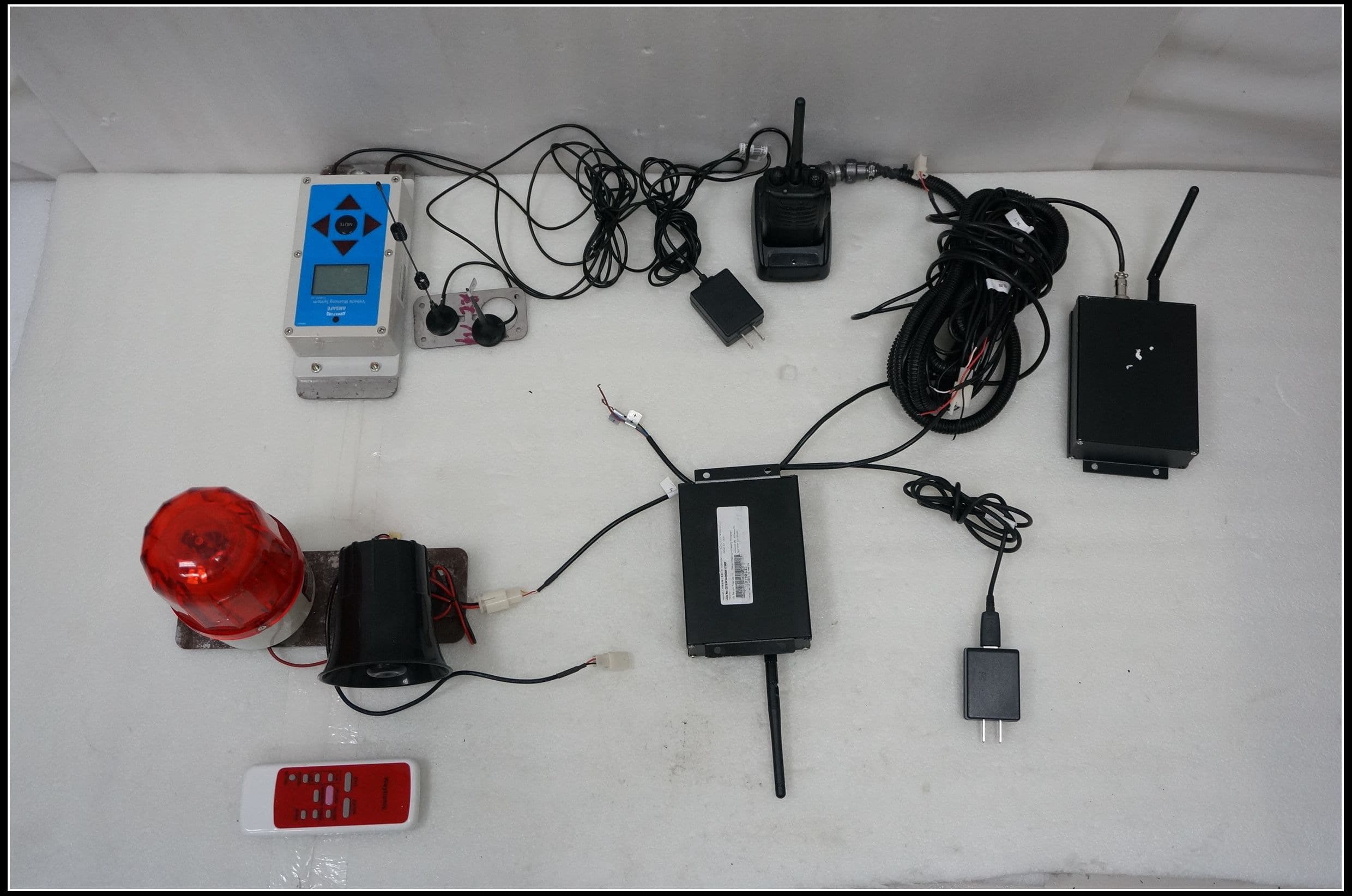
2AC3GVSMSV5P
Jan 18, 2015Vehicle Warning System V5.10
Equipment Class
DXX - Part 15 Low Power Communication Device Transmitter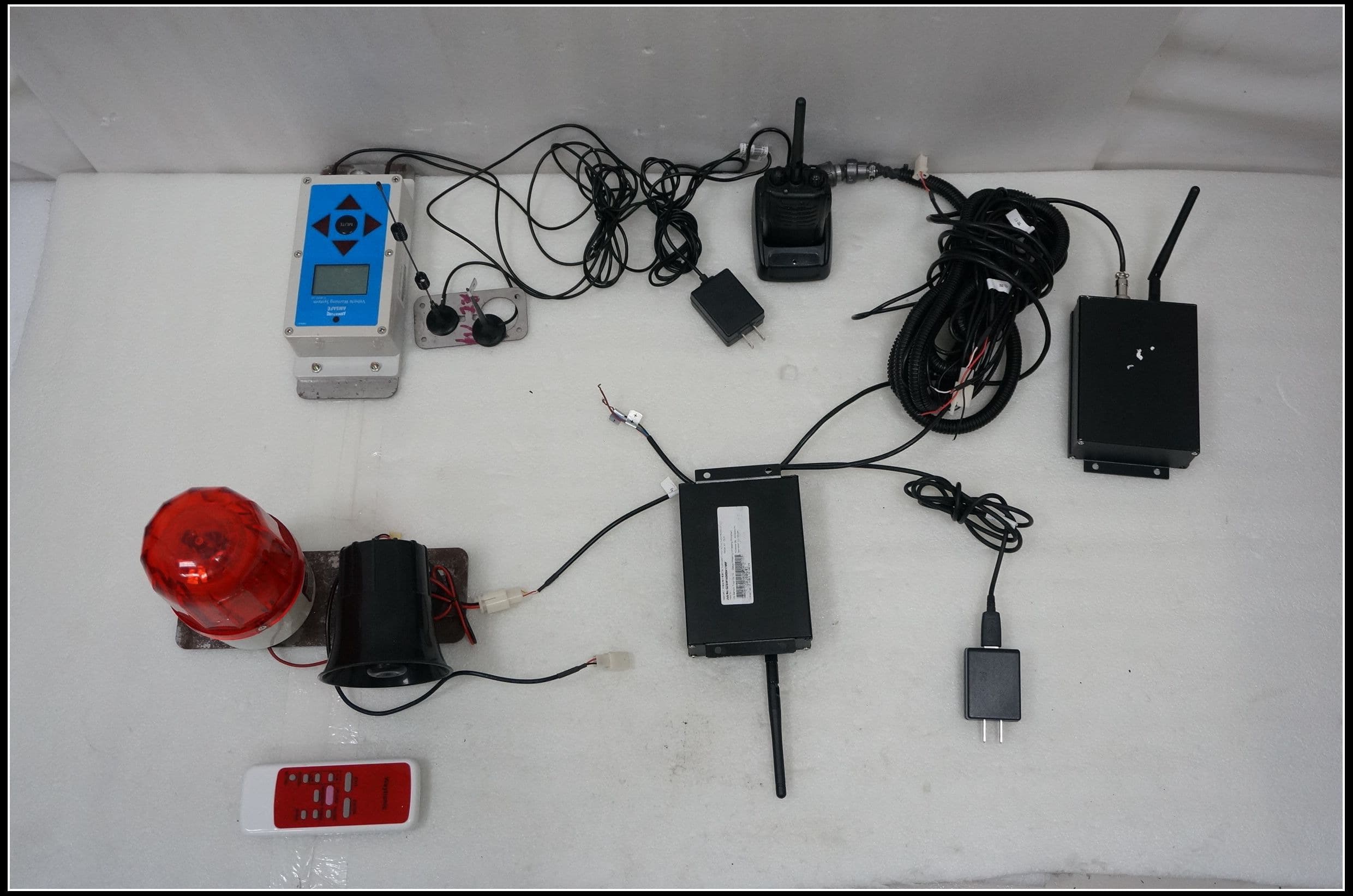
2AC3GVSMSV5L
Jan 18, 2015Vehicle Warning System V5.10
Equipment Class
DXX - Part 15 Low Power Communication Device Transmitter