2AC3Z-CAC1014000Wireless Sensor
ACOEM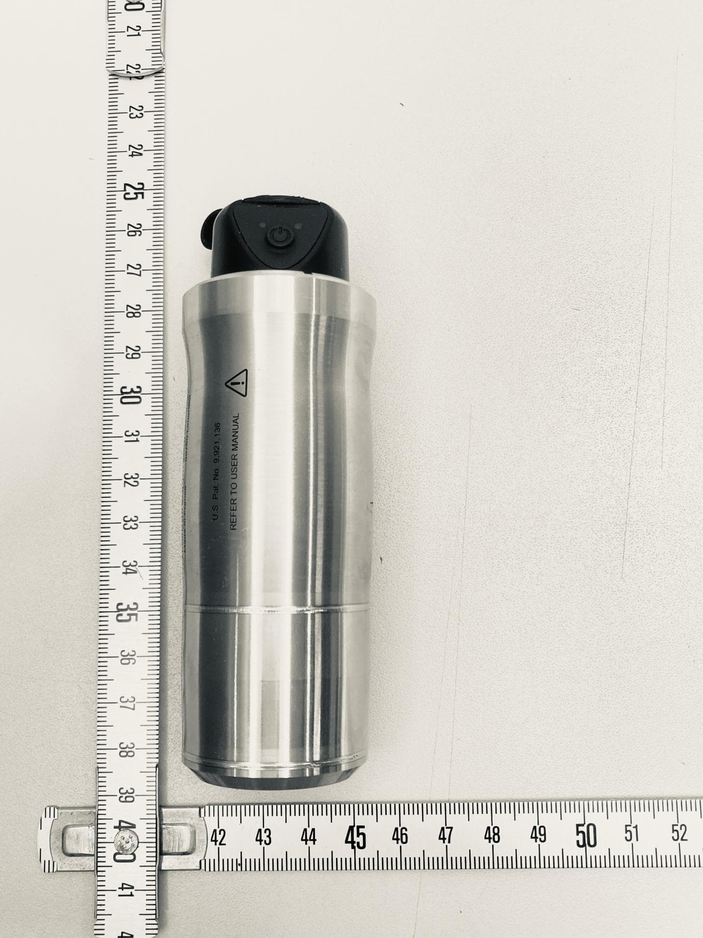
Click to zoom
Application Details
- Equipment Class
- JBP - Part 15 Class B Computing Device Peripheral
- Date of Grant
- Aug 27, 2026
- Application Purpose
- Original Equipment
- Equipment Note
- Wireless Sensor
- Company
- ACOEM
- Country
- France
Documents & Files
Document Text
Text extracted from the exhibit documents filed with the FCC. Open a document above to read the original.
Users Manual
CAC1014000 Wireless accelerometer SAFETY INSTRUCTIONS INSTRUCTIONS DE SECURITE INSTRUCCIONES DE SECURIDAD INSTRUÇÕES DE SEGURANÇA ИНСТРУКЦИЯ ПО БЕЗОПАСНОМУ ИСПОЛЬЗОВАНИЮ NOT3123 – December 2025 A acoem.com Copyright © 2025, ACOEM RP SAFETY INSTRUCTIONS Before any use, carefully read these safety instructions and the operating instructions. The safety of the device and the user is compromised in case of use unforeseen by ACOEM. Dismantling the instrument for an internal operation is forbidden. The only part for which dismantling is allowed is the hatch providing access to the USB connector. All the spare parts must be provided by the manufacturer Warning symbol listing Warning: Whenever this symbol is present on the device, refer to the essential safety warning and instructions for use Symbol Meaning Warning: Whenever this symbol is present on the device, refer to the essential safety warning and instructions for use Please refer to the EU declaration of conformity Refer to Dismantling/recycling General rules - Comply with the safety instructions listed hereafter. - Keep these safety instructions for future reference. - Comply with the operating instructions listed in the user manual. Verification of the overall condition - Upon each use, check the overall condition of the unit and its accessories. - Check that the housing is not cracked, broken or abnormally distorted. - Check the condition of the opening cap of the USB connector. - In case of a defect, have the defective part(s) repaired or replaced. Electric connections - Power Supply: 5V DC, 2A (see Main power supply block). - Do not exceed maximum input voltage on the USB connector: maximum input voltage = 5 V DC. - Do not exceed maximum input voltage for the power supply delivered by the mains block. Operating environment The device is designed to operate in the normal operating environment of IEC61010-1 ● altitude up to 2000 m; ● temperature from 0°C to 45°C; ● pollution rating 2. And the following extended conditions: ● altitude up to 4000 m ● Punctual outdoor use, with the USB plug in place and without the charger; ● ambient temperatures from -20°C to 60°C; ● 95% non-condensing humidity - This device must NOT be used in ATEX zones or in the presence of explosive gases/dusts. - Do not install the sensor on rotating parts. - Always use the instrument with the USB connector cap closed. Check the condition of the cap and its waterproofness at each implementation. If the cap is defective, please contact our after-sales department to have it replaced. Battery - The battery cannot be changed by the user and the instrument must be returned to the factory for battery replacement. Please contact our after-sales department for this operation. - Do not attempt to replace the battery. This operation could affect the product safety (furthermore, metrological performances could also be affected during this operation). - Do not open or dismount the battery pack. The pack includes essential safety protections and assembly that should in no event be modified. - Do not place the battery into fire or close to any other temperature source (> 70°C). This action may cause overheating, even start a fire. This type of use may also lead to degraded performances and to a significantly reduced lifetime for the battery. - The battery should only be recharged at a temperature between 5° and 40°C. - Immediately disconnect the charger in the event of one of the following situations: ● unusual odour ● unusually high temperature Main power supply block - The external power must be compliant with IEC 62368-1 (ES1 / PS2). - The power supply is the main disconnect device in the system and as such should remain always perfectly accessible and disconnectable. - The mains power block should only be used away from rain or any other water splash. - The Unit should be used away from rain or any other water splash when connected to the mains power block (office environment). - Comply with the network power supply specifications (listed on the charger) for the power supply of the mains block. - During charging, the operator shall limit the presence of flammable products next to the unit and the mains power block. - To connect the power supply, remove the USB plug, plug the USB plug of the block on the socket, then connect the power to the electrical outlet. Proceed in the reverse order for disconnect. Radio Radio (Wi-Fi) has been qualified to ensure EMC and personal safety. This qualification is valid only with the instrument’s internal antenna. This device complies with FCC, IC RF radiation exposure limits set forth for general population. This device must be installed to provide a separation distance of at least 20cm from all persons and must not be co-located or operating in conjunction with any other antenna or transmitter. Caution: Changes or modifications not expressly approved by the party responsible for compliance could void the user's authority to operate the equipment. FCC: This device complies with Part 15 of the FCC Rules. Operation is subject to the following two conditions: (1) this device may not cause harmful interference, and (2) this device must accept any interference received, including interference that may cause undesired operation. NOTE: This equipment has been tested and found to comply with the limits for a Class B digital device, pursuant to part 15 of the FCC Rules. These limits are designed to provide reasonable protection against harmful interference in a residential installation. This equipment generates, uses and can radiate radio frequency energy and, if not installed and used in accordance with the instruction, may cause harmful interference to radio communications. However, there is no guarantee that interference will not occur in a particular installation. If this equipment does cause harmful interference to radio or television reception which can be determined by turning the equipment off and on, the user is encouraged to try to correct …
Text truncated - open the document above for the full version.
Users Manual
WELCOME TO OUR WORLD For more than 50 years, ACOEM has helped industries throughout the world to achieve more profitable and sustainable production. We have reached where we are today by having the courage to think beyond the norm and follow slightly unconventional paths. We have had the courage to make mistakes and find new directions. Through our resolve, ambition and knowledge we have become a global player and a leader in innovative, user-friendly reliability solutions. SUSTAINABLE INNOVATIONS During our 50+ years in this industry, we have explored, tweaked and tested more than anyone. Some might say we are incurable innovators whereas others might say that we are highly focused. They both probably have a point. If we had not been devoted and ambitious, we would not have been the first in the field of laser alignment to have a touch screen. Nor would we have been pioneers in the use of visible lasers and dual measurement heads. Nor would we have been the first to bring a wireless vibration sensor for machine diagnostics. We are now the first to provide our customers with combined alignment and diagnostic solutions on standard mobile devices. Over the years, we have learnt to never compromise on quality, and we are constantly in search of new, unexplored opportunities by combining advanced technology with design and function. By doing so, we have become the leading innovator in our industry. Not only do we minimize wear, production stoppages and costs, we also help save the environment. Natural resources are in short supply and if we can contribute to a more sustainable world by making it a little bit straighter, we couldn't be happier. 1.1 TRUE COMMITMENT One reason for our success is our solid commitment. We have ensured that we remain attentive to constantly pick up on the needs of the market. Our expert employees and dedicated dealers in over 70 countries are undoubtedly our most important asset. Satisfaction and team spirit are of particular importance to us and are consistently at the top of our priority list. With experience from a wide range of industries and manufacturing processes, we are fully aware of the problems and needs of our end-customers. We are passionate about what we do and we are driven by the desire to eliminate anything in the industry worldwide that may be even slightly out of line. PURE USABILITY Our design and user-friendliness are carefully interwoven. As we develop new products, they also become cleaner, smarter, more functional and more robust. An industrial environment is demanding, infinitely more difficult to work in and inevitably subject to time pressure. There is no place for equipment with unnecessary functions, complicated interfaces and that is difficult to assemble. Usability and user friendliness mean everything, not only to us but also to our customers. We have designed products that are easy to learn and can be incorporated quickly. By removing non-essential functions, we make life less difficult for our users – and probably a little more difficult for our competitors. 1.2 END USER LICENSE AGREEMENT The rights to use the software in this product are offered only on the conditions that you agree to all the terms stated below, i.e. the end user agreement. By using this product, you agree to be bound by this agreement. If you do not accept this agreement your sole remedy is to return the entire unused product, hardware and software, promptly to your place of purchase for a refund. The user is granted a single license to use the software contained in this product. Use is only permitted on the hardware it has been installed on at the time of purchase. The software may not be removed from the hardware. The software contained in the system is the property of ACOEM group, any copying or redistribution is strictly prohibited. Modifying, disassembling, reverse engineering or decompiling the system or any part thereof is strictly prohibited. Disclaimer of warranties: To the maximum extent permitted by applicable law, ACOEM and its suppliers provide the software contained in this product ‘as is’ and with all faults, and hereby disclaim all other warranties either expressed, implied or statutory. Limited liability: No liability shall exceed the price of the product, and the sole remedy, if any, to any claim shall be a right of return and refund. ACOEM or its suppliers shall, to the maximum extent permitted by applicable law, not be liable to any indirect, special, incidental, punitive, and consequential damages arising from the use of the system or any part thereof, authorized or unauthorized. ACOEM group is headquartered in Lyon, France. For more information please visit acoem.com 1.3 EU DECLARATION OF CONFORMITY In accordance with: 2014/35/EU Low voltage Directive 2014/30/EU Electromagnetic compatibility Directive 2014/53/EU RED (Radio equipment Directive) 2011/65/EU RoHS Directive Type of equipment Vibration Sensor Brand name or trade mark ACOEM Type designation(s)/Model no(s) VT-301 / CAC1014000 Manufacturer’s name, address, telephone & fax no ACOEM RP SAS 200 allée des Ormeaux 69760 Limonest France Tel: +33 4 72524800 Fax: +33 4 42901766 Company certification ISO 14001:2015 – 0027566 ISO 9001:2015 – 0027567 ISO 45001:2018 – 0027568 Issued by LRQA France SAS, for and on behalf of: Lloyd's Register Quality Assurance Limited 2.1 The following standards and/or technical specifications, which comply with good engineering practice in safety matters in force within the EEA, have been applied: Safety requirements for electrical equipment: IEC 61010-1 :2010 + A1 :2016. Electromagnetic compatibility: EN IEC 61326-1 (2021) ETSI EN 301 489-1 V2.2.3 ETSI EN 301 489-17 V3.3.1 Radio : ETSI EN 300 328-1 v2.1.1, EN 62311 (2008) Additional information The product was CE-marked in 2025. As manufacturer, we declare under our sole responsibility that the equipment follows the provisions of the Directives stated above. Date and place of issue Limonest, 2021-08-19 Signatu…
Text truncated - open the document above for the full version.
Cover Letter(s)
Letter of Agency July 16, 2026 To: Federal Communications Commission 7435 Oakland Mills Road Columbia, MD 21046-1609 IIA Lab Services, LLC. 13146 NW 86th Drive, Suite 400 Alachua, FL 32615- United States We, the undersigned ACOEM hereby authorizes Majid MOURZAGH, LCIE SUD EST, to act on our behalf in all matters relating to all processes required for FCC certification of our devices. Any and all acts carried out by the above agent on our behalf shall have the same effects as acts of our own. This authorization is valid until: December 31th, 2026 If you have any questions regarding this authorization, let us know please. Sincerely, Fabien CONDEMINE Signature:
External Photos
Page 1/7 EXTERNAL PHOTOS OF EQUIPMENT FCCID: 2AC3Z-CAC1014000 Page 2/7 Page 3/7 Page 4/7 Page 5/7 Page 6/7 Page 7/7
ID Label/Location Info
Page 1/2 PRODUCT LABELING FCCID: 2AC3Z-CAC1014000 Page 2/2 Label Location Information: Label on the final product marking is laser engraved on the body of the sensor
Internal Photos
Page 1/9 INTERNAL PHOTOS OF EQUIPMENT FCCID: 2AC3Z-CAC1014000 Page 2/9 Page 3/9 RF Antenna Page 4/9 Page 5/9 Page 6/9 Page 7/9 Page 8/9 Page 9/9
RF Exposure Info
LCIE SUD EST Laboratoire de Moirans Z.I. Centr’Alp 170, Rue de Chatagnon 38430 MOIRANS - FRANCE FCCID: 2AC3Z-CAC1014000 According to KDB 447498 D01 General RF Exposure Guidance v06 4.3.1 Standalone SAR test exclusion considerations LCIE SUD EST Laboratoire de Moirans Z.I. Centr’Alp 170, Rue de Chatagnon 38430 MOIRANS - FRANCE Limit for General Population/ Uncontrolled Exposure : 47 CFR 1.1310 where: S = power density P = power input to the antenna G = power gain of the antenna in the direction of interest relative to an isotropic radiator R = distance to the center of radiation of the antenna Prediction Frequency MHz Conducted Output Power dBm Max Antenna Gain dBi Distance cm Power Density mW/cm2 Limit mW/cm2 2412 11.26 1.3 20 0.0036 1.00 2437 10.81 1.3 20 0.0032 1.00 2462 10.98 1.3 20 0.0034 1.00 Conclusion: Therefore our device complies with FCC’s RF radiation exposure limits for general population without SAR evaluation with at least 20cm separation from all persons and must not be co-located or operating in conjunction with any other antenna or transmitter.
Test Report
Dimensions: [mm] 1,1 ±0,15 3,5 ±0,2 7,6 ±0,3 0,55 ±0,15 0,8 ±0,2 0,5 ±0,3 1 3 2 4 5 6 Scale - 3:1 Recommended Land Pattern: [mm] 3,9 1,2 1,26,6 0,8 0,35 1 2 34 5 6 Scale - 3:1 Schematic: Electrical Properties: PropertiesTest conditionsValueUnitTol. Frequency Range Min & Max2400-2500MHz Frequency Rangef2400-2500 MHz VSWR2400 - 2500 MHz2max. ImpedanceZ50Ωtyp. Peak Gain G peak 2400 - 2500 MHz1.3dBityp. Certification: RoHS ApprovalCompliant [2011/65/EU&2015/863] REACh ApprovalConform or declared [(EC)1907/2006] Halogen FreeConform [JEDEC JS709B] Halogen FreeConform [IEC 61249-2-21] General Information: Operating Temperature-40 °C up to +85 °C Storage Conditions (in original packaging) < 40 °C ; < 75 °C Moisture Sensitivity Level (MSL)1 Test Board7488920EB Test conditions of Electrical Properties: +20 °C, 33 % rH if not specified differently Würth Elektronik eiSos GmbH & Co. KG EMC & Inductive Solutions Max-Eyth-Str. 1 74638 Waldenburg Germany Tel. +49 (0) 79 42 945 - 0 www.we-online.com [email protected] CHECKEDREVISIONDATE (YYYY-MM-DD)GENERAL TOLERANCEPROJECTION METHOD AlSt002.0012024-10-28DIN ISO 2768-1m DESCRIPTION WE-MCA Multilayer Chip Antenna ORDER CODE 7488920245 SIZE/TYPEBUSINESS UNITSTATUSPAGE 7.6 x 3.5 mm eiSosValid1/11 This electronic component has been designed and developed for usage in general electronic equipment only. This product is not authorized for use in equipment where a higher safety standard and reliability standard is especially required or where a failure of the product is reasonably expected to cause severe personal injury or death, unless the parties have executed an agreement specifically governing such use. Moreover Würth Elektronik eiSos GmbH & Co KG products are neither designed nor intended for use in areas such as military, aerospace, aviation, nuclear control, submarine, transportation, transportation signal, disaster prevention, medical, public information network etc.. Würth Elektronik eiSos GmbH & Co KG must be informed about the intent of such usage before the design-in stage. In addition, sufficient reliability evaluation checks for safety must be performed on every electronic component which is used in electrical circuits that require high safety and reliability functions or performance. Recommended Matching Circuit: [mm] Without Matching Circuit: 9,0 1,2 3,90,8 6,61,2 The matching circuit shown has been designed based on the Würth Elektronik evaluation board and cannot be reused. It is recommended to leave a 'Pi' or 'T' type matching circuit space for antenna matching circuit for other boards. GND GND Feed Point NC NC NC Würth Elektronik eiSos GmbH & Co. KG EMC & Inductive Solutions Max-Eyth-Str. 1 74638 Waldenburg Germany Tel. +49 (0) 79 42 945 - 0 www.we-online.com [email protected] CHECKEDREVISIONDATE (YYYY-MM-DD)GENERAL TOLERANCEPROJECTION METHOD AlSt002.0012024-10-28DIN ISO 2768-1m DESCRIPTION WE-MCA Multilayer Chip Antenna ORDER CODE 7488920245 SIZE/TYPEBUSINESS UNITSTATUSPAGE 7.6 x 3.5 mm eiSosValid2/11 This electronic component has been designed and developed for usage in general electronic equipment only. This product is not authorized for use in equipment where a higher safety standard and reliability standard is especially required or where a failure of the product is reasonably expected to cause severe personal injury or death, unless the parties have executed an agreement specifically governing such use. Moreover Würth Elektronik eiSos GmbH & Co KG products are neither designed nor intended for use in areas such as military, aerospace, aviation, nuclear control, submarine, transportation, transportation signal, disaster prevention, medical, public information network etc.. Würth Elektronik eiSos GmbH & Co KG must be informed about the intent of such usage before the design-in stage. In addition, sufficient reliability evaluation checks for safety must be performed on every electronic component which is used in electrical circuits that require high safety and reliability functions or performance. Evaluation Board: [mm] PAJ20101 PAJ2010J1 COJ201 PAU$260101 PAU$260102 PAU$260103 PAU$260104 PAU$260105 PAU$260106 COU$2601 -35 -30 -25 -20 -15 -10 -5 0 1234 Return Loss [dB ] Frequency [GHz] S11 Würth Elektronik eiSos GmbH & Co. KG EMC & Inductive Solutions Max-Eyth-Str. 1 74638 Waldenburg Germany Tel. +49 (0) 79 42 945 - 0 www.we-online.com [email protected] CHECKEDREVISIONDATE (YYYY-MM-DD)GENERAL TOLERANCEPROJECTION METHOD AlSt002.0012024-10-28DIN ISO 2768-1m DESCRIPTION WE-MCA Multilayer Chip Antenna ORDER CODE 7488920245 SIZE/TYPEBUSINESS UNITSTATUSPAGE 7.6 x 3.5 mm eiSosValid3/11 This electronic component has been designed and developed for usage in general electronic equipment only. This product is not authorized for use in equipment where a higher safety standard and reliability standard is especially required or where a failure of the product is reasonably expected to cause severe personal injury or death, unless the parties have executed an agreement specifically governing such use. Moreover Würth Elektronik eiSos GmbH & Co KG products are neither designed nor intended for use in areas such as military, aerospace, aviation, nuclear control, submarine, transportation, transportation signal, disaster prevention, medical, public information network etc.. Würth Elektronik eiSos GmbH & Co KG must be informed about the intent of such usage before the design-in stage. In addition, sufficient reliability evaluation checks for safety must be performed on every electronic component which is used in electrical circuits that require high safety and reliability functions or performance. XY-cut scanning direction: 180 ° 270 ° 90 ° 0 ° x y z Radiation Pattern @ 2.45 GHz: +5 -5 -15 -25 0 -10 -20 1 16 31 46 61 76 91 106 121 136 151 166 181 196 211 226 241 256 271 286 301 316 331 346 361 376 391 406 421 436 451 466 481 496 511 526 541 556 571 586 601 616 631 646 661 676 691 706 721 736 751 766 781 796 811 826 841 856 871 886 901 916 931 946 961 976…
Text truncated - open the document above for the full version.
Test Report
Template : January 7 th , 2026 Reproduction of this document is only authorized in its complete form. Any partial reproduction or any insertion of results in an accompanying text with a view to their distribution must receive prior and formal agreement from LCIE. This document results from tests carried out on a specimen, sample or test piece. It does not prejudge the conformity of all the products manufactured to the object tested. Unless otherwise indicated or rule specified by the test method, the decision of conformity does not take into account measurement uncertainty. It in no way prejudges a certification decision. The accreditation of the COFRAC Testing Section attests to the technical competence of the laboratories for the tests covered by the accreditation only. If certain tests mentioned in this report were carried out outside the framework of COFRAC accreditation, they are identified by the symbol . LCIE Laboratoire Central des Industries Electriques Une société Bureau Veritas Z.I Centr'alp 170, Rue de Chatagnon 38430 Moirans FRANCE Tél. + 33 4 76 07 36 36 [email protected] www.lcie.fr SAS au capital de 15 745 984€ / RCS Nanterre B 408 363 174 / N° TVA intracommunautaire FR01 408 363 174 / N°SIRET 408 363 174 00017 Accreditation N°1-7429 Scope available on www.cofrac.fr TEST REPORT N°: 26716359-817679-A(FILE#10721384) Version: 02 Subject Electromagnetic compatibility tests according to the standards: FCC CFR 47 Part 15, Subpart B ANSI C63.4 / ANSI C63.4a ICES-003 Issued to ACOEM RP 200 ALL DES ORMEAUX 69760 – LIMONEST FRANCE Apparatus under test Product Wireless Sensor Trade mark ACOEM Manufacturer ACOEM RP Family range Wireless Sensor VT301 Model under test CAC1014000 Serial number 30031 FCCID 2AC3Z-CAC1014000 IC 12336A-CAC1014000 Conclusion See Test Program chapter Test date March 05, 2026 to March 13, 2026 Test location LCIE Grenoble – Site de Moirans FCC Test site FR0008 - 197516 (MOI) ISED Test site 6500A (MOI) Sample receipt date March 03, 2026 Composition of document 24 pages Document issued on August 17, 2026 Written by : Approved by : Marlon BOUBY Majid MOURZAGH Tests operator Technical manager TEST REPORT N°26716359-817679-A(FILE#10721384) Version : 02 Page 2/24 PUBLICATION HISTORY Version Date Author Modification 01 March 30, 2026 Majid MOURZAGH Creation of the document 02 August 17, 2026 Marlon BOUBY Coorection FCC ID on page 1 Each new edition of this test report replaces and cancels the previous edition. The control of the old editions of report is under responsibility of client. TEST REPORT N°26716359-817679-A(FILE#10721384) Version : 02 Page 3/24 SUMMARY 1. TEST PROGRAM ............................................................................................................................. 4 2. EQUIPMENT UNDER TEST: CONFIGURATION (DECLARED BY PROVIDER) .............................. 7 3. LABORATORY EQUIPMENT AND METHODOLOGY ...................................................................... 9 4. MEASUREMENT OF CONDUCTED EMISSION ............................................................................ 10 5. MEASUREMENT OF RADIATED EMISSION ................................................................................. 17 6. UNCERTAINTIES CHART .............................................................................................................. 23 TEST REPORT N°26716359-817679-A(FILE#10721384) Version : 02 Page 4/24 1. TEST PROGRAM 1.1. FCC PART15B Standard: ✓ FCC Part 15, Subpart B (Digital Devices) ✓ ANSI C63.4 (2014) / ANSI C63.4a (2017) 1.1.1. Requirements for disturbance emissions – Class B EMISSION TEST LIMITS RESULTS (Comments) Conducted emission 150kHz-30MHz FCC §15.107 Access: AC power PASS Frequency Quasi-peak Average 150-500kHz 66 to 56 dBμV 56 to 46 dBμV 0.5-5MHz 56 dBμV 46 dBμV 5-30MHz 60 dBμV 50 dBμV Radiated emission 30MHz-1GHz FCC §15.109 Access: Enclosure port of ancillary equipment PASS Frequency Quasi-peak @3m 30MHz-88MHz 40.0 dBμV/m 88MHz-216MHz 43.5 dBμV/m 216MHz-960MHz 46.0 dBμV/m Above 960MHz 54.0 dBμV/m Radiated emission 1GHz-12.75GHz* FCC §15.109 Access: Enclosure port of ancillary equipment PASS Frequency Peak @3m Average @3m 1- 12.75GHz 74.0 dBμV/m 54.0 dBμV/m NA: Not Applicable / NP: Not Performed, not requested by the customer (It cannot be taken into account for the declaration of conformity) D : Divergence, the last version is used to make it possible to test the product with the standard which describes the current state of the art and thus to answer as well as possible his environment of final use. If this test is covered by the COFRAC accreditation, the declaration of conformity for product standard only are carried out outside the framework of accreditation. *§15.33: The highest internal source of a testing device is defined like more the highest frequency generated or used in the testing device or on which the testing device works or agrees. - If the highest frequency of the internal sources of the testing device is lower than 108 MHz, measurement must be only performed until 1GHz. - If the highest frequency of the internal sources of the testing device ranges between 108 MHz and 500 MHz, measurement must be only performed until 2GHz. - If the highest frequency of the internal sources of the testing device ranges between 500 MHz and 1 GHz, measurement must be only performed until 5GHz. If the highest frequency of the internal sources of the testing device is above 1 GHz, measurement must be only performed until 5 times the highest frequency or 40 GHz, while taking smallest of both. Special condition for intentional radiator: TEST REPORT N°26716359-817679-A(FILE#10721384) Version : 02 Page 5/24 1.2. ICES-003 (2020) Standard: ✓ ANSI C63.4 (2014) / ANSI C63.4a (2017) ✓ ICES-003 (2020) 1.2.1. Requirements for disturbance emissions – Class B EMISSION TEST LIMITS RESULTS (Comments) Conducted emission 150kHz-30MHz ICES-003 §3.2.1 Access: AC power PASS Frequency Quasi-peak Average 150-500kHz 66 to …
Text truncated - open the document above for the full version.
Test Setup Photos
Page 1/3 CONDUCTED AND RADIATED MEASUREMENT PHOTO FCCID: 2AC3Z-CAC1014000 1.1 Conducted emission Photo of AC Power Line Conducted Emissions Page 2/3 1.2 Radiated emissions Photo in anechoic chamber – Frequency <1GHz Photo on OATS Page 3/3 Axis XY Axis Z Photo in anechoic chamber – Frequency >1GHz
Contact Information
Applicant
FABIEN CONDEMINE
[email protected]Fax: 33472524747
Technical Contact
AOCEM USA Inc.Damalia Sullivan
530 Southlake Blvd · North Chesterfield, Virginia, 23236 · United States
Test Firm
LCIE Etablissement Sud EstAnthony MERLIN
Technical Specifications
| # | Rule Parts | Frequency Range | Power Output |
|---|---|---|---|
| 1 | 15B | - | - |
Other Applications from ACOEM
2AC3Z-EGL1102
Mar 11, 2015RADIO FREQUENCY SENSOR
Equipment Class
DTS - Digital Transmission System
2AC3Z-CAC1005000
Mar 11, 2015RADIO FREQUENCY SENSOR
Equipment Class
DTS - Digital Transmission System
2AC3Z-EGL1101
Mar 11, 2015GATEWAY FOR RADIO FREQUENCY SENSOR
Equipment Class
DTS - Digital Transmission System