2AC4C-AU430001LGCTelemetry system for Pressure and Temperature
Forsythe Technologies Worldwide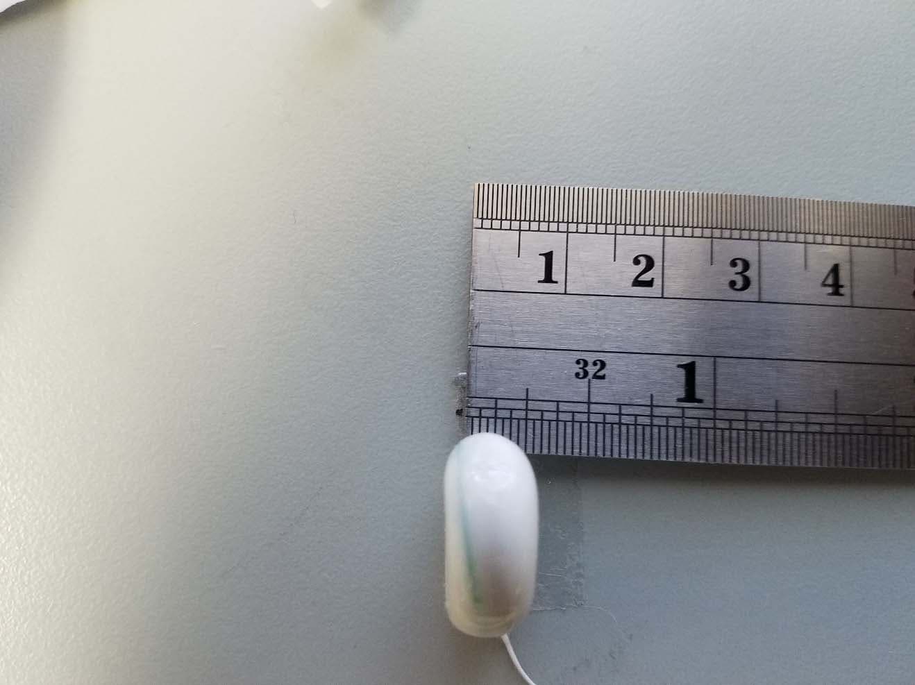
Click to zoom
Application Details
- Equipment Class
- DXX - Part 15 Low Power Communication Device Transmitter
- Date of Grant
- Jan 12, 2020
- Application Purpose
- Original Equipment
- Date of Application
- Jan 07, 2020
- Equipment Note
- Telemetry system for Pressure and Temperature
- Frequency Range
- 915.60000000 - 915.60000000
- Country
- United States
Documents & Files
Document Text
Text extracted from the exhibit documents filed with the FCC. Open a document above to read the original.
Users Manual
Worldwide Forsythe Technologies Worldwide Telemetry System Operating Manual P.818.710.8694 www.forsythetechnologies.com F.818.992.5185 2 *Read prior to implanting and operating your telemetry system * The System measures physiological parameters in laboratory animals and is used exclusively for medical research. It consists of a minimum of two transceiver devices, one implanted (pressure/temperature Transceiver) and one connected to a computer (Base Station Transceiver). The transceiver connected to the computer may communicate with multiple implant devices. In each System, the Base Station sends commands to the implanted device(s), which in turn measures the animal’s physiological parameters and stores the data in memory. When the computer is ready to receive the data, the Base Station sends an upload command to the implant and the implant sends the data. The system is also capable of transmitting the data in real time continuously. Typically, the command to instruct the implant on what to measure takes about 4.5 milliseconds and the data is uploaded in a few seconds. Both the implant and the Base Station device are in standby mode 99% of the time, with the Base Station device turning on its radio only when needed. Every few seconds the implant turns its receiver on for 4.5ms to listen for commands. P.818.710.8694 www.forsythetechnologies.com F.818.992.5185 3 System consists of following components – Please check your system and report any missing items. Transmitter/implants Receiver/Antenna Software USB Cable Transmitter – The pressure transducer is extremely sensitive! 1. Implant will be supplied with any of the following leads – Pressure catheter, Biopotential leads. 2. Temperature built into implant 3. Antenna – Short clear lead 4. Battery permanently built in into implant housing. Do not attempt to remove. 5. Serial number located on outside of implant Receiver‐ 1. Small white case has a USB and Antenna connection located on both ends 2. Attached to the back of Antenna unit, can be removed (fastened with Velcro for easy removal) 3. USB cable supplied for computer connection 4. Receiver driver software ‐ CD Care and Handling – Extreme caution should be used when handling any implant. Pressure catheter has a small, glass tip which can be broken if mishandled rendering the implant unusable to measure pressure. DO NOT – Grab, pinch, squeeze, drop the glass enclosed pressure tip under any circumstances. This applies to surgery also. We recommend only handling the pressure lead approximately 1cm from glass/pressure catheter tip. P.818.710.8694 www.forsythetechnologies.com F.818.992.5185 4 SET UP – Unpack the system to assure all parts and items are intact and no damage in shipment has occurred. Report any errors in shipping or damage immediately upon inspections of goods. Connecting Receiver to computer ‐ Plug supplied USB cable into the port located on your receiver and into an available USB port on your computer. Once connection has been made, Windows should recognize “a new device” window pops up. If Windows does not auto‐install the driver – Point to driver which is located on the supplied software CD. Follow supplied Data Acquisition Software Manual and surgery protocol video and manuals supplied with your system to begin your experiment. FCC Notice (for U.S. Customers): This device complies with Part 15 of the FCC Rules: Operation is subject to the following conditions: P.818.710.8694 www.forsythetechnologies.com F.818.992.5185 5 1. This device many not cause harmful interference, and 2. This device must accept any interference received, including interference that may cause undesired operation Changes and Modifications not expressly approved by Forsythe Technologies Worldwide. can void your authority to operate this equipment under Federal Communications Commission’s rules. IC Notice: RSS‐Gen Issue 5 – Required Notices to the User: This device complies with Industry Canada license‐exempt RSS standard(s). Operation is subject to the following two conditions: (1) this device may not cause interference, and (2) this device must accept any interference, including interference that may cause undesired operation of the device. Le présent appareil est conforme aux CNR d'Industrie Canada applicables aux appareils radio exempts de licence. L'exploitation est autorisée aux deux conditions suivantes: (1) l'appareil ne doit pas produire de brouillage, et (2) l'utilisateur de l'appareil doit accepter tout brouillage radioélectrique subi, même si le brouillage est susceptible d'en compromettre le fonctionnement. IC Notice Antenna: Under Industry Canada regulations, this radio transmitter may only operate using an antenna of a type and maximum (or lesser) gain approved for the transmitter by Industry Canada. To reduce potential radio interference to other users, the antenna type and its gain should be so chosen that the equivalent isotropically radiated power (e.i.r.p.) is not more than that necessary for successful communication. Conformément à la réglementation d'Industrie Canada, le présent émetteur radio peut fonctionner avec une antenne d'un type et d'un gain maximal (ou inférieur) approuvé pour l'émetteur par Industrie Canada. Dans le but de réduire les risques de brouillage radioélectrique à l'intention des autres utilisateurs, il faut choisir le type d'antenne et son gain de sorte que la puissance isotrope rayonnée équivalente (p.i.r.e.) ne dépasse pas l'intensité nécessaire à l'établissement d'une communication satisfaisante. “These radio transmitters have been approved by Industry Canada to operate with the antenna types listed below with the maximum permissible gain and required antenna impedance for each antenna type indicated. Antenna types not included in this list, having a gain greater than the maximum gain indicated for that type, are strictly prohibited for use with this device.” P.818.710.8694 www.forsythetechnologies.com F.818.992.5185 6 Le présent émetteur radio (identifier …
Text truncated - open the document above for the full version.
Cover Letter(s)
Worldwide P. 805.573.6348 F.818.992.5185 www.forsythetechnologies.com 23924 Victory Blvd. Woodland Hills, CA. 91367 Date: November, 22, 2019 Federal Communications Commission Authorization and Evaluation Division Confidentiality Request regarding application for certification of FCC ID: 2AC4C-AU430001LGC Pursuant to Sections 0.457 and 0.459 of the Commission’s Rules, we hereby request confidential treatment of information accompanying this application as outlined below: Exhibit Type File Name Block Diagram Schematics Operational Description 2AC4C-AU430001LGC BlkDia.pdf 2AC4C-AU430001LGC Schem.pdf 2AC4C-AU430001LGC OpDes.pdf The above materials contain trade secrets and proprietary information not customarily released to the public. The public disclosure of these materials may be harmful to the applicant and provide unjustified benefits to its competitors. The applicant understands that pursuant to Section 0.457 of the Rules, disclosure of this application and all accompanying documentation will not be made before the date of the Grant for this application. Pursuant to DA04-1705 June 15, 2004 of the Commission’s public notice, we also require temporary confidential treatment of information accompanying this application as outlined below: Exhibit Type File Name Internal Photos 2AC4C-AU430001LGC IntPho.pdf Temporary confidentiality for 180 days from public disclosure is important for Forsythe Technologies Worldwide. From a commercial perspective. It enables the company to complete its development and regulatory efforts prior to introducing the product to the marketplace. Releasing information on the product via the FCC website prior to formal market introduction can be confusing to our customers and places the company at a competitive disadvantage. Sincerely, Thomas Delahanty President
External Photos
External Photos – 2AC4C-AU430001LGC Bottom View Top View Side Length View Side View
ID Label/Location Info
Worldwide P. 805.573.6348 F.818.992.5185 www.forsythetechnologies.com 23924 Victory Blvd. Woodland Hills, CA. 91367 Date: November, 22, 2019 FCC Label location information This letter is to supply the location of the required FCC ID label for products being submitted for FCC approval. Model # 43001-IMP-01C FCC ID: 2AC4C-AU430001LGC IC: 12302A- AU430001LGC 1. FCC ID label will be clearly visible and located on packaging of product and in the manual. (See exhibit A) image included Thomas Delahanty President
Internal Photos
Internal Photos – 2AC4C-AU430001LGC Front Rear
RF Exposure Info
Test Number: 450-19 Issue Date: 12/10/2019 Page 13 of 34 Compliance Worldwide, Inc. - 357 Main Street - Sandown, NH 03873 (603) 887 3903 Fax (603) 887 6445 www.complianceworldwide.com 6. Measurement Data (continued) 6.8. Public Exposure to Radio Frequency Energy Levels (15.247(i) (1.1307 (b)(1)) RSS-GEN, ISSUE 4 5.5, RSS 102) 6.8.1. 15.247(i) (1.1307 (b)(1) Requirements Requirement: Portable devices are subject to radio frequency radiation exposure requirements. For a 1-g SAR, the test exclusion result must be ≤ 3.0. Test Notes: The 1-g and 10-g SAR test exclusion thresholds for 100 MHz to 6 GHz at test separation distances ≤ 50 mm are determined by the following formula: SAR Test Exclusion = (1) P MAX mW Maximum power of channel, including tune-up tolerance d MIN mm Minimum test separation distance, mm (≤ 50 mm) f (GHz) GHz f (GHz) is the RF channel transmit frequency in GHz (>100 MHz and <6 GHz) (1) FCC OET 447498 - Mobile and Portable Devices RF Exposure Procedures and Equipment Authorization Policies. Conclusion: Compliant - The device under test meets the exclusion requirement detailed in FCC OET 447498. Input: P MAX 1 (mW) 0.0004 d MIN (mm) 5.0000 f (GHz) 0.9150 Test Exclusion: 0.0001 Limit Exemption: 3.0000 1 Taken from column 5 of the table in Section 7.4 of this test report. 6.8.2. RSS-102 Issue 5 Requirements Requirement: SAR evaluation is required if the separation distance between the user and/or bystander and the antenna and/or radiating element of the device is less than or equal to 20 cm, except when the device operates at or below the applicable output power level (adjusted for tune-up tolerance) for the specified separation distance defined in Table 1. Portable devices are subject to radio frequency radiation exposure requirements. Test Notes: The limit was taken from Table 1 of RSS-102 Issue 5. Frequency Separation Distance Maximum Power RSS-102 Limit Result (MHz) (mm) (mW) (mW) 915.60 ≤5 0.0004 16.24 Compliant P MAX d MIN x√f (GHz)
Test Report
Compliance Worldwide, Inc. - 357 Main Street - Sandown, NH 03873 (603) 887 3903 Fax (603) 887 6445 www.complianceworldwide.com COMPLIANCE WORLDWIDE INC. TEST REPORT 450-19 In Accordance with the Requirements of Federal Communications Commission CFR Title 47 Part 15.249, Subpart C Innovation, Science and Economic Development Canada RSS 210, Issue 9 Low Power License-Exempt Radio Communication Devices Intentional Radiators Issued to Forsythe Technologies Worldwide 23924 Victory Blvd. Woodland Hills, CA 91367 (818) 710-8694 for the Rat Telemetry System Pressure and Temperature Transceiver Large Module Set FCC ID: 2AC4C-AU430001LGC IC: 12302A-AU430001LGC Report Issued on December 10, 2019 Tested by This test report shall not be reproduced, except in full, without written permission from Compliance Worldwide, Inc. Test Number: 450-19 Issue Date: 12/10/2019 Page 2 of 29 Compliance Worldwide, Inc. - 357 Main Street - Sandown, NH 03873 (603) 887 3903 Fax (603) 887 6445 www.complianceworldwide.com Table of Contents 1. Scope ................................................................................................................................. 3 2. Product Details ................................................................................................................... 3 2.1. Manufacturer .............................................................................................................. 3 2.2. Model Number ............................................................................................................ 3 2.3. Serial Number ............................................................................................................. 3 2.4. Description of EUT ..................................................................................................... 3 2.5. Power Source ............................................................................................................. 3 2.6. Hardware Revision ..................................................................................................... 3 2.7. Software Revision ....................................................................................................... 3 2.8. Modulation Type ......................................................................................................... 3 2.9. Operating Frequency .................................................................................................. 3 2.10. EMC Modifications .................................................................................................... 3 3. Product Configuration ......................................................................................................... 3 3.1. EUT Hardware ............................................................................................................ 3 3.2. Support Equipment ..................................................................................................... 3 3.3. Cables ........................................................................................................................ 3 3.4. Operational Characteristics & Software ...................................................................... 4 3.5. Block Diagram ............................................................................................................ 4 4. Measurements Parameters ................................................................................................ 4 4.1. Measurement Equipment Used to Perform Test ........................................................ 4 4.2. Software Used to Perform Test .................................................................................. 5 4.3. Measurement & Equipment Setup .............................................................................. 5 4.4. Measurement Procedure ............................................................................................ 5 4.5. Choice of Operating Frequencies ............................................................................... 5 4.6. EUT Positions for Emissions Measurements ............................................................. 5 5. Measurement Summary ..................................................................................................... 6 6. Measurement Data ............................................................................................................. 6 6.1. Antenna Requirement ................................................................................................. 6 6.2. Radiated Field Strength of Fundamental .................................................................... 7 6.3. Radiated Field Strength of Harmonics ........................................................................ 8 6.4. Band Edge Measurements ......................................................................................... 9 6.5. Spurious Radiated Emissions ................................................................................... 10 6.6. Occupied Bandwidth ................................................................................................. 11 6.7. 99% Emission Bandwidth ......................................................................................... 12 6.8. Public Exposure to Radio Frequency Energy Levels ................................................ 13 7. Test Site Description ........................................................................................................ 19 Appendix A ........................................................................................................................... 20 Test Number: 450-19 Issue Date: 12/10/2019 Page 3 of 29 Compliance Worldwide, Inc. - 357 Main Street - Sandown, NH 03873 (603) 887 3903 Fax (603) 887 6445 www.complianceworldwide.com 1. Scope This test report certifies that the Rat Telemetry System Pressure and Temperature Transceiver, as tested, meets the FCC Part 15, Subpart C and ISED RSS…
Text truncated - open the document above for the full version.
Test Setup Photos
Test Number: 450-19 Issue Date: 12/10/2019 Page 14 of 34 Compliance Worldwide, Inc. - 357 Main Street - Sandown, NH 03873 (603) 887 3903 Fax (603) 887 6445 www.complianceworldwide.com 7. Test Setup Photographs 7.1 Radiated Spurious Emissions 10 kHz to 1 GHz, Front View Test Number: 450-19 Issue Date: 12/10/2019 Page 15 of 34 Compliance Worldwide, Inc. - 357 Main Street - Sandown, NH 03873 (603) 887 3903 Fax (603) 887 6445 www.complianceworldwide.com 7. Test Setup Photographs 7.2 Radiated Spurious Emissions < 30 MHz, Rear View Test Number: 450-19 Issue Date: 12/10/2019 Page 16 of 34 Compliance Worldwide, Inc. - 357 Main Street - Sandown, NH 03873 (603) 887 3903 Fax (603) 887 6445 www.complianceworldwide.com 7. Test Setup Photographs 7.3 Radiated Field Strength and Spurious Emissions, 30 MHz to 1 GHz, Rear View Test Number: 450-19 Issue Date: 12/10/2019 Page 17 of 34 Compliance Worldwide, Inc. - 357 Main Street - Sandown, NH 03873 (603) 887 3903 Fax (603) 887 6445 www.complianceworldwide.com 7. Test Setup Photographs 7.4. Radiated Harmonics and Spurious Emissions >1 GHz, Front View Test Number: 450-19 Issue Date: 12/10/2019 Page 18 of 34 Compliance Worldwide, Inc. - 357 Main Street - Sandown, NH 03873 (603) 887 3903 Fax (603) 887 6445 www.complianceworldwide.com 7. Test Setup Photographs 7.5. Radiated Harmonics and Spurious Emissions >1 GHz, Rear View
Contact Information
Applicant
Thomas Delahanty(President)
Test Firm
Compliance Worldwide, Inc.Deb Bourbeau
Technical Specifications
| # | Rule Parts | Frequency Range | Power Output |
|---|---|---|---|
| 1 | 15C | 915.6 MHz - 915.6 MHz | - |
Other Applications from Forsythe Technologies Worldwide

2AC4C-AP430001REC
Sep 28, 2014Rat Telemetry System
Equipment Class
DTS - Digital Transmission System