2AC7GEVC8QEviant 8 3G
UNION INFORMATION TECHNOLOGIES (USA) INC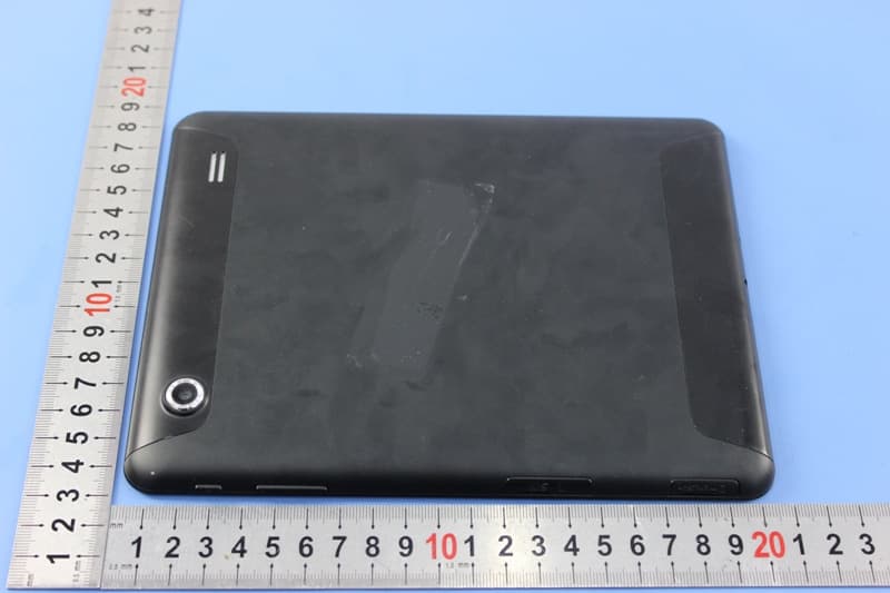
Click to zoom
Application Details
- Equipment Class
- PCB - PCS Licensed Transmitter
- Date of Grant
- Dec 27, 2014
- Application Purpose
- Original Equipment
- Date of Application
- Dec 25, 2014
- Equipment Note
- Eviant 8 3G
- Frequency Range
- 1852.40000000 - 1907.60000000
- Country
- United States
Documents & Files
Document Text
Text extracted from the exhibit documents filed with the FCC. Open a document above to read the original.
Users Manual
- 1 - Contents Chapter 1 Quick Start ....................................................................................... - 2 - 1.1 Appearance Introduction ...................................................................... - 2 - 1.2 Attachment ............................................................................................... - 3 - 1.3 SIM & SD card Installation .................................................................... - 3 - 1.4 Charging .................................................................................................... - 5 - 1.5 Turning On/Off ......................................................................................... - 6 - Chapter 2 Basic Operation ................................................................................. - 7 - 2.1 Home Screen ............................................................................................ - 7 - 2.2 Volumes ..................................................................................................... - 9 - Chapter 3 E-mail ................................................................................................... - 9 - 3.1 Google Account ...................................................................................... - 9 - 3.2 Gmail ........................................................................................................ - 10 - 3.3 E-mail ....................................................................................................... - 11 - Chapter 4 Network and Browser .................................................................... - 13 - 4.1 Mobile Networks ................................................................................... - 13 - 4.2 Browser ................................................................................................... - 13 - Chapter 5 BT ........................................................................................................ - 14 - 5.1 Using BT ................................................................................................. - 14 - Chapter 6 Multimedia ........................................................................................ - 14 - 6.1 Camera .................................................................................................... - 14 - 6.2 Photo Options ....................................................................................... - 15 - 6.3 Camcorder .............................................................................................. - 19 - 6.4 Sound Recorder .................................................................................... - 21 - Chapter 7 USB & Micro SD card ..................................................................... - 21 - 7.1 USB connection .................................................................................... - 21 - 7.2 Micro SD card ........................................................................................ - 22 - - 3 - 1.2 Attachment Your packing box comprises the following attachments Tablet USB cable Charger 1.3 SIM & SD card Installation SIM ·SIM card Installation Locate the SIM card slot,insert the SIM as picture below: - 4 - ·SIM card Removal To remove the SIM card, please turn off the tablet first ,or else the SIM card can become damaged. Micro SD card Micro SD cards are used to store photos, music, video and other data. ·Micro SD card Installation Locate the Micro SD card slot, insert the Micro SD card as picture below: - 5 - ·Micro SD card Removal 1. Please make sure to disconnect the SD card from the tablet. Click >Settings>Storage>Unmount SD card 2. Open the Micro SD card protection cover. 3. Use your fingertips to push the Micro SD card, the Micro SD card will then eject from the slot. 1.4Charging Charging When the battery is charging, the icon appears in the status bar. When the battery is fully charged, the icon appears in the status bar. Connect the charger to the tablet using the USB/charger cable.Thecable - 6 - plugs into the USB/charger port at the bottom: 1.5Turning On/Off Turning On Press and hold power key to turn on the tablet,it will take about 30 seconds to completely boot-up. Turning Off Press and hold power key ,and a menu will appear. Choose Power off and select OK when it appears. - 7 - Standby 1. The tablet will automatically enter sleep mode after 10 seconds of inactivity by default. Screen timeout time can be changed. 2. Wake up the tablet from standby mode by pressing . Chapter 2 Basic Operation 2.1 Home Screen You can switch between the various home screens by swiping left and right The main key ·Menu :Opens the application drawer. ·Google Search :Use this to quickly access the Google search services. ·The home key :Go to the home screen. ·Back key :Return to the previous screen. ·Task Switch key : Opens all recently used applications. Applications can also be closed by swiping to the right on the application you wantto close. Status Bar Status bar will display various important status information. Swipe up from the bottom of the status menu to close the status bar. - 8 - IconExplainIconExplain SIM card not detected Signal strength On 3G NetworkOn GSM Network OnEDGE Network Airplane mode ChargingLow power Full powerSilent mode Vibration modeAlarm set GPS on USB is connected Shortcuts To customize different home screen, you can add and reposition various app shortcuts. Click to open the application drawer.long press and drag the APP you wish to add to the home screen.You can always reposition the variousapp shortcuts home screen by long pressing and dragging. Widgets You can add a clock, music player and calendar widgets on the main screen. Click to open the application drawer,then choose long press any widget to drag it to the screen of your choosing. Wallpapers There are two methods for changing the wallpaper of your tablet 1.Touch and hold an empty area on the home screen. - 9 - Choose “Gallery” to use your ow…
Text truncated - open the document above for the full version.
Cover Letter(s)
Vicky Yuan
External Photos
1 Photographs - EUT Constructional Details Test model No.: EVC8Q
Internal Photos
1 Photographs - EUT Constructional Details Test model No.: EVC8Q
Parts List/Tune Up Info
UNION INFORMATION TECHNOLOGIES (USA) INC Tune up procedure The output power setting of EUT is set in the factory and followed the max average level in below. There is no tune up procedure except factory default setting. GSM850 GPRS (GMSK): 1 TX Slot: 31dBm (-1.5~1.5) dB 2 TX Slots: 31dBm (-1.5~1.5) dB 3 TX Slots: 31dBm (-1.5~1.5) dB 4 TX Slots: 31dBm (-1.5~1.5) dB EGPRS (GMSK): 1 TX Slot: 31dBm (-1.5~1.5) dB 2 TX Slots: 31dBm (-1.5~1.5) dB 3 TX Slots: 31dBm (-1.5~1.5) dB 4 TX Slots: 31dBm (-1.5~1.5) dB EGPRS (8PSK): 1 TX Slot: 24dBm (-1.5~1.5) dB 2 TX Slots: 24dBm (-1.5~1.5) dB 3 TX Slots: 24dBm (-1.5~1.5) dB 4 TX Slots: 24dBm (-1.5~1.5) dB GSM1900 GPRS (GMSK): 1 TX Slot: 29dBm (-1.5~1.5) dB 2 TX Slots: 29dBm (-1.5~1.5) dB 3 TX Slots: 28dBm (-1.5~1.5) dB 4 TX Slots: 28dBm (-1.5~1.5) dB EGPRS (GMSK): 1 TX Slot: 29dBm (-1.5~1.5) dB 2 TX Slots: 29dBm (-1.5~1.5) dB 3 TX Slots: 28dBm (-1.5~1.5) dB 4 TX Slots: 28dBm (-1.5~1.5) dB EGPRS (8PSK): 1 TX Slot: 24dBm (-1.5~1.5) dB 2 TX Slots: 24dBm (-1.5~1.5) dB 3 TX Slots: 24dBm (-1.5~1.5) dB 4 TX Slots: 24dBm (-1.5~1.5) dB WCDMA850 WCDMA: 23dBm (-1.5~1.5) dB HSDPA: 22dBm (-1.5~1.5) dB HSUPA: 21dBm (-1.5~1.5) dB WCDMA 1900 WCDMA: 24dBm (-1.5~1.5) dB HSDPA: 23dBm (-1.5~1.5) dB HSUPA: 22dBm (-1.5~1.5) Db BT: BT 2.0: 0.5dBm (-1.5~1.5) dB BLE: 1.5dBm (-1.5~1.5) dB WIFI: 802.11b: 16dBm(-2~2)dB 802.11g: 15dBm(-1.5~1.5) dB 802.11n (HT20): 13dBm(-1.5~1.5) dB 802.11n (HT40): 13dBm(-2~2) dB
RF Exposure Info
Calibration Laboratory of Schmid & Partner Eng ineering AG Zeughausstrasse 43,8004 Zurích,Swítzerland 、、可叩1"/’?轧 关注~;~乞 二F Z画~.~".",A= -EOft2些-'r.! -:.~今尹乓?毛主 ’'1~I//飞\沪i 吨1/,,1,,\、、I SSchweízeríscher Kalíb巾rdíenst c s Servíce suísse d'étalonnage Servízío svízzero dítaratura Swíss Calíbratíon Servíce Accredited bythe Swiss Accreditation Service(SAS) The Swíss Accreditation Service is one ofthe signatories to the EA Multílateral Agreement for the recognítion of calíbration certificates Accreditatíon No.:SCS 108 Clíent SGS-SZ (Auden) 臼而饲饵teNo:Dl900V2-5d028~Nov13 CALIBRATION CERTIFICATE Objecl D1900V2 - SN: 5d028 Calibration procedure(s) QA CAL-05.v9 Calibration procedure for dipole validation kits above 700 MHz Calibration date November 2.7,_201~. This calibration ce同ificate documents the traceability to national standards,which realize the physical units of measurements (SI). The measurements and the uncertainties with confidence probability are givenon the following pages and arepart of the certificate. AIIcalibrations have beenconductedin the closed laboratoryfacility:environment temperature(22:f:3)OCand humidity<70%. Calibration Equipment used(M&TEcriticalfor calibration) Primary StandardsID#Cal Date (Certificate No.) Power meter EPM-442AGB3748070409-0ct-13 (No.217-01827) Powersensor HP 8481AUS3729278309-0ct-13(No. 217-01827) Power sensorHP 8481 AMY4109231709-0ct-13 (No.217-01828) Reference20 dB AttenuatorSN: 5058 (20k)04-Apr-13(No. 217-01736) Type-N mismatchcombination SN:5047.3/0632704-Apr-13 (No.217-01739) Reference Probe ES3DV3SN: 3205 28-Dec-12 (No.ES3-3205_Dec12) DAE4SN: 60125-Apr-13 (No.DAE4-60LApr13) Secondary Standard~ ID#Check Date(in house) RF generatorR&S SMT-06100005 04-Aug-99 (in house check Oct-13) Network Analyzer HP8753E US37390585 8420618-0ct-01 (in housecheck Oct-13) Scheduled Calibration Oct-14 Oct-14 Oct-14 Apr-14 Apr-14 Dec-13 Apr-14 ScheduledCheck In house check:Oct-15 In h。也Jsecheck:Oct-14 Calibratedby: Name JetonKastrati Function LaboratoryTechnician Signature Approved by: Katja Pokovíc TechnicalManager Issued:November27, 2013 This calibrationcertificate shall not bereproduced except in full without written approvalof the laboratory CertificateNo: D1900V2-5d028_Nov13 Page 1 of 8 Calibration Laborat。叩。f Schmid&Partner Engineering AG Zeughausstrasse43,8004Zurich,Switzerland 、、刊巳.t:'/,z 二二守主二二4毛 二 二哥~二..-r-a:: ::II.~田‘’~幅画忌- 亏二元杀气卢 -"1",:.1,;'、y S Schweize巾cherKalibrierdienst c s Servicesuissed'étalonnage Serviziosvizzeroditaratura SwissCalibrationService AccreditedbytheSwissAccreditationService(SAS) TheSwissAccreditationServiceisoneofthesignatoriestotheEA MultilateralAgreementfortherecognitionofcalibrationcertificates AccreditationNo.:SCS 108 Glossary: TSL ConvF N/A tissue simulating liquid sensitivity in TSL/ NORM x,y,z not applicable or not measured Calibration is Performed According to the Following Standards: a) IEEE Std 1528-2013,“I EEE Recommended Practice for Determining the Peak Spatial Averaged Specific Absorption Rate (SAR) in the Human Head from Wireless Communications Devices: Measurement Techniques",June 2013 b) IEC 62209-1, "Procedure to measure the Specific Absorption Rate (SAR) for hand-held devices used in close proximity to the ear (frequency range of 300 MHz to 3 GHZ)", Februa叩2005 c) KDB 865664,“SAR Measurement Requirements for 100 MHz to 6 GHz" Additional Documentation: d) DASY4/5 System Handbook Methods Applied and Interpretation of Parameters: • Measurement Conditions:Further details are available from the Validation Repo同at the end of the certificate.AII figures stated in the certificate are valid at the frequency indicated. • Antenna Parameters with TSL:The dipole is mounted with the spacer to position its feed point exactly below the center marking of the flat phantom section,with the arms oriented parallel to the body axis. • Feed Point Impedance and Return Loss:These parameters are measured with the dipole positioned under the liquid filled phantom. The impedance statedis transformed from the measurement at the SMA connector to the feed point.The Return Loss ensures low reflected power. No uncertainty required. • Electrical Oelay:One-way delay between the SMA connectorand the antenna feed point. No uncertainty required. • SAR measured:SAR measured at the stated antenna input power. • SAR normalized:SAR as measured,normalized to an input power of 1 W at the antenna connector. • SAR for nominal TSLparameters:The measured TSL parametersare used to calculate the nominal SAR result. The reported uncertainty of measurement is stated as the standard uncertainty ofmeasurement multiplied by thecoverage factor k=2,which for a normal distribution corresponds to a coverage probability of approximately 95%. CertificateNo: D1900V2-5d028Nov13 page2 of8 Measurement Conditions Qt.SYsystem configu uratlon,as tar as not givenon page1. DASY Version DASY5 V52.8.7 Extrapolation Advanced Extrapolation Phantom Modular FlatPhantom Distance Dipole Center - TSL 10 mm with Spacer Zoom Scan Resolution dx, dy, dz = 5 mm Frequency 1900 MHz士1MHz HeadTSL parameters The foll ’主,干干?二一’一_--...-............-,...,.............. TemperaturePermi忧ivityConductivity Nominal Head TSL parameters 22.00C 40.0 1.40 mho/m Measured Head TSL parameters(22.0:t0.2) oC 39.8土6% 1.39 mho/m:t6 % Head TSL temperature change during test <0.5 oC ---- ---- SARresult with HeadTSL SAR averaged over 1 cm3(1 g) of Head TSL SAR measured SAR for nominalHead TSL parameters 响 - w r 、 - 4 , n v - n I I - o o - 川 - t u 山 - P - d A U - n H - 咀 A n H E - - , - n M - o - N E 创 E E 刑 m o ω 民 M 「 210.2 W/kg 40.9 W/kg主17.0% (k=2) SAR averaged over 10 cm3(10 g) of Head TSL SAR measured SAR for nominalHead TSL parameters condition 250 mW input power normalizedto 1W 5.33 W/kg 21.4 W/kg土16.5% (k=2) Body TSL parameters The followinaoarameters and calculati Temperature Permi忧ivityConductivity Nominal Body TSL parameters22.0oC 53.3 1.52 mho/m Measured Body TSL parameters (22.0:t0.2) oC53.4:t6 % 1.51 mho/m:t6 % Body…
Text truncated - open the document above for the full version.
Test Report
SGS-CSTC Standards Technical Services Ltd. No. 1 W orkshop, M-10, Middle section, Science & Technology Park, Nanshan District, Shenzhen, Guangdong, China 518057 Telephone: +86 (0) 755 2601 2053 Fax: +86 (0) 755 2671 0594 Email: [email protected] Report No.: SZEM140900494504 Page: 1 of 85 Authorized Signature: Jack Zhang EMC Laboratory Manager The manufacturer should ensure that all products in series production are in conformity with the product sample detailed in this report. If the product in this report is used in any configuration other than that detailed in the report, the manufacturer must ensure the new system complies with all relevant standards. Any mention of SGS International Electrical Approvals or testing done by SGS International Electrical Approvals in connection with, distribution or use of the product described in this report must be approved by SGS International Electrical Approvals in writing. The report must not be used by the client to claim product certification, approval, or endorsement by NVLAP, NIST, or any agency of the federal government. All test results in this report can be traceable to National or International Standards. “This document is issued by the Company subject to its General Conditions of Service printed overleaf, available on request or accessible at www.sgs.com/terms_and_conditions.htm and, for electronic format documents, subject to Terms and Conditions for Electronic Documents at www.sgs.com/terms_e-document.htm. Attention is drawn to the limitation of liability, indemnification and jurisdiction issues defined therein. Any holder of this document is advised that information contained hereon reflects the Company’s findings at the time of its intervention only and within the limits of Client’s instructions, if any. The Company’s sole responsibility is to its Client and this document does not exonerate parties to a transaction from exercising all their rights and obligations under the transaction documents. This document cannot be reproduced except in full, without prior written approval of the Company. Any unauthorized alteration, forgery or falsification of the content or appearance of this document is unlawful and offenders may be prosecuted to the fullest extent of the law. Unless otherwise stated the results shown in this test report refer only to the sample(s) tested and such sample(s) are retained for 90 days only.” Appendix for Test Report SGS-CSTC Standards Technical Services Ltd. Report No.: SZEM140900494504 Page: 2 of 85 “This document is issued by the Company subject to its General Conditions of Service printed overleaf, available on request or accessible at www.sgs.com/terms_and_conditions.htm and, for electronic format documents, subject to Terms and Conditions for Electronic Documents at www.sgs.com/terms_e-document.htm. Attention is drawn to the limitation of liability, indemnification and jurisdiction issues defined therein. Any holder of this document is advised that information contained hereon reflects the Company’s findings at the time of its intervention only and within the limits of Client’s instructions, if any. The Company’s sole responsibility is to its Client and this document does not exonerate parties to a transaction from exercising all their rights and obligations under the transaction documents. This document cannot be reproduced except in full, without prior written approval of the Company. Any unauthorized alteration, forgery or falsification of the content or appearance of this document is unlawful and offenders may be prosecuted to the fullest extent of the law. Unless otherwise stated the results shown in this test report refer only to the sample(s) tested and such sample(s) are retained for 90 days only.” CONTENT APPENDIX FOR TEST REPORT ........................................................................................................1 1 APPENDIX_A: EFFECTIVE (ISOTROPIC) RADIATED POWER OUTPUT DATA .......................4 PART I - TEST RESULTS ..................................................................................................................4 2 APPENDIX_B: PEAK-TO-AVERAGE RATIO ..............................................................................6 PART I - TEST RESULTS ..................................................................................................................6 3 APPENDIX_C: MODULATION CHARACTERISTICS ..................................................................7 PART I - TEST PLOTS .......................................................................................................................7 3.1 FOR GSM .............................................................................................................................7 3.1.1 TEST BAND = GSM850 .................................................................................................7 3.1.2 TEST BAND = GSM1900 ...............................................................................................9 3.2 FOR UMTS ......................................................................................................................... 11 3.2.1 TEST BAND = WCDMA850 ......................................................................................... 11 3.2.2 TEST BAND = WCDMA1900 ....................................................................................... 12 4 APPENDIX_D: BANDWIDTH .................................................................................................... 13 4.1.1 TEST BAND = GSM850 ............................................................................................... 14 4.1.2 TEST BAND = GSM1900 ............................................................................................. 20 4.2 FOR UMTS ......................................................................................................................... 26 4.2.1 TEST BAND = WCDMA850 ..........................................................................…
Text truncated - open the document above for the full version.
Test Report
SGS-CSTC Standards Technical Services Ltd. No. 1 W orkshop, M-10, Middle section, Science & Technology Park, Nanshan District, Shenzhen, Guangdong, China 518057 Telephone: +86 (0) 755 2601 2053 Fax: +86 (0) 755 2671 0594 Email: [email protected] Report No.: SZEM140900494504 Page: 1 of 26 Authorized Signature: Jack Zhang EMC Laboratory Manager The manufacturer should ensure that all products in series production are in conformity with the product sample detailed in this report. If the product in this report is used in any configuration other than that detailed in the report, the manufacturer must ensure the new system complies with all relevant standards. Any mention of SGS International Electrical Approvals or testing done by SGS International Electrical Approvals in connection with, distribution or use of the product described in this report must be approved by SGS International Electrical Approvals in writing. The report must not be used by the client to claim product certification, approval, or endorsement by NVLAP, NIST, or any agency of the federal government. All test results in this report can be traceable to National or International Standards. “This document is issued by the Company subject to its General Conditions of Service printed overleaf, available on request or accessible at www.sgs.com/terms_and_conditions.htm and, for electronic format documents, subject to Terms and Conditions for Electronic Documents at www.sgs.com/terms_e-document.htm . Attention is drawn to the limitation of liability, indemnification and jurisdiction issues defined therein. Any holder of this document is advised that information contained hereon reflects the Company’s findings at the time of its intervention only and within the limits of Client’s instructions, if any. The Company’s sole responsibility is to its Client and this document does not exonerate parties to a transaction from exercising all their rights and obligations under the transaction documents. This document cannot be reproduced except in full, without prior written approval of the Company. Any unauthorized alteration, forgery or falsification of the content or appearance of this document is unlawful and offenders may be prosecuted to the fullest extent of the law. Unless otherwise stated the results shown in this test report refer only to the sample(s) tested and such sample(s) are retained for 90 days only.” 1 Cover page FCC RF TEST REPORT Application No: SZEM1409004945RF Applicant: UNION INFORMATION TECHNOLOGIES (USA) INC Manufacturer/ Factory: Shenzhen ACT Industrial Co., Ltd. Product Name: Eviant 8 3G Mode No.(EUT): EVC8Q Trade Mark: EVIANT FCC ID: 2AC7GEVC8Q Standards: 47 CFR Part 2(2013) 47 CFR Part 22 subpart H(2013) 47 CFR Part 24 subpart E(2013) Test Method: FCC KDB 971168 D01 Power Meas License Digital Systems v02r01 NOTE: In the configuration tested, the EUT complied with the standards specified above. SGS-CSTC Standards Technical Services Ltd. Report No.: SZEM140900494504 Page: 2 of 26 “This document is issued by the Company subject to its General Conditions of Service printed overleaf, available on request or accessible at www.sgs.com/terms_and_conditions.htm and, for electronic format documents, subject to Terms and Conditions for Electronic Documents at www.sgs.com/terms_e-document.htm. Attention is drawn to the limitation of liability, indemnification and jurisdiction issues defined therein. Any holder of this document is advised that information contained hereon reflects the Company’s findings at the time of its intervention only and within the limits of Client’s instructions, if any. The Company’s sole responsibility is to its Client and this document does not exonerate parties to a transaction from exercising all their rights and obligations under the transaction documents. This document cannot be reproduced except in full, without prior written approval of the Company. Any unauthorized alteration, forgery or falsification of the content or appearance of this document is unlawful and offenders may be prosecuted to the fullest extent of the law. Unless otherwise stated the results shown in this test report refer only to the sample(s) tested and such sample(s) are retained for 90 days only.” 2 Notice 2.1 Test Facility The test facility is recognized, certified, or accredited by the following organizations: • CNAS (No. CNAS L2929) CNAS has accredited SGS-CSTC Standards Technical Services Co., Ltd. Shenzhen Branch EMC Lab to ISO/IEC 17025:2005 General Requirements for the Competence of Testing and Calibration Laboratories (CNAS-CL01 Accreditation Criteria for the Competence of Testing and Calibration Laboratories) for the competence in the field of testing. • VCCI The 10m Semi-anechoic chamber and Shielded Room (7.5m x 4.0m x 3.0m) of SGS- CSTC Standards Technical Services Co., Ltd. have been registered in accordance with the Regulations for Voluntary Control Measures with Registration No.: G-823, R-4188, T-1153 and C-2383 respectively. • FCC – Registration No.: 556682 SGS-CSTC Standards Technical Services Co., Ltd., Shenzhen EMC Laboratory has been registered and fully described in a report filed with the (FCC) Federal Communications Commission. The acceptance letter from the FCC is maintained in our files. Registration No.: 556682. • Industry Canada (IC) Two 3m Semi-anechoic chambers of SGS-CSTC Standards Technical Services Co., Ltd. have been registered by Certification and Engineering Bureau of Industry Canada for radio equipment testing with Registration No.: 4620C-1 & 4620C-2. 2.2 Deviation from Standards None. 2.3 Abnormalities from Standard Conditions None. 2.4 Other Information Requested by the Customer None. SGS-CSTC Standards Technical Services Ltd. Report No.: SZEM140900494504 Page: 3 of 26 “This document is issued by the Company subject to its General Conditions of Service printed overleaf, available on request or accessible at www.sgs.com/terms_and_conditions.htm and, for electronic format documents, s…
Text truncated - open the document above for the full version.
Test Setup Photos
1 Photographs - EUT Test Setup Test model No.: EVC8Q 1.1 Conducted Emission 1.2 Radiated Emission 1.3 Radiated Spurious Emission
Contact Information
Applicant
Bo Qiu(general manager)
Technical Contact
SGS-CSTC Standards Technical ServicesLtdEmen Li
[email protected]0755-2654 4119
No.1 Workshop, M-10, Middle Section, · Shenzhen · China
Non-Technical Contact
SGS-CSTC Standards Technical ServicesLtdVicky Yuan
[email protected]0755-25328517
Test Firm
SGS-CSTC Standards Technical Services Co.,Ltd.June Zhang
Technical Specifications
| # | Rule Parts | Frequency Range | Power Output | Emission | Tolerance |
|---|---|---|---|---|---|
| 6 | 24E | 1.85 GHz - 1.91 GHz | 388.20 mW | 4M75F9W | 0.1 ppm |
Other Applications from UNION INFORMATION TECHNOLOGIES (USA) INC
2AC7GEVT10Q
Dec 08, 2014Eviant 10 3G
Equipment Class
DSS - Part 15 Spread Spectrum Transmitter