Text extracted from the exhibit documents filed with the FCC. Open a document above to read the original.
QUICK SETUP GUIDE IP CAMERA BEFORE YOU GET STARTED YOU WILL NEED Images used are for reference only. Your product may vary slightly. Please visit our website at www.NightOwlSP.com for all manuals, software, and firmware updates. There are also How-To videos with step-by-step instructions for connecting your camera. 4 2 1 3 5 INSTALLATION PROCESS CameraPower AdapterUSB-to-Micro USBMounting Strip Peel to expose adhesive ShelfWallWindow CONNECTING TO THE NIGHT OWL APP DeviceLiveViewPlaybackSettingsMore Edit device manager Add NVR-7P Device DVR Add Add device Owl Scan/Manual Wireless Cancel Select a method of adding device FCC Statement Warning: Changes or modifications to this unit not expressly approved by the party responsible for compliance could void the user’s authority to operate the equipment. NOTE: This equipment has been tested and found to comply with the limits for a Class B digital device, pursuant to Part 15 of the FCC Rules. These limits are designed to provide reasonable protection against harmful interference in a residential installation. This equipment generates, uses and can radiate radio frequency energy and, if not installed and used in accordance with the instructions, may cause harmful interference to radio communications. However, there is no guarantee that interference will not occur in a particular installation. If this equipment does cause harmful interference to radio or television reception, which can be determined by turning the equipment off and on, the user is encouraged to try to correct the interference by one or more of the following measures: Reorient or relocate the receiving antenna. Increase the separation between the equipment and receiver. Connect the equipment into an outlet on a circuit different from that to which the receiver is connected. Consult the dealer or an experienced radio/TV technician for help. FCC RF Radiation Exposure Statement Caution: To maintain compliance with the FCC’s RF exposure guidelines, place the product at least 20cm from nearby persons.
Model: CAM-IP-HDW FCC ID: 2AC7RCAMIPC07 This device complies with Part 15 of the FCC Rules. Operation is subject to the following two conditions: (1) This device may not cause harmful interference, and (2) this device must accept any interference received, including interference that may cause undesired operation. Made in china Label Size: 27*10mm
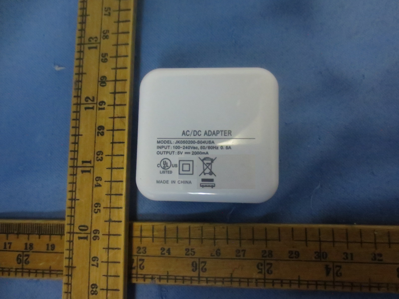
1 INTERTEK TESTING SERVICES RF Exposure The equipment under test (EUT) is a WIRELESS IP CAMERA. The EUT was powered by AC/DC adapter with input of 100-240Vac, 50/60Hz, 0.5A and output of 5Vdc, 2000mA. For more detail information pls. refer to the user manual. For WIFI function: Antenna Type: Integral Antenna Antenna Gain: 3dBi Modulation Type: BPSK, QPSK, 16QAM, 64QAM, CCK, DQPSK, DBPSK. The nominal conducted output power specified: 14dBm +/-3dB. According to the KDB 447498: The maximum peak conducted output power of WiFi function is 14.0dBm in the frequency 2462MHz (802.11b) which is within the product variation. The minimum peak conducted output power of WiFi function is 12.3dBm in the frequency 2422MHz (802.11 n-HT40) which is within the production variation. According to FCC Part 2.1091, this unlicensed transmitting devices is categorically excluded from routine environmental evaluation for RF exposure prior to equipment authorization or use, According to the KDB 447498 and OET 65, the simple calculation as below: S (power density) = PG/4πR^2 For Maximum Permissible Exposure (MPE) evaluation of the product, the maximum power density at 20 cm from this transmitter shall be less than the General Population / Uncontrolled MPE limit in FCC Part 1.1310. PG = The maximum conducted output power + Antenna Gain = 20dBm = 100mW From above data, the exposed power density at a distance (R) of 20cm from the center of radiation of the antenna can be calculated according to KDB447498as follow: = 100mW / 4πR^2 = 0.0199 mW/cm^2 The MPE limit is 1.0 mWcm-2 for general population and uncontrolled exposure in the WiFi frequency range according to FCC Part 1.1310. As the measured power density at 20cm from the transmitter is lower than the MPE limit, the compliance to the MPE limit can be ensured by indicating the minimum 20cm separation between the transmitter's radiating structure and body of the user or nearby persons. FCC ID: 2AC7RCAMIPC07 FCC ID: 2$&75&$0,3&07 2 INTERTEK TESTING SERVICES For Bluetooth Function: Modulation Type: GFSK Bluetooth Version: 4.0 (Single Mode) Antenna Type: Integral antenna Antenna Gain: 2dBi The nominal radiated output power (e.i.r.p) specified: 1.0 dBm (tolerance: +/- 3 dB) The nominal conducted output power specified: -1.0 dBm (tolerance: +/- 3dB) According to the KDB 447498: The maximum radiated emission of the BT4.0 function is 97.5dBμV/m at 3m in the frequency 2.480GHz = [(FS*D) ^2 / 30] mW = 2.27dBm which is within the production variation. The minimum radiated emission of the BT4.0 function is 96.5dBμV/m at 3m in the frequency 2.442GHz = [(FS*D) ^2 / 30] mW = 1.27dBm which is within the production variation. According to FCC Part 2.1091, this unlicensed transmitting devices is categorically excluded from routine environmental evaluation for RF exposure prior to equipment authorization or use, from the KDB 447498 and OET 65, the simple calculation as below: S (power density) = PG/4πR^2 For Maximum Permissible Exposure (MPE) evaluation of the product, the maximum power density at 20 cm from this transmitter shall be less than the General Population / Uncontrolled MPE limit in FCC Part 1.1310. PG = The maximum conducted output power + Antenna Gain = 4dBm = 2.51mW From above data, the exposed power density at a distance (R) of 20cm from the center of radiation of the antenna can be calculated according to KDB447498 as follow: = 2.51mW / 4πR^2 = 0.0005 mW/cm^2 The MPE limit is 1.0 mWcm-2 for general population and uncontrolled exposure in the WiFi frequency range according to FCC Part 1.1310. As the measured power density at 20cm from the transmitter is lower than the MPE limit, the compliance to the MPE limit can be ensured by indicating the minimum 20cm separation between the transmitter's radiating structure and body of the user or nearby persons. FCC ID: 2AC7RCAMIPC07 3 RF Exposures Evaluation for simultaneous transmission The EUT including Bluetooth and WIFI transceiver whitch can transmmit simultaneously The specification of Bluetooth 4.0 and WiFi as below: Ant1 Gain: 3.0dBi for WIFI; Ant2 Gain: 2.0dBi for Bluetooth For WIFI nominal conducted output power specified: 14dBm (Tolerance: ±3dBm) For Bluetooth nominal conducted output power specified: -1dBm (Tolerance: ±3dBm) The KDB 447498: A Mobile Multi-transmitter MPE Estimation MPE spreadsheet is used for estimating MPE limits for these 2 transmitter's simultaneous transmission. The information of operating frequency (MHz), power (W), antenna gain (dBi), location (X and Y coordinates showed on next page) for each antenna are entered in the MPE Spreadsheet. The power densities of up to 2 antennas located within a 90 cm² region at 1cm intervals are estimated first. Then the power densities computed for each antenna are summed. The plot “% MPE Contour” displays the result in percentages of the frequency-dependent power density limits. As the measured power density at 20cm from the transmitter is lower than the MPE limit (the compliance boundary for simultaneous transmission), the compliance to the MPE limit can be ensured by indicating the minimum 20cm separation between the transmitter’s radiating structures and body of the user or nearby persons. RF Radiation Exposure Statement Caution as below should be put in the manual: To maintain compliance with the FCC’s RF exposure guidelines, place the product at least 20cm from nearby persons. FCC ID: 2AC7RCAMIPC07 4 Ant 1 X, Y (5, 1) Ant 2 X, Y (0, 0) FCC ID: 2AC7RCAMIPC07 5 Antenna No. T o tal 1 2 3 4 5 6 Tx Status On On Off Off Off Off Frequency MHz 2450 2450 1900 2450 2450 5800 MPE Limit mW/cm 2 1.00 1.00 0.00 0.00 0.00 0.00 Max % MPE % 2.0 2.0 0.1 0.0 0.0 0.0 0.0 Power (W) 0.052 0.050 0.002 0.000 0.000 0.000 0.000 Antenna Gain dBi 3.00 2.00 3.00 1.50 0.50 1.00 EIRP (W) 0.10 0.100 0.003 0.000 0.000 0.000 0.000 X (cm) 5.0 0.0 12.0 4.0 -8.0 8.0 Y (cm) 1.0 0.0 0.0 0.0 0.0 0.0 Sector FALSE FALSE FALSE FALSE FALSE FALSE Arc FALSE FALSE FALSE FALSE FALSE FALSE θ 1 degs input -…
Text truncated - open the document above for the full version.
• The test results reported in this test report shall refer only to the sample actually tested and shall not refer or be deemed to refer to bulk from which such a sample may be said to have been obtained. • This report is for the exclusive use of Intertek's Client and is provided pursuant to the agreement between Intertek and its Client. Intertek's responsibility and liability are limited to the terms and conditions of the agreement. Intertek assumes no liability to any party, other than to the Client in accordance with the agreement, for any loss, expense or damage occasioned by the use of this report. Only the Client is authorized to copy or distribute this report. Any use of the Intertek name or one of its marks for the sale or advertisement of the tested material, product or service must first be approved in writing by Intertek. The observations and test results referenced from this report are relevant only to the sample tested. This report by itself does not imply that the material, product, or service is or has ever been under an Intertek certification program. • For Terms And Conditions of the services, it can be provided upon request. • The evaluation data of the report will be kept for 3 years from the date of issuance. TRF no.: FCC 15C_Tx_b Intertek Testing Services Shenzhen Ltd. Kejiyuan Branch 6F, D Block, Huahan Building, Langshan Road, Nanshan District, Shenzhen, P. R. China Tel: (86 755) 8601 6288 Fax: (86 755) 8601 6751 Website: www.china.intertek-etlsemko.com Henan Taide Electronic Technology Co., Ltd. Application For Certification FCC ID: 2AC7RCAMIPC07 Wireless IP Camera Model: CAM-IP-HDW WiFi Transceiver Report No.: 140909021SZN-001 We hereby certify that the sample of the above item is considered to comply with the requirements of FCC Part 15, Subpart C for Intentional Radiator, mention 47 CFR [ 10-1-13] Prepared and Checked by: Approved by: Sign on file Robert Li Project Engineer Andy Yan Senior Project Engineer Date: October 27, 2014 INTERTEK TESTING SERVICE TRF no.: FCC 15C_TX_b FCC ID: 2AC7RCAMIPC07 Report No.: 140909021SZN-001 i LIST OF EXHIBITS INTRODUCTION EXHIBIT 1: Summary of Tests EXHIBIT 2: General Description EXHIBIT 3: System Test Configuration EXHIBIT 4: Measurement Results EXHIBIT 5: Equipment Photographs EXHIBIT 6: Product Labeling EXHIBIT 7: Technical Specifications EXHIBIT 8: Instruction Manual EXHIBIT 9: Confidentiality Request EXHIBIT 10: Miscellaneous Information EXHIBIT 11: Test Equipment List INTERTEK TESTING SERVICES TRF no.: FCC 15C_TX_b FCC ID: 2AC7RCAMIPC07 Report No.: 140909021SZN-001 ii MEASUREMENT/TECHNICAL REPORT Wireless IP Camera Model: CAM-IP-HDW FCC ID: 2AC7RCAMIPC07 This report concerns (check one) Original Grant X Class II Change Equipment Type: DTS - Part 15 Digital Transmission Systems (WiFi transmitter portion) Deferred grant requested per 47 CFR 0.457(d)(1)(ii)? Yes No X If yes, defer until : date Company Name agrees to notify the Commission by: date of the intended date of announcement of the product so that the grant can be issued on that date. Transition Rules Request per 15.37? Yes No X If no, assumed Part 15, Subpart C for intentional radiator - the new 47 CFR [10-01-13] Edition] provision. Report prepared by: Robert Li Intertek Testing Services Shenzhen Ltd. Kejiyuan Branch 6F, Block D, Huahan Building, Langshan Road, Nanshan District, Shenzhen, P. R. China Phone: (86 755) 8614 0657 Fax: (86 755) 8614 6751 INTERTEK TESTING SERVICES TRF no.: FCC 15C_TX_b FCC ID: 2AC7RCAMIPC07 Report No.: 140909021SZN-001 iii Table of Contents 1.0 Summary of test results ............................................................................... 2 2.0 General Description ................................................................................................ 4 2.1 Product Description ....................................................................................... 4 2.2 Related Submittal(s) Grants .......................................................................... 5 2.3 Test Methodology .......................................................................................... 5 2.4 Test Facility ................................................................................................... 5 3.0 System Test Configuration ................................................................................. 7 3.1 Justification ................................................................................................... 7 3.2 EUT Exercising Software ............................................................................... 7 3.3 Details of EUT and Description of Peripherals ............................................... 7 3.4 Measurement Uncertainty.............................................................................. 8 3.5 Equipment Modification ................................................................................. 8 3.6 Support Equipment List and Description ...................................................... 8 4.0 Measurement Results .......................................................................................... 10 4.1 Maximum Conducted Output Power at Antenna Terminals .......................... 10 4.2 Minimum 6dB RF Bandwidth ....................................................................... 12 4.3 Maximum Power Density ................................................................................ 22 4.4 Out of Band Conducted Emissions ............................................................... 31 4.5 Out of Band Radiated Emissions ................................................................. 44 4.6 Transmitter Radiated Emissions in Restricted Bands ................................... 45 4.7 Field Strength Calculation ............................................................................ 46 4.8 Radiated Spurious Emission ........................................................................... 47 4.9 Conducted Emission ............................…
Text truncated - open the document above for the full version.
Date: 21.OCT.2014 14:08:34 Date: 21.OCT.2014 14:16:24
Date: 21.OCT.2014 14:11:43 Date: 21.OCT.2014 14:18:25
6F, D Block, Huahan Building, Langshan Road · Shenzhen · China
| # | Rule Parts | Frequency Range | Power Output |
|---|---|---|---|
| 1 | 15C | 2.41 GHz - 2.46 GHz | 25.00 mW |

IP Pan and Tilt Wireless Camera
Equipment Class
DTS - Digital Transmission System