FCCID.CO- FCC ID Database
HomeCompaniesEquipment ClassesSearch

© 2026 FCC ID Database. All rights reserved.

AboutContactData sourced from FCC public records
  1. Home/
  2. Henan Taide Electronic Technology CO., LTD/
  3. 2AC7RCAMIPPT08

2AC7RCAMIPPT08IP Pan and Tilt Wireless Camera

Henan Taide Electronic Technology CO., LTD
IP Pan and Tilt Wireless Camera - FCC ID 2AC7RCAMIPPT08 - Henan Taide Electronic Technology CO., LTD
Click to zoom

Application Details

Equipment Class
DTS - Digital Transmission System
Date of Grant
Nov 17, 2014
Application Purpose
Original Equipment
Date of Application
Nov 17, 2014
Equipment Note
IP Pan and Tilt Wireless Camera
Frequency Range
2422.00000000 - 2452.00000000
Company
Henan Taide Electronic Technology CO., LTD
Country
China

Documents & Files

Select a file to view
Users Manual

↗

Cover Letter(s)

↗

External Photos

↗

ID Label/Location Info

↗

Internal Photos

↗

RF Exposure Info

↗

Test Report

↗

Test Setup Photos

↗

Document Text

Text extracted from the exhibit documents filed with the FCC. Open a document above to read the original.

Users Manual

AediS 1giS uiP5·ð-5062410-—¶ EUT: IP Pan and Tilt Wireless Camera Model Number: CAM-IPPT-HDW Trade Name:Night Owl FCC Warnings: This device complies with Part 15 of the FCC Rules. Operation is subject to the following two conditions: (1) this device may not cause harmful interference, and (2) this device must accept any interference received, including interference that may cause undesired operation. NOTE: This equipment has been tested and found to comply with the limits for a Class B digital device, pursuant to Part 15 o f the FCC Rules. These limits are designed to provide reasonable protection against harmful interference in a residential installation. This equipment generates, uses and can radiate radio frequency energy and, if not installed and used in accordance with the instructions, may cause h armful interference to radio communications. However, there is no guarantee that interference will not occur in a particular installation. If this equipment does cause harmful interference to radio or television reception, which can be determined by turning the equipment off and o n, the user is enc ouraged to try to correct the interference by one or more of the following measures: -- Reorient or relocate the receiving antenna. -- Increase the separation between the equipment and receiver. --Connect the equipment into an outlet on a circuit different from that to which the receiver is connected. -- Consult the dealer or an experienced radio/TV technician for help. FCC Radiation Exposure Statement: This equipment complies with FCC radiation exposure limits set forth for an uncontrolled environment. The grantee is not responsible for any changes or modifications not expressly approved by the party responsible for compliance; such change or modification could void the use’s authority to operate the equipment.

Cover Letter(s)

FCC Confidentiality Request To the FCC and FCC TCB handling this application for certification Pursuant to 47 CFR Section 0.459(a) & (b), we, (the applicant / grantee) Company name Henan Taide Electronic Technology CO., Ltd Addresss 16# Gong Ye San Road, Fengqiu Country, Xinxiang City, Henan Province City Xinxiang Country China request non-disclosure and confidential treatment for our certification under: Grantee Code Product Number FCC ID: 2AC7R CAMIPPT08 of the following materials submitted within this certification application: (please cross what is applicable, or add other documents) X Operational Description x Block Diagrams x Schematics Diagrams Turn up produrce Bill of Materials Above materials contain secrets, proprietary and technical information, which would customarily be guarded from competitors under 47 CFR, section 0.457(d)(2). Disclosure or publication or any portion of this company confidential material to other parties could cause substantial competitive harm and provide unjustified benefits for competitors. We understand that pursuant to 47 CFR section 0.457(d)(1)(ii) disclosure of the applicant and all accompanying documentation will not be made before the date of the grant. Attestation:

External Photos

APPENDIX-PHOTOGRAPHS OF EUT CONSTRUCTIONAL DETAILS

ID Label/Location Info

FCC ID LABELING AND LOCATION FCC ID Label IP Pan and Tilt Wireless Camera Night Owl Model NO.: CAM-IPPT-HDW Input Rating: DC 5V FCC ID: 2AC7RCAMIPPT08 Henan Taide Electronic Technology CO., Ltd Made in China This device complies with part 15 of the FCC Rules. Operation is subject to the following two conditions: (1)This device may not cause harmful interference, and (2) This device must accept any interference received, including interference that may cause undesired operation. FCC ID Label Location The label shown shall be permanently affixed at a conspicuous location on the device and be readily visible to the user at the time purchase (Labeling requirements per 2.925)

Internal Photos

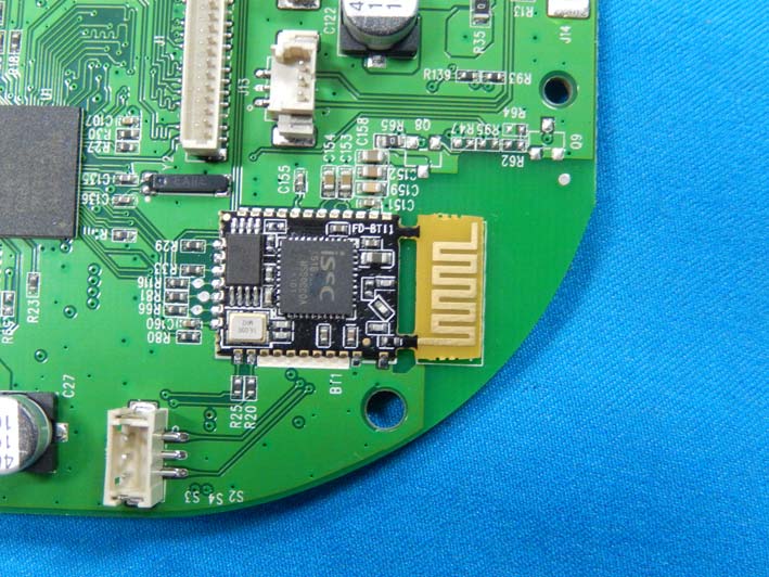
APPENDIX-PHOTOGRAPHS OF EUT CONSTRUCTIONAL DETAILS BT Antenna WIFI Antenna

RF Exposure Info

RF Exposure Compliance Requirement The product belongs to standalone portable device base the FCC rule part 2.1091&2.1093. The transmission frequencies of the device are between 100 MHz and 6 GHz. The worst case test separation distance is 5mm. The Max Conducted Output Power and SAR Test Exclusion Threshold (mW) are listed below: Transmit frequency (GHz) Max Conducted Output Power SAR Test Exclusion Threshold (mW) dBm mW 802.11b 2.412 9.40 8.71 10.0 2.437 9.65 9.23 10.0 2.462 9.27 8.45 10.0 802.11g 2.412 9.25 8.41 10.0 2.437 9.51 8.93 10.0 2.462 9.07 8.07 10.0 802.11n (HT20) 2.412 9.33 8.57 10.0 2.437 9.55 9.02 10.0 2.462 9.18 8.28 10.0 802.11n (HT40) 2.422 9.58 9.08 10.0 2.437 9.57 9.06 10.0 2.452 9.37 8.65 10.0 Remark: Level = Read Level + Cable Loss. The SAR Test Exclusion Threshold for 100 MHz to 6 GHz is calculated from: 1) The 1-g and 10-g SAR test exclusion thresholds for 100 MHz to 6 GHz at test separation distances ≤ 50 mm are determined by: [(max. power of channel, including tune-up tolerance, mW)/(min. test separation distance, mm)] · [√f(GHz)] ≤ 3.0 for 1-g SAR and ≤ 7.5 for 10-g extremity SAR, where f(GHz) is the RF channel transmit frequency in GHz Power and distance are rounded to the nearest mW and mm before calculation The result is rounded to one decimal place for comparison The test exclusions are applicable only when the minimum test separation distance is ≤ 50 mm and for transmission frequencies between 100 MHz and 6 GHz. When the minimum test separation distance is < 5 mm, a distance of 5 mm is applied to determine SAR test exclusion. Due to the Tune Up Power Specification is 9.8dBm only (9.55 mW) which is less than the SAR exemption threshold, either. According to SAR Exclusion Threshold in KDB 447498 (D01) General RF Exposure Guidance v05r02, the SAR report is not required.

Test Report

FCC RADIO TEST REPORT FCC ID: 2AC7RCAMIPPT08 Product: IP Pan and Tilt Wireless Camera Trade Name :Night Owl Model Name: CAM-IPPT-HDW Prepared for Henan Taide Electronic Technology CO., Ltd 16# Gong Ye San Road, Fengqiu Country, Xinxiang City, Henan Province Prepared by DongGuan Precise Testing Service Co.,Ltd. Room 203-204, 2F, Xinye Building, No.67 Shijing, Guanzhang Road, Dongguan, China Report No.: PT1410118012FB TEST RESULT CERTIFICATION Applicant’s name ........ Henan Taide Electronic Technology CO., Ltd Address ........................ 16# Gong Ye San Road, Fengqiu Country, Xinxiang City, Henan Province Manufacture's Name... Henan Taide Electronic Technology CO., Ltd Address ........................ 16# Gong Ye San Road, Fengqiu Country, Xinxiang City, Henan Province Product description Product name ................. IP Pan and Tilt Wireless Camera Model and/or type reference ..................... CAM-IPPT-HDW Serial Model .................... N/A In all, the original product and the alternative product are the same. Standards .................... FCC Part15.247 Test procedure ................ ANSI C63.10-2003 This device described above has been tested by PTS, and the test results show that the equipment under test (EUT) is in compliance with the FCC requirements. And it is applicable only to the tested sample identified in the report. This report shall not be reproduced except in full, without the written approval of PTS, this document may be altered or revised by PTS, personal only, and shall be noted in the revision of the document. Date of Test ...................................... Date (s) of performance of tests ....... 22 , Oct. 2014 ~ 27,Oct. 2014 Date of Issue ..................................... 27, Oct. 2014 Test Result......................................... Pass Testing Engineer : Technical Manager : Authorized Signatory : Assistant Supervisor Jacky Ou / Manager Report No.: PT1410118012FB DongGuan Precise Testing Service Co., Ltd Page 3 of 48 2 Test Summary Test Items Test Requirement Result Radiated Emissions 15.247 15.205(a) 15.209(a) PASS Conducted Emissions 15.207(a) PASS 6dB Bandwidth 15.247(a)(2) PASS Maximum Peak Output Power 15.247(b)(3),(4) PASS Power Spectral Density 15.247(e) PASS Band Edge 15.247(d) PASS Antenna Requirement 15.203 PASS Maximum Permissible Exposure (Exposure of Humans to RF Fields) 1.1307(b)(1) PASS Report No.: PT1410118012FB DongGuan Precise Testing Service Co., Ltd Page 4 of 48 TABLE OF CONTENTS 2 TEST SUMMARY 3 3 GENERAL INFORMATION 5 3.1 GENERAL DESCRIPTION OF E.U.T. 5 3.2 DETAILS OF E.U.T. 5 3.3 CHANNEL LIST 5 3.4 DESCRIPTION OF SUPPORT UNITS 5 3.5 TEST MODE 6 3.6 TEST FACILITY 7 3.7 TEST LOCATION 7 4 EQUIPMENT USED DURING TEST 8 4.1 EQUIPMENTS LIST 8 4.2 MEASUREMENT UNCERTAINTY 8 4.3 TEST EQUIPMENT CALIBRATION 8 5 CONDUCTED EMISSION 9 5.1 E.U.T. OPERATION 9 5.2 EUT SETUP 9 5.3 MEASUREMENT DESCRIPTION 10 5.4 CONDUCTED EMISSION TEST RESULT 10 6 SPURIOUS RADIATED EMISSIONS 11 6.1 EUT OPERATION : 11 6.2 TEST SETUP 12 6.3 SPECTRUM ANALYZER SETUP 13 6.4 TEST PROCEDURE 14 6.5 CORRECTED AMPLITUDE & MARGIN CALCULATION 14 6.6 SUMMARY OF TEST RESULTS 15 7 BAND EDGE MEASUREMENT 27 7.1 TEST PROCEDURE 27 7.2 TEST RESULT: 28 8 6 DB BANDWIDTH MEASUREMENT 32 8.1 TEST PROCEDURE: 32 8.2 TEST RESULT: 32 9 MAXIMUM PEAK OUTPUT POWER 39 9.1 TEST PROCEDURE: 39 9.2 BLOCK DIAGRAM OF TEST SETUP 39 9.3 3. KEEP THE EUT IN TRANSMITTING AT LOWEST, MEDIUM AND HIGHEST CHANNEL INDIVIDUALLY. RECORD THE MAX TEST RESULT: 39 10 POWER SPECTRAL DENSITY 41 10.1 TEST PROCEDURE: 41 10.2 TEST RESULT: 41 11 ANTENNA REQUIREMENT 48 Report No.: PT1410118012FB DongGuan Precise Testing Service Co., Ltd Page 5 of 48 3 General Information 3.1 General Description of E.U.T. Product Name : IP Pan and Tilt Wireless Camera Model No. : CAM-IPPT-HDW Brand Name : Night Owl Model Description : N/A Operation Frequency : 2412MHz ~ 2462MHz, 2422MHz~2452MHz Type of Modulation : IEEE 802.11b (CCK/QPSK/BPSK,11Mbps max.) IEEE 802.11g (BPSK/QPSK/16QAM/64QAM,54Mbps max.) IEEE 802.11n (BPSK/QPSK/16QAM/64QAM,HT20:72Mbps max., HT40:150Mbps max.) Oscillator : 40MHz for RF module Antenna Gain : 2dBi 3.2 Details of E.U.T. Technical Data : (1)DC 5V, 2000mA by adapter (2)AC 100-240V, 0.5A 3.3 Channel List Channel No. Frequency (MHz) Channel No. Frequency (MHz) Channel No. Frequency (MHz) Channel No. Frequency (MHz) 1 2412 2 2417 3 2422 4 2427 5 2432 6 2437 7 2442 8 2447 9 2452 10 2457 11 2462 12 - 3.4 Description of Support Units No. Equipment Manufacturer Model No. Serial No. 1. Notebook LENOVO X201i 75Y4408 Report No.: PT1410118012FB DongGuan Precise Testing Service Co., Ltd Page 6 of 48 3.5 Test Mode Table 1 Tests Carried Out Under FCC part 15.247 Test Items Mode Data Rate Channel TX/RX Maximum Peak Output Power 802.11b 11 Mbps 1/6/11 TX 802.11g 54 Mbps 1/6/11 TX 802.11n HT20 108 Mbps 1/6/11 TX 802.11n HT40 150 Mbps 3/6/9 TX Power Spectral Density 802.11b 11 Mbps 1/6/11 TX 802.11g 54 Mbps 1/6/11 TX 802.11n HT20 108 Mbps 1/6/11 TX 802.11n HT40 150 Mbps 3/6/9 TX Frequency Range 802.11b 11 Mbps 1/11 TX 802.11g 54 Mbps 1/11 TX 802.11n HT20 108 Mbps 1/11 TX 802.11n HT40 150 Mbps 3/9 TX Transmitter Spurious Emissions 802.11b 11 Mbps 1/6/11 TX 802.11g 54 Mbps 1/6/11 TX 802.11n HT20 108 Mbps 1/6/11 TX 802.11n HT40 150 Mbps 3/6/9 TX Note :Parameters set by test software during channel & power tests, the software provided by the customer was used to set the operating channels as well as the output power level. The RF output power set is the power expected by the manufacturer and is going to be fixed on the firmware of the final product . The EUT was programmed to be in continuously transmitting mode and the transmit duty cycle is not less than 98%. Table 2 Tests Carried Out Under FCC part 15.207 & FCC part 15.209 Test Item Test Mode Conduction Emission, 0.15MHz to 30MHz Communication Report No.: PT1410118012FB DongGuan Precise Testing Service Co., Ltd Page 7 of 48 3.6 Test Facility The test facility has a test site…

Text truncated - open the document above for the full version.

Test Setup Photos

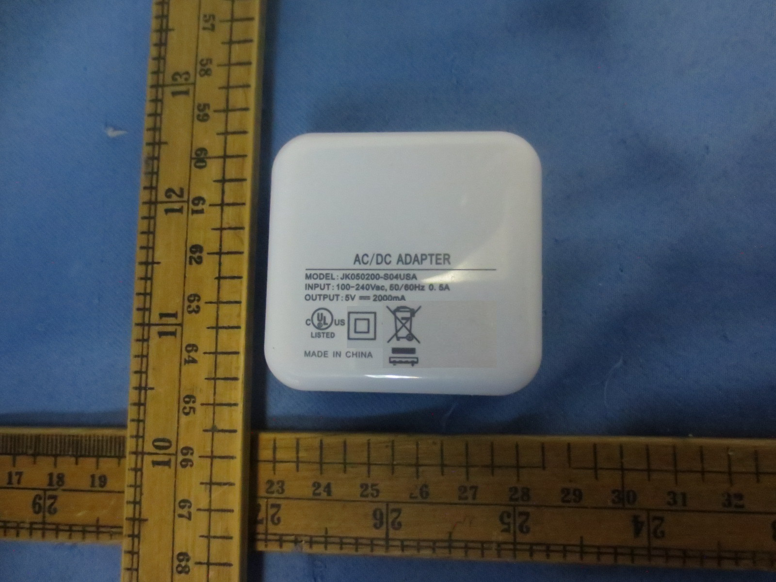
APPENDIX-PHOTOGRAPHS OF EUT CONSTRUCTIONAL DETAILS

Contact Information

Applicant

Anna Lee(Manager)
[email protected]0769-82691930Fax: 0769-82691920

Test Firm

Shenzhen NTEK Testing Technology Co., Ltd.Jason Chen
[email protected](86)-0755-61156588Fax: (86)-0755-61156599

Technical Specifications

#Rule PartsFrequency RangePower Output
215C2.42 GHz - 2.45 GHz9.10 mW
Confidentiality
Long Term
Grant Notes
Output Power listed is peak conducted. This device must not be co-located or operating in conjunction with any other antenna or transmitter.

Other Applications from Henan Taide Electronic Technology CO., LTD

IP CAMERA - FCC ID 2AC7RCAMIPC07 - Henan Taide Electronic Technology CO., LTD
2AC7RCAMIPC07

IP CAMERA

Nov 06, 2014

Equipment Class

DTS - Digital Transmission System