2ACAHAU5MRTRCHearing aid amplifier module
SBO Hearing A/S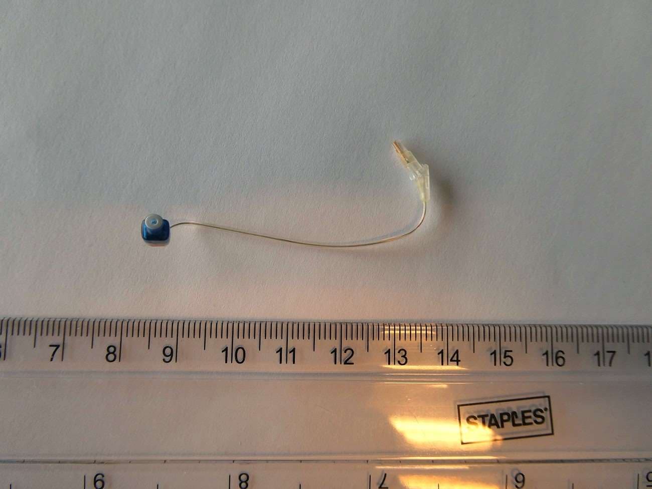
Click to zoom
Application Details
- Equipment Class
- DTS - Digital Transmission System
- Date of Grant
- Nov 05, 2020
- Application Purpose
- Original Equipment
- Date of Application
- Nov 05, 2020
- Equipment Note
- Hearing aid amplifier module
- Frequency Range
- 2402.00000000 - 2480.00000000
- Company
- SBO Hearing A/S
- Country
- Denmark
Documents & Files
Document Text
Text extracted from the exhibit documents filed with the FCC. Open a document above to read the original.
Users Manual
Radio Model - Quick Installation Guide Radio Model Name: DA_AU5_MNR_R SBO Hearing A/S, Kongebakken 9, 2765 Smorum - DK-Denmark, VAT-no.: DK39818558, www.sbohearing.com 1 The Aurora5 miniRITE T R radio model (DA_AU5_MNR_R) contains two radio transceivers running at 3.84 MHz and 2.4 GHz and both implemented on a single hardware platform. Additionally, a full featured RFID tag (IC5) operating at 865 MHz – 928 MHz with internal antenna has been glued onto the PCB. The RFID tag has no electrical connections related to the Aurora5 miniRITE T R radio module. The radio model is implemented in an engine module mounted on the main PCB with connection to the antennas, telecoil, the microphones, the speaker and the battery terminals. The radio model can be seen in 3D overview to the left. The 3.84 MHz radio is a low power, short range inductive radio transceiver (NFMI – Near Field magnetic Induction)working at a single channel at 3.84 MHz using MSK modulation with 320 kbit/s data rate and connected to a small coil antenna. The 2.4 GHz radio is a Bluetooth Low Energy (BLE core 5.0) transceiver using GFSK/2FSK modulation with 1 Mbit/s, 2 Mbit/s data rate also capable of proprietary reception modes (xBLE) with higher data rates (2 Mbit/s, 4 Mbit/s) using 2FSK/4FSK modulation. The 2.4 GHz radio is connected to a short wire antenna with a proprietary antenna connector. Below the main flex PCB of the Aurora5 miniRITE T R radio model with the most important electrical and electro-mechanical components can be seen: Aurora5 miniRITE T R Radio Model – 3D overview Radio Model - Quick Installation Guide Radio Model Name: DA_AU5_MNR_R SBO Hearing A/S, Kongebakken 9, 2765 Smorum - DK-Denmark, VAT-no.: DK39818558, www.sbohearing.com 2 The most important part of the radio model is the Engine Module (IC1) mounted on the main flex PCB, which connects it to both the EEPROM memory and all Aurora5 miniRITE T R Radio Model – Main PCB – Top side Radio Model - Quick Installation Guide Radio Model Name: DA_AU5_MNR_R SBO Hearing A/S, Kongebakken 9, 2765 Smorum - DK-Denmark, VAT-no.: DK39818558, www.sbohearing.com 3 external connections: On the top side these are the microphones, the battery terminals and the push button and coil antenna for the 3.84 MHz radio (L2). The telecoil (L1) is also used for wireless battery charging. The Aurora5 miniRITE T R radio model requires only a single cell battery and an external speaker (also incl. the wire antenna for the Bluetooth radio part) to be attached and plastic shells, defining the industrial design of a hearing aid end product and holding everything together, in order to be operational. Radio Model - Quick Installation Guide Radio Model Name: DA_AU5_MNR_R SBO Hearing A/S, Kongebakken 9, 2765 Smorum - DK-Denmark, VAT-no.: DK39818558, www.sbohearing.com 4 On the bottom side of the main PCB of the Aurora5 miniRITE T R radio model the connector for the speaker unit assembly (where the wire antenna for the Bluetooth radio is an integrated part), the programming connector, EEPROM memory can be seen: The most important parts inside the Engine module are a Digital-Signal-Processor (DSP), a radio Front-End (FE) chip for the 3.84 MHz radio part and an RF chip for the Bluetooth radio part – all mounted on a small rigid PCB again mounted on the main flex PCB. The Aurora5 miniRITE T R radio model also includes all voltage regulators and buffered data programming inputs on board. The DSP is the main processor controlling the functionality of both radios in the Aurora5 miniRITE T R radio model. The Aurora5 miniRITE T R radio model is intended to be installed in Oticon, Bernafon, Sonic, Philips and affiliated private labels wireless hearing aid devices of the miniRITE T R (Receiver-In-The-Ear) wearing style. Aurora5 miniRITE T R Radio Model – Main PCB – Top/Bottom side SBO Hearing A/S, Kongebakken 9, 2765 Smorum - DK-Denmark, VAT-no.: DK39818558, www.sbohearing.com 5 Radio Model - Regulatory Label Information for USA & Canada Radio Model Name: DA_AU5_MNR_R Contains: FCC ID: 2ACAHAU5MRTRC IC: 11936A-AU5MRTRC NOTICE: This device complies with Part 15, Part 15.223, Part 15.247 of the FCC Rules and with RSS-210 and RSS-247 of Industry Canada. Operation is subject to the following two conditions: (1) This device may not cause harmful interference, and (2) This device must accept any interference received, including interference that may cause undesired operation. Changes or modifications made to this equipment not expressly approved by SBO Hearing A/S may void the FCC authorization to operate this equipment. Le présent appareil est conforme aux CNR d'Industrie Canada applicables aux appareils radio exempts de licence. L'exploitation est autorisée aux deux conditions suivantes: (1) l'appareil ne doit pas produire de brouillage, et (2) l'utilisateur de l'appareil doit accepter tout brouillage radioélectrique subi, même si le brouillage est susceptible d'en compromettre le fonctionnement. SBO Hearing A/S, Kongebakken 9, 2765 Smorum - DK-Denmark, VAT-no.: DK39818558, www.sbohearing.com 6 Radio Model - Regulatory Label Information for Japan Radio Model Name: DA_AU5_MNR_R Description: Radio module with 2.4 GHz low power transceiver to be integrated into various hearing instruments and associated devices. Regulatory label: This device is granted pursuant to the Japanese Radio Law (電波法) and the Japanese Telecommunications Business Law ( 電気通信事業法) under the grant ID n° 認証番号: 202- SMI046 This device should not be modified (otherwise the granted designation number will become invalid) 本製品の改造は禁止されています。(適合証明番号などが無効となります。) NB: The regulatory label is not shown on the radio module itself or any end products with it, since they are too small for the label to be readable without any optical aids or magnification. Below the radio module is shown, indicating a size of about 6.5x11x28 mm. Radio module from the side Radio module from the top side (button side) Radio module from bottom side NB: The regulatory label for Jap…
Text truncated - open the document above for the full version.
Cover Letter(s)
SBO Hearing A/S, Kongebakken 9, 2765 Smorum - DK-Denmark, CVR-no.: 39818558, www.sbohearing.com CONFIDENTIALITY REQUEST for Certification Service in USA Federal Communication Commission Equipment Authorization Division, Application Processing Branch 7435 Oakland Mills Road Columbia, MD 21048 2020-09-29 TO WHOM IT MAY CONCERN Pursuant to Paragraphs §0.457 and 0.459 of the Commission’s Rules (47 C.F.R.) and Section §552(b)(4) of the Freedom of Information Act, we requests confidentiality for the following products: FCC ID Model name 2ACAHAU5MRTRC DA_AU5_MNR_R For the product stated above, we request permanent confidentiality for exhibits which contain Operational Description, Block Diagram, Schematics, Parts Lists and Tune Up Information. The above exhibits contain our trade secrets and proprietary information that could be of benefit to our competitors. If you have any questions, please feel free to contact me at the address shown below. Signed for SBO Hearing A/S Per Klaus Nielsen Certification Manager, Regulatory Affairs Email: [email protected]
Cover Letter(s)
SBO Hearing A/S, Kongebakken 9, 2765 Smorum - DK-Denmark, CVR-no.: 39818558, www.sbohearing.com Receiver Federal Communication Commission Equipment Authorization Devision, Application Processing Branch 7435 Oakland Mills Road Columbia, MD 21048 Certification and Engineering Bureau Industry Canada Spectrum Engineering Branch 3701 Carling Avenue, Building 94 Ottawa, Ontario K2H 8S2 Subject: Limited Modular Approval Statement Date: 2020-09-22 FCC Certification Number: 2ACAHAU5MRTRC Only applicable for IC certification: ISED Company Number: 11936A UPN: (Unique Product No) AU5MRTRC HVIN (Hardware Ver. ID): DA_AU5_MNR_R PMN: (Product Marketing Name) DA_AU5_MNR_R HMN: (Host Marketing Name) N/A FVIN: (Firmware Version Identification Number) N/A TO WHOM IT MAY CONCERN Pursuant to Paragraphs RSP-100 Issue 12 August 2019 Annex D and CFR § 15.212, we herewith declare for our module. Modular approval requirement Yes No * (a) The radio elements must have the radio frequency circuitry shielded. Physical/discrete and tuning capacitors may be located external to the shield but must be on the module assembly. X *Please provide a detailed explanation if the answer is “No.”: There is no complete RF shield attached to the radio module, only the ground layer in its PCB. Therefore, we are only requesting a limited modular approval for the module. There is no tuning or adjustment after installation of the module. (b) The module shall have buffered modulation/data input(s) (if such inputs are provided) to ensure that the module will comply with the requirements set out in the applicable RSS standard / FCC part 15 under conditions of excessive data rates or over- modulation. X *Please provide a detailed explanation if the answer is “No.”: SBO Hearing A/S, Kongebakken 9, 2765 Smorum - DK-Denmark, CVR-no.: 39818558, www.sbohearing.com (c) The module shall have its own power supply regulation on the module. This is to ensure that the module will comply with the requirements set out in the applicable standard regardless of the design of the power supplying circuitry in the host device which houses the module. X *Please provide a detailed explanation if the answer is “No.”: (d) The module shall comply with the provisions for external power amplifiers and antennas detailed in this standard. The equipment certification submission shall contain a detailed description of the configuration of highest antenna gain for each type of antenna. X *Please provide a detailed explanation if the answer is “No.”: (e) The module shall be tested for compliance with the applicable standard in a stand-alone configuration, i.e. the module must not be inside another device during testing. X *Please provide a detailed explanation if the answer is “No.”: (f) The module shall comply with applicable RSS-102 exposure requirements and any applicable FCC RF exposure requirement which are based on the intended configuration/integration in a host. X *Please provide a detailed explanation if the answer is “No.”: Only applicable for FCC certification: (g) The module must be equipped with either a permanently affixed label or must be capable of electronically displaying its FCC identification number. (X) *Please provide a detailed explanation if the answer is “No.”: The module is intended to be used inside SBO Hearing and affiliated OEM branded hearing instruments only (Oticon, Bernafon, Sonic, Philips etc.), which are too small to carry the IC label legible without magnification. Therefore, the label is put in the installation guide and/or user manual, but not on the products carrying the module inside. Only applicable for FCC certification: (i) The modular transmitter complies with all applicable FCC rules. Instructions for maintaining compliance are given in the user instructions. X If you have any questions, please feel free to contact us at the address shown below SBO Hearing A/S, Kongebakken 9, 2765 Smorum - DK-Denmark, CVR-no.: 39818558, www.sbohearing.com Signed on behalf of SBO Hearing A/S, Per Klaus Nielsen Certification Manager, Regulatory Affairs SBO Hearing A/S, Kongebakken 9 2765 Smorum - DK-Denmark Phone: +45 3913 7100 INFO for applicant: LMA may be granted when one or more of the requirements in the table above cannot be demonstrated. LMA will also be issued in those instances where applicants can demonstrate that they will retain control over the final installation of the device, such that compliance of the end product is assured. In such cases, an operating condition on the LMA for the module must state that the module is only approved for use when installed in devices produced by a specific manufacturer. When LMA is sought, the application for equipment certification must specifically state how control of the end product, into which the module will be installed, will be maintained, such that full compliance of the end product is always ensured.
Cover Letter(s)
SHORT-TERM CONFIDENTIALITY REQUEST Federal Communication Commission Equipment Authorization Division, Application Processing Branch 7435 Oakland Mills Road Columbia, MD 21048 2020-09-29 TO WHOM IT MAY CONCERN Pursuant to Paragraphs §0.457 and 0.459 of the Commission’s Rules (47 C.F.R.) and Section §552(b)(4) of the Freedom of Information Act, we requests short term confidentiality for the following product: FCC ID Number Product Title/Model 2ACAHAU5MRTRC DA_AU5_MNR_R For the product stated above, we request that the following information be held confidential: 1. External and Internal Photographs 2. Test Setup Photos 3. User Manual We request this confidentiality on the basis of ensuring that business sensitive information remains confidential until the actual marketing of our new device, which is planned for 2020-12-16 If you have any questions, please feel free to contact me at the address shown below. Sincerely, Name: Per Klaus Nielsen Certification Manager Company: SBO Hearing A/S Address: Kongebakken 9, DK-2765 Smoerum, Denmark Phone: +45 3917 7100 Email: [email protected]
External Photos
SBO Hearing A/S, Kongebakken 9, 2765 Smorum - DK-Denmark, CVR-no.: 39818558, www.sbohearing.com DA_AU5_MNR_R external pictures The DA_AU5_MNR_R hearing aid module stack up Left side SBO Hearing A/S, Kongebakken 9, 2765 Smorum - DK-Denmark, CVR-no.: 39818558, www.sbohearing.com Right side with battery interface clip Bottom side with interface connector for speakers/ Bluetooth antenna (left). Telecoil at right. SBO Hearing A/S, Kongebakken 9, 2765 Smorum - DK-Denmark, CVR-no.: 39818558, www.sbohearing.com Speaker wire and Bluetooth antenna with proprietary connector
ID Label/Location Info
SBO Hearing A/S, Kongebakken 9, 2765 Smorum - DK-Denmark, CVR-no.: 39818558, www.sbohearing.com Smørum, 2020-09-29 Manufacturer’s Statement FCC ID location justification FCC ID: 2ACAHAU5MRTRC TO WHOM IT MAY CONCERN We, the undersigned, hereby submit the justification for placing the FCC ID in the Associated User Manual for the Hearing Aids having the above-mentioned FCC IDs. According to KDB Publication 784748 D01, when the device is so small, or for such use that it is impracticable to label with a font size that is four points or larger (and the device does not utilize electronic labelling), then the FCC ID shall be placed in the user manual. Hearing Aids having the above-mentioned FCC IDs are so small and considering the dimensions of the equipment and the label area, it is impracticable to label FCC ID with a font size required on the devices. Therefore, the FCC ID label is placed in the User Manual. Yours sincerely, Per Klaus Nielsen Certification Manager, Regulatory Affairs
Internal Photos
SBO Hearing A/S, Kongebakken 9, 2765 Smorum - DK-Denmark, CVR-no.: 39818558, www.sbohearing.com DA_AU5_MNR_R Internal pictures The DA_AU5_MNR_R module parts PCB showing button and microphone side SBO Hearing A/S, Kongebakken 9, 2765 Smorum - DK-Denmark, CVR-no.: 39818558, www.sbohearing.com PCB showing the connector side
RF Exposure Info
BNetzA - CAB - 02/21 - 102 D - P L - 1 2 0 7 6 - 0 1 - 0 3 SAR Test exclusion documentation according to FCC KDB 447498, RSS-102 Report identification number: 1-0213/20-02-18 Exclusion (FCC_ISED) contains the module with the following certification numbers FCC ID 2ACAHAU5MRTRC ISED number 11936A-AU5MRTRC HVIN (Hardware Version Identification Number) DA_AU5_MNR_R PMN (Product Marketing Name) DA_AU5_MNR_R FVIN (Firmware Version Identification Number) -/- HMN (Host Marketing Name) -/- This report is electronically signed and valid without handwriting signature. For verification of the electronic signatures, the public keys can be requested at the testing laboratory. Document authorised: Alexander Hnatovskiy Marco Scigliano Lab Manager Testing Manager Radio Communications & EMC Radio Communications & EMC Test report no.: 1-0213/20-02-18 © CTC advanced GmbH Page 2 of 3 Technologies: Max. rated power: (AVG) Max. gain: Max. EIRP: BT LE 2450 MHz 2.6 dBm / 1.82 mW <1.7 dBi < 4.5 dBm / 2.82 mW Note: See results in the following Annex A for details on the AVG output power and its derivation from the measurements. SAR test exclusion according to KDB447498 (General RF Exposure Guidance v06) Equation from Chapter 4.3.1: Standalone SAR test exclusion considerations page 11 and ff. (1) Standalone SAR test exclusion for 100 MHz to 6 GHz at test separation distances ≤ 50mm ( Threshold 1-g;10-g ) × d seperation / f 0.5 where Threshold 1-g;10-g is 3 for 1-g; 7.5 for 10-g d seperation is the min. test separation distance; 5mm is used if the distance is less f is the RF channel transmit frequency The table below gives the calculated maximal power that could be used for source based time averaged conducted or radiated power, adjusted for tune up tolerance. If this is at or below the calculated value the DUT is exempted from SAR evaluation. frequencyd separation Powerlimit [MHz][mm][mW][dBm][mW] 2450.00539.584.502.82yes Threshold 1-g Exclusion P max-declared SAR test exclusion according to RSS-102 Issue 5 Section 2.5.1/Table 1 The table below gives the calculated maximal power that could be used for source based time averaged conducted or radiated power, adjusted for tune up tolerance. If this is at or below the calculated value the DUT is exempted from SAR evaluation. frequency d separation Powerlimit [MHz] [mm] [mW] [dBm] [mW] 2450.00 5 1 g 4.00 4.50 2.82 yes tissue volume P max-declared Exclusion The limits above are defined for body worn application and therefore cover all use cases. Test report no.: 1-0213/20-02-18 © CTC advanced GmbH Page 3 of 3 An nex A: Deri vat ion o f t he max. AVG ou tp ut pow er Outputpower: Max AVG Outputpower = Peak max - Duty cycle correction = 7.4 dBm – 4.8dB = 2.6dBm Peak output power Frequency 2404 MHz 2440 MHz 2478 MHz Maximum output power conducted [dBm] 1 Msps -1.3 0.8 -0.4 Maximum output power conducted [dBm] 2 Msps High power 6.3 7.4 6.8 Antenna gain: Note: Details for Output power and Antenna gain can be seen in CTC advanced GmbH report 1-0213/20-02-03 Duty Cycle correction: 0.328 TX on one channel TX on two channel Duty cycle: 0.328 (=4.8dB) Duty cycle: 0.328 (=4.8dB) Antenna Gain Low channel (2402 MHz) Mid channel (2440 MHz) High channel (2480 MHz) Gain [dBi] Declared 1.7 1.3 1.4
Test Report
BNetzA - CAB - 02/21 - 102 TEST REPORT Test report no.: 1-0213/20-02-03 Testing laboratory Applicant CTC advanced GmbH Untertuerkheimer Strasse 6 – 10 66117 Saarbruecken / Germany Phone: + 49 681 5 98 - 0 Fax: + 49 681 5 98 - 9075 Internet: https://www.ctcadvanced.com e-mail: [email protected] Accredited Testing Laboratory: The testing laboratory (area of testing) is accredited according to DIN EN ISO/IEC 17025 (2018-03) by the Deutsche Akkreditierungsstelle GmbH (DAkkS) The accreditation is valid for the scope of testing procedures as stated in the accreditation certificate starting with the registration number: D-PL-12076-01. SBO Hearing A/S Kongebakken 9 2765 Smørum / DENMARK Phone: +45 39 17 71 00 Contact: Per Klaus Nielsen e-mail: [email protected] Phone: +4541499503 Manufacturer SBO Hearing A/S Kongebakken 9 2765 Smørum / DENMARK Test standard/s FCC - Title 47 CFR Part 15 FCC - Title 47 of the Code of Federal Regulations; Chapter I; Part 15 - Radio frequency devices RSS - 247 Issue 2 Digital Transmission Systems (DTSs), Frequency Hopping Systems (FHSs) and Licence - Exempt Local Area Network (LE-LAN) Devices For further applied test standards please refer to section 3 of this test report. Test Item Kind of test item: Hearing aid amplifier module Model name: DA_AU5_MNR_R FCC ID: 2ACAHAU5MRTRC IC: 11936A-AU5MRTRC Frequency: DTS band 2400 MHz to 2483.5 MHz Technology tested: Bluetooth® LE + 2 Mbit/s RX proprietary + 4 Mbit/s RX proprietary Antenna: Wire antenna, length 5 Power supply: 4.2 V DC by Li-Ion rechargeable battery Temperature range: 0°C to +40°C This test report is electronically signed and valid without handwritten signature. For verification of the electronic signatures, the public keys can be requested at the testing laboratory. Test report authorized: Test performed: Marco Bertolino Mihail Dorongovskij Lab Manager Lab Manager Radio Communications Radio Communications Test report no.: 1-0213/20-02-03 © CTC advanced GmbH Page 2 of 59 1 Table of contents 1 Table of contents ............................................................................................................................................. 2 2 General information ......................................................................................................................................... 3 2.1 Notes and disclaimer ............................................................................................................................ 3 2.2 Application details ................................................................................................................................ 3 2.3 Test laboratories sub-contracted ......................................................................................................... 3 3 Test standard/s, references and accreditations .............................................................................................. 4 4 Reporting statements of conformity – decision rule ...................................................................................... 5 5 Test environment ............................................................................................................................................. 6 6 Test item .......................................................................................................................................................... 6 6.1 General description ............................................................................................................................... 6 6.2 Additional information .......................................................................................................................... 7 7 Sequence of testing ......................................................................................................................................... 8 7.1 Sequence of testing radiated spurious 9 kHz to 30 MHz ..................................................................... 8 7.2 Sequence of testing radiated spurious 30 MHz to 1 GHz .................................................................... 9 7.3 Sequence of testing radiated spurious 1 GHz to 18 GHz ................................................................... 10 7.4 Sequence of testing radiated spurious above 18 GHz ....................................................................... 11 8 Description of the test setup.......................................................................................................................... 12 8.1 Shielded semi anechoic chamber ....................................................................................................... 13 8.2 Shielded fully anechoic chamber ........................................................................................................ 14 8.3 Radiated measurements > 18 GHz ...................................................................................................... 15 8.4 Conducted measurements Bluetooth system .................................................................................... 16 8.5 AC conducted ...................................................................................................................................... 17 9 Measurement uncertainty .............................................................................................................................. 18 10 Summary of measurement results ......................................................................................................... 19 11 Additional comments .............................................................................................................................. 20 12 Measurement results .............................................................................................................................. 21 12.1 System gain ...................................................................................................................…
Text truncated - open the document above for the full version.
Test Report
Measurement Results 1-0213/20-02-03_log1_conducted Test logging This addendum is electronically signed and valid without handwritten signature. For verification of the electronic signatures, the public keys can be requested at the testing laboratory. Document authorized: Mihail Dorongovskij Lab Manager Radio Communications CTC advanced GmbHUntertuerkheimer Strasse 6-10 66117 Saarbruecken / Germany Phone: +49 681 5 98 - 0 Fax: +49 681 5 98 - 9075 web: ctcadvanced.com e-mail: [email protected] Table of Content IUT Summary3 1. FCC Part 15.247 Maximum Peak Conducted Output Power DTS ~ BT LE 1 Msps4 2. FCC Part 15.247 Bandwidth 6dB DTS ~ BT LE 1 Msps11 3. FCC Part 15.247 Peak Power Spectral Density DTS ~ BT LE 1 Msps15 4. FCC Part 15.247 Bandwidth 99PCT-20dB ~ BT LE 1 Msps19 5. FCC Part 15.247 TX Spurious Conduced ~ BT LE 1 Msps26 6. FCC Part 15.247 Maximum Peak Conducted Output Power DTS ~ BT LE 2 Msps30 7. FCC Part 15.247 TX Spurious Conduced ~ BT LE 2 Msps37 8. FCC Part 15.247 Bandwidth 6dB DTS ~ BT LE 2 Msps41 9. FCC Part 15.247 Peak Power Spectral Density DTS ~ BT LE 2 Msps45 10. FCC Part 15.247 Bandwidth 99PCT-20dB ~ BT LE 2 Msps49 11. FCC Part 15.247 Maximum Peak Conducted Output Power DTS ~ BT LE 2 Msps56 12. FCC Part 15.247 Bandwidth 6dB DTS ~ BT LE 2 Msps63 13. FCC Part 15.247 Peak Power Spectral Density DTS ~ BT LE 2 Msps67 14. FCC Part 15.247 TX Spurious Conduced ~ BT LE 2 Msps71 15. FCC Part 15.247 Bandwidth 99PCT-20dB ~ BT LE 2 Msps75 Document No. 1-0213/20-02-03_log1_conducted2/81 IUT Summary IUT DEFINITION & Common settings ManufacturerSBO Hearing A/S Type DA_AU5_MNR_R Serial No. | Setup No.64155776 / 64155751 | 1.0 SW Version | HW Versionxble_qual_app 54.4 | FL/rev05 Comment 1 | 2 | Tlow | Tmid | Thigh [°C] 0 | 20 | 40 Vlow | Vmid | Vhigh [V] @Imax [A] 3.4 | 4.2 | 4.2 @1 Auto Control enabled Power Supply | Climatic BoxNo | No Antenna Gain [dBi] (only considered if explicitly mentioned in testresult)0 Additional Path Loss [dB]0.8 IUT Common Settings BT Low Energy Intermodulation Value N3 Image Freq. Low | Mid | High [MHz]-2 | -2 | -2 for 1 Mbps / -4 | -4 | -4 for 2 Mbps Power Class2 1 Mbps supportedTrue | TXpayload 255 | RXpayload 255 2 Mbps supportedTrue | TXpayload 255 | RXpayload 255 Longrange S8 supportedFalse | TXpayload 255 | RXpayload 255 Longrange S2 supportedFalse | TXpayload 255 | RXpayload 255 Signaling Settings USB_RS232 | HCI | 9 | 9600 | None | S1 | None | On Signaling RF Settings RF1com | 0 | 0 | On | User InteractionNo Switch Matrix & Pathcompensation enabledYes Document No. 1-0213/20-02-03_log1_conducted3/81 1. FCC Part 15.247 Maximum Peak Conducted Output Power DTS ~ BT LE 1 Msps Test References TC Start28.09.2020 09:37:52 Ambit Temp [°C] | Humidity [rel%] 22.0 | 42 System Version1.0.0.51 Test SpecificationFCC Part 15.247 Test MethodDTS: KDB 558074 D01 V05 - Chapter 8.3.1.1 RBW ≥ DTS Bandwidth Class / TC VersionTC_VM_FCC15247_Maximum_Peak_Conducted_Output_Power_DTS_V01 Version: 0.0.1 My DescriptionFCC 15.247 Maximum Peak Output Power Conducted DTS - BT LE 1 Msps Add. Information Test Parameter Technology to testBT LE 1 Msps Antenna Port used1 Temperaturemid Voltagemid Frequency low to testTrue | Freq [MHz] 2402 Frequency mid to testTrue | Freq [MHz] 2440 Frequency high to testTrue | Freq [MHz] 2480 Switched PathIUT - SignalingUnit - SpectrumAnalyzer Devices in useSigBT: Rohde&Schwarz,CMW,1201.0002k75/100683,3.7.170 | SA: Rohde&Schwarz,FSV-30,1321.3008K30/103809,3.60 Document No. 1-0213/20-02-03_log1_conducted4/81 Test at TX 2402 MHz DTM Connection check Test DescriptionLower LimitUpper LimitMeasuredUnitVerdict Connection result------------PASS READ SA SETTINGS: RefLevel [dBm] | RefLevelOffset [dB] | InpAtt [dB]3.67 | 10.89 | 10 Start [MHz] | Stop [MHz]2401.000 | 2403.000 RBW [MHz] | VBW [MHz]0.100000 | 0.300000 Detector | TraceModePOS | MAXH Sweep: Time [ms] | Count | Points per Section | Type50 | 200 | 10001 | SWE DTS Bandwidth Test DescriptionLower LimitUpper LimitMeasuredUnitVerdict DTS Bandwidth (6dB)------652kHzINFO Plot_FCC Part 15.247 Maximum Peak Conducted Output Power DTS ~ BT LE 1 Msps DTS BW_28092020_093820.png READ SA SETTINGS: RefLevel [dBm] | RefLevelOffset [dB] | InpAtt [dB]8.67 | 10.89 | 15 Start [MHz] | Stop [MHz]2401.000 | 2403.000 RBW [MHz] | VBW [MHz]1.000000 | 3.000000 Detector | TraceModePOS | MAXH Sweep: Time [ms] | Count | Points per Section | Type50 | 200 | 1001 | SWE RESULT Test DescriptionLower LimitUpper LimitMeasuredUnitVerdict Peak Power---30.00-1.25dBmPASS Peak Power---10000.749894mWPASS Frequency at Peak------2402.272MHzINFO Document No. 1-0213/20-02-03_log1_conducted5/81 Plot_FCC Part 15.247 Maximum Peak Conducted Output Power DTS ~ BT LE 1 Msps_28092020_093835.png Document No. 1-0213/20-02-03_log1_conducted6/81 Test at TX 2440 MHz DTM Connection check Test DescriptionLower LimitUpper LimitMeasuredUnitVerdict Connection result------------PASS READ SA SETTINGS: RefLevel [dBm] | RefLevelOffset [dB] | InpAtt [dB]5.73 | 10.9 | 10 Start [MHz] | Stop [MHz]2439.000 | 2441.000 RBW [MHz] | VBW [MHz]0.100000 | 0.300000 Detector | TraceModePOS | MAXH Sweep: Time [ms] | Count | Points per Section | Type50 | 200 | 10001 | SWE DTS Bandwidth Test DescriptionLower LimitUpper LimitMeasuredUnitVerdict DTS Bandwidth (6dB)------653kHzINFO Plot_FCC Part 15.247 Maximum Peak Conducted Output Power DTS ~ BT LE 1 Msps DTS BW_28092020_093902.png READ SA SETTINGS: RefLevel [dBm] | RefLevelOffset [dB] | InpAtt [dB]10.73 | 10.9 | 15 Start [MHz] | Stop [MHz]2439.000 | 2441.000 RBW [MHz] | VBW [MHz]1.000000 | 3.000000 Detector | TraceModePOS | MAXH Sweep: Time [ms] | Count | Points per Section | Type50 | 200 | 1001 | SWE RESULT Test DescriptionLower LimitUpper LimitMeasuredUnitVerdict Peak Power---30.000.75dBmPASS Peak Power---10001.188502mWPASS Frequency at Peak---…
Text truncated - open the document above for the full version.
Contact Information
Applicant
Per Klaus Nielsen(Certification Manager)
Test Firm
cetecom advanced GmbHGerald Schmidt
Technical Specifications
| # | Rule Parts | Frequency Range | Power Output |
|---|---|---|---|
| 1 | 15C | 2.40 GHz - 2.48 GHz | 7.40 mW |
Other Applications from SBO Hearing A/S
2ACAH-SBO002
May 22, 2026Hearing aid
Equipment Class
DTS - Digital Transmission System2ACAHAU5MNRR
Jan 18, 2024Hearing instrument amplifier module
Equipment Class
DTS - Digital Transmission System
2ACAHWLP020
Aug 28, 2014Programming device for hearing aids
Equipment Class
DXX - Part 15 Low Power Communication Device Transmitter