Text extracted from the exhibit documents filed with the FCC. Open a document above to read the original.
Changes or modifications to this unit not expressly approved IMPORTANT Safety Important Safety Instructions Heed all warnings. Do not use this apparatus near water. Do not block any ventilation openings. Install in accordance with the manufacturer’s instructions. Do not install near any heat sources such as radiators, heat registers, stoves, or other devices (including amplifiers) that produce heat. Only use attachments/ accessories specified by the manufacturer. Refer all servicing to qualified service personnel. Servicing is required when the device has been damaged in any way, such as power-supply cord or plug is damaged, liquid has been spilled or objects have fallen into the device, the device has been exposed to rain or moisture, does not operate normally, or has been dropped. Devices shall not be exposed to dripping or splashing. Do not place any sources of danger on the device (e.g. liquid filled objects, lighted candles). Warning Never remove the casing of this apparatus. Never place this apparatus on other electrical equipment. Your Bluetooth Speaker Power supply 1.The speaker can operate on built-in rechargeable battery. 2.To recharge the built-in battery 3.Connect micro USB socket with PC through supplied USB cable. 4.The power indicator (red) turns on. 5.The power indicator (red) tures off when it’s fully charged. Play Play from a Bluetooth device Note: The effective operation range between the speaker and your Bluetooth device is approximately 10 meters (30 feet) Bluetooth Mode: 1.Turn on speaker, the indicator light is flashing (when power on, the blue light is on, when waiting pairing, the blue light is flashing fast, after paired, the blue light is flashing slowly. 2.Turn on bluetooth function of device (i.e. Phone, Computer or Tablet PC...) 3.Search and select bluetooth speaker , i.e. “99E-XXXX” to pair. You will hear “paired” from bluetooth speaker. For some devices, you need to input password “0000” to pair. 4.Playing music and it is outputted from bluetooth speaker 5.Turn off the speaker if you don't use it. FM radio mode 1.press" "(if no this key)long press" "and into the radio mode. 2.press" "enter the automatic search,the bluetooth loudspeaker will be automatically stored the FM radio which had already searched,after searching the radio,it Will play the first TV show which had already stored. 3.press" / ",you can choose up and down of the storage station. 4.press" "(if no this key)long press" "return to the bluetooth mode. (before searching and receiving,must insert the line of LINE IN to the AUX interface for antenna,if no the AUX connector,do the antenna with USB cable) Tip You can speak to the MIC to get the best speakerphone performance. TF CARD: 1.Insert TF card, bluetooth speaker will switch to TF card mode by default. 2.Bluetooth speaker will play the musics of TF card automatically. Support formats include: WMA/MP3/WAV. 3.Push “ / “ button to control the sound volume. 4.Push “ / “ button to choose song to play. Q&A: Please don't try to repair the product by yourself. No Power: Please recharge the bluetooth speaker. No Sound: Please adjust the sound volume of your bluetooth device. Please make sure you bluetooth device is in the effective range. Please check the selected audio source is correct. Speaker No sound: Please reboot the bluetooth speaker. Specification: Note: product specification can be changed without notify. Rated Output Power DC power input Built-in Li-ion battery Battery working time Bluetooth specification Advanced features Range Bluetooth Speaker 3W RMS USB 5V 500MAH 3.7V 600MAH >4 Hours V2.1+EDR Echo and noise elimination 10 meters (No obstacle) DC 5V TF ()BL145/BL155/RE195 AUX User Manual Brand name:goldhorse Model name:BL145 FCC ID:2ACATBL145 This device complies with part 15 of the FCC rules. Operation is subject to the following two conditions: (1) this device may not cause harmful interference, and (2) this device must accept any interference received, including interference that may cause undesired operation by the party responsible for compliance could void the user’s authority to operate the equipment.?
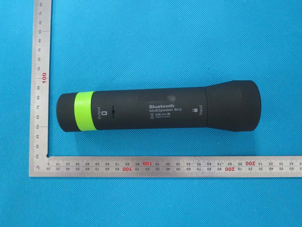
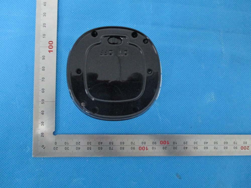
External Photos Model: BL145 TOP VIEW OF EUT BOTTOM VIEW OF EUT FRONT VIEW OF EUT BACK VIEW OF EUT LEFT VIEW OF EUT RIGHT VIEW OF EUT Model: BL155 FRONT VIEW OF EUT BACK VIEW OF EUT
FCC ID/IC Label Location Bluetooth Speaker Model name:BL145 Brand name:goldhorse FCC ID: 2ACATBL145 BL155,RE195
Internal Photos OPEN VIEW OF EUT INTERNAL VIEW OF EUT-1 BT Antenna INTERNAL VIEW OF EUT-2 INTERNAL VIEW OF EUT-3 INTERNAL VIEW OF EUT-4
Report No.: AGC01565140401FE03 Page 1 of 60 FCC Test Report Report No.: AGC01565140401FE03 FCC ID : 2ACATBL145 APPLICATION PURPOSE : Original Equipment PRODUCT DESIGNATION : Bluetooth Speaker BRAND NAME : goldhorse MODEL NAME : BL145, BL155, RE195 CLIENT : Shenzhen Goldhorse Electronics Co., Ltd. DATE OF ISSUE : Apr.24, 2014 STANDARD(S) : FCC Part 15 Rules REPORT VERSION : V1.0 Attestation of Global Compliance (Shenzhen) Co., Ltd CAUTION: This report shall not be reproduced except in full without the written permission of the test laboratory and shall not be quoted out of context. Report No.: AGC01565140401FE03 Page 2 of 60 Report Revise Record Report Version Revise Time Issued Date Valid VersionNotes V1.0 / Apr.24, 2014 Valid Original Report Report No.: AGC01565140401FE03 Page 3 of 60 TABLE OF CONTENTS 1. VERIFICATION OF CONFORMITY ...................................................................................... 5 2. GENERAL INFORMATION .................................................................................................. 6 2.1. PRODUCT DESCRIPTION ........................................................................................................... 6 2.2. TABLE OF CARRIER FREQUENCYS .......................................................................................... 6 2.3. RECEIVER INPUT BANDWIDTH ................................................................................................. 7 2.4. EXAMPLE OF A HOPPING SEQUENCY IN DATA MODE ........................................................... 7 2.5. EQUALLY AVERAGE USE OF FREQUENCIES AND BEHAVIOUR ............................................ 7 2.6. RELATED SUBMITTAL(S) / GRANT (S) ....................................................................................... 8 2.7. TEST METHODOLOGY................................................................................................................ 8 2.8. SPECIAL ACCESSORIES ............................................................................................................ 8 2.9. EQUIPMENT MODIFICATIONS ................................................................................................... 8 3. MEASUREMENT UNCERTAINTY........................................................................................ 9 4. DESCRIPTION OF TEST MODES ........................................................................................ 9 5. SYSTEM TEST CONFIGURATION .................................................................................... 10 5.1. CONFIGURATION OF EUT SYSTEM ........................................................................................ 10 5.2. EQUIPMENT USED IN EUT SYSTEM ....................................................................................... 10 5.3. SUMMARY OF TEST RESULTS ................................................................................................ 10 6. TEST FACILITY .................................................................................................................. 11 7. PEAK OUTPUT POWER .................................................................................................... 12 7.1. MEASUREMENT PROCEDURE ................................................................................................ 12 7.2. TEST SET-UP (BLOCK DIAGRAM OF CONFIGURATION) ....................................................... 12 7.3. LIMITS AND MEASUREMENT RESULT .................................................................................... 13 8. 20DB BANDWIDTH ............................................................................................................ 19 8.1. MEASUREMENT PROCEDURE ................................................................................................ 19 8.2. TEST SET-UP (BLOCK DIAGRAM OF CONFIGURATION) ....................................................... 19 8.3. LIMITS AND MEASUREMENT RESULTS .................................................................................. 19 9. CONDUCTED SPURIOUS EMISSION ............................................................................... 26 9.1. MEASUREMENT PROCEDURE ................................................................................................ 26 9.2. TEST SET-UP (BLOCK DIAGRAM OF CONFIGURATION) ....................................................... 26 9.3. MEASUREMENT EQUIPMENT USED ....................................................................................... 26 9.4. LIMITS AND MEASUREMENT RESULT .................................................................................... 26 10. RADIATED EMISSION ..................................................................................................... 30 10.1. MEASUREMENT PROCEDURE .............................................................................................. 30 10.2. TEST SETUP ............................................................................................................................ 32 10.3. TEST RESULT .......................................................................................................................... 33 Report No.: AGC01565140401FE03 Page 4 of 60 11. BAND EDGE EMISSION .................................................................................................. 37 11.1. MEASUREMENT PROCEDURE .............................................................................................. 37 11.2. TEST SET-UP ........................................................................................................................... 37 11.3. TEST RESULT .......................................................................................................................... 38 12. NUMBER OF HOPPING FREQUENCY ............................................................................ 42 12.1. MEASUREMENT PROCEDURE .............................................................................................. 42 12.2. TES…
Text truncated - open the document above for the full version.
APPENDIX IV PHOTOGRAPHS OF TEST SETUP FCC LINE CONDUCTED EMISSION TEST SETUP FCC RADIATED EMISSION TEST SETUP
| # | Rule Parts | Frequency Range | Power Output |
|---|---|---|---|
| 1 | 15C | 2.40 GHz - 2.48 GHz | 1.00 mW |

Bluetooth Speaker
Equipment Class
DSS - Part 15 Spread Spectrum Transmitter