2ACD3-WSTB01Wireless Bluetooth Thermometer
SEVEN LIKE CO., LIMITED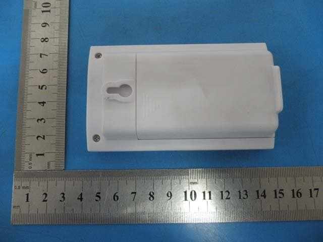
Click to zoom
Application Details
- Equipment Class
- DTS - Digital Transmission System
- Date of Grant
- Oct 21, 2014
- Application Purpose
- Original Equipment
- Date of Application
- Oct 21, 2014
- Equipment Note
- Wireless Bluetooth Thermometer
- Frequency Range
- 2402.00000000 - 2480.00000000
- Company
- SEVEN LIKE CO., LIMITED
- Country
- China
Documents & Files
Document Text
Text extracted from the exhibit documents filed with the FCC. Open a document above to read the original.
Users Manual
Sensorblue WO208 Blue Tooth Hygro-thermometer NS-WSTB01 UNIT & LCD 1. LCD display 2. LED indications light 3. Sensor holes 4. Wall hanger 5. Battery compartment 6. Reset 7. Unit change (F/C) 8Temperature 9. Humidity 10. Connected 11. Battery status . 8 9 27.8 36 % C 10 11 1 2 3 4 5 7 6 1.GETTING STARTED 1. Slide back the battery cover and insert 3xAAA 1.5V batteries according to the polarities indicated. 2. Slide back the battery cover. The LED indication light is no flashing red/blue. 2 . DOWNLOAD THE APPLICATION AND CONNECT WITH SENSORBLUE. 1. On your smart device download either on Google's® Play Store or Apple's® App Store the APP Sensorblue®. 2. Open the application and make sure your Bluetooth is switched on. 3. If the batteries are installed correct and the LED light is flashing red/blue the Sensorblue and the application will connect automatically within seconds. + - + - + - 3. MOUNTING SENSORBLUE: Sensorblue is designed for hanging free on a flat surface. 1. Find the place you want Sensorblue to measure the temperature and humitdity. 2. Insert a nail or screw with a head smaller than Ø 7mm 3. Mount sensorblue on the Wall hanger (4) If sensorblue can not be mounted on a wall, make sure it is lying on its back side to the best possible airflow for correct readings. Note: You do not need to pair with Sensorblue manually, simply open the app and rest is automatic. 4. HOW TO CONNECT MULTIPLE SENSORS: Simply follow the above steps. The application will automatically assign a channel (up to 4) and remember that channel, unless the device is reset. 5.LOW BATTERY: When the sensor is running low on battery, the LED light indication will flash red. The actual status of the battery can also be viewed in the application on your smart device. TROUBLESHOOTING: My device will not connect with sensorblue! - Make sure you device is BLE compatible and has iOS 6+ or Android 4.3 installed. - Make sure your Bluetooth connection is turned on, on your smart device. - Smart device and Sensorblue has to be within 10 meter of each other. My device was connected but can't reconnect. - Make sure Sensorblue has sufficient battery power and both the LCD and LED light is on and flashing. - Make sure your Bluetooth connection is turned on, on your smart device. - Smart device and Sensorblue has to be within 10 meter of each other. - If connection is not possible, remove battery cover and press the reset button (6) - Sensorblue will now return to pairing mode, and you need follow step 2. I think Sensorblue is not measuring correct - In order for sensor blue to measure the actual room / area's temperature and humidity, make sure the sensor is free from any obstacles and hanging freely with it's sensor holes (3) uncovered and in the direction of the room / area measuring area. - Make sure sensorblue is NOT standing, so it covers it's sensor holes (3) - Always allow Sensorblue 30-60min to adjust itself to a new environment. SOFTWARE MANUAL: Choose your units. Confirm with DONE. Tap either Temperature or Humidity to see the history 1/2/3/4 indicates the active sensors. Name of Sensors can be changed in settings. See the Minimum/ Maximum/Average Dew/ Frost Point Temperature or Humidity Tap Dew Point to change to Frost Point Slide to see a full 48 hour history of your Sensor's recording Set your entire alert here. Tap to set value. On/Off on right side. See how much battery is left in your Sensors. Set your language. Set the Sound. Change the Sensors Name Share directly on Social Media See where, which sensor is located. Share on Facebook and Twitter Sensorblue WO208 DE UNIT & LCD 1. LCD-Display 2. LED-Anzeigeleuchten 3. Sensorlöcher 4. Wandaufhänger 5. Batteriefach 6. Reset 7. Einheitwechseln (F/C) 8. Temperatur 9. Luftfeuchtigkeit 10. Verbindungsanzeige 11. Batterieanzeige 8 9 27.8 36 % C 10 11 1 2 3 4 5 7 6 1. ERSTESCHRITTE 1. Öffnen Sie das Batteriefach und legen Sie 3 x AAA 1,5V Batterien der Polarität nach ein. 2. Schließen Sie das Batteriefach. Das LED-Anzeigelicht blinkt jetzt rot/blau. 2 . LADEN SIE DEN APP HERUNTER UND VERBINDEN SIE MIT SENSORBLUE 1. Laden Sie mit Ihrem Smart Device die App Sensorblue® entweder aus Googles® Play Store oder Apples® App Store herunter. 2. Öffnen Sie die App und stellen Sie sicher, dass Bluetooth aktiviert ist. 3. Wenn die Batterien korrekt eingelegt sind und das LED-Licht rot/blau blinkt, werden Sensorblue und die App automatisch innerhalb weniger Sekunden eine Verbindung erstellen. + - + - + - 3. SENSORBLUE MONTIEREN: Sensorblue ist dafür geeignet, frei an flachen Oberflächen zu hängen. 1. Finden Sie eine Stelle, an der Sie Sensorblue aufhängen wollen, um Temperatur und Luftfeuchtigkeit zu messen. 2. Verwenden Sie eine Schraube oder einen Nagel, deren Kopf kleiner als Ø 7mm ist. 3. Hängen Sie Sensorblue an den Wandaufhängern auf (4) Wenn Sensorblue nicht an einer Wand befestigt werden kann, sollten Sie sicherstellen, dass das Gerät auf dem Rücken liegt, damit essich für die korrekte Messung im bestmöglichen Luftstrom befindet. Hinweis: Es ist nicht notwendig, eine manuelle Verbindung mit Sensorblue herzustellen. Öffnen Sie einfach die App und der Rest geschieht automatisch. 4. MEHRERE SENSOREN MITEINANDER VERBINDEN: Befolgen Sie einfach die oben angegebenen Schritte. Die App wird automatisch einen Kanal zuweisen (bis zu vier Kanälen) und diesen erinnern, es sei denn, das Gerät wird neu eingestellt. 5. SCHWACHEBATTERIE: Wenn die Batterie des Sensors schwach ist, wird das LED-Anzeigelicht rot aufleuchten. Der aktuelle Status der Batterie kann auch mithilfe der App auf Ihrem Smart Device kontrolliert werden. FEHLERBEHEBUNG: Mein Gerät stellt keine Verbindung zu Sensorblue her - Stellen Sie sicher, dass Ihr Gerät BLE-kompatibel ist und iOS6+ oder Android 4.3 darauf installiert ist. - Stellen Sie sicher, dass die Bluetooth-Verbindung auf Ihrem Smart Device eingeschaltet ist. - Smart Device und Sensorblue dürfen nicht mehr als 10 Meter voneinander entfernt sein. Mein Gerät war verb…
Text truncated - open the document above for the full version.
Cover Letter(s)
SEVEN LIKE CO., LIMITED Date: 17.10.2014 Authority to Act as an Agent We declare that the following representative (agent) Name Mark Zhu Position General Manager Company Name Alpha Product Testing Laboratory Address Building B, East Area of Nanchang Second Industrial Zone, Gushu 2nd Road, B ao'anDistrict, Shenzhen 518126,P.R.China Tel / Fax 0086-755-86375552/0086-755-26736857 Email [email protected] to act on our behalf on all matters concerning the application and documents submitted to PHOENIX TEST-LAB for product certification below Product Name Blue Tooth Hygro-thermometer Model Name NS-WSTB01 Brand Name N/A Yours sincerely, Signatory Name Seven Wu Position Manager Company Name SEVEN LIKE CO., LIMITED Address RM3128, Nanguang Jiejia Bldg., Futian District, Shenzhen, Guangdong, P.R.C. Tel 0755-28582806 Fax 0755-28582806 Email [email protected] In case of FCC, we certify that we are not subject to a denial of Federal benefits, that include FCC benefits, pursuant to Section 5301 of the Anti-Drug Abuse Act of 1988, 21 U.S.C. §862 because of a conviction for possession or distribution of a controlled substance.
Cover Letter(s)
SEVEN LIKE CO., LIMITED Federal Communications Commission Equipment Authorization Branch 7435 Oakland Mills Road Columbia, MD 21046 Request for Confidentiality Company name: SEVEN LIKE CO., LIMITED FCC ID : 2ACD3-WSTB01 FCC Part 15 Certification Gentlemen, Pursuant to 47 CFR 0.457(d)(1)(ii) and 0.459 we hereby requests permanent confidentiality of the following documents for the subject application: Exhibit Type Description ☒ Schematics All circuitry of devices and component values ☒ Block Diagrams Details of device showing the frequency of all oscillators ☒ Operational Description Description of the circuit functions Note: Exhibit types that are commonly held confidential are: (1) Schematics, (2) Block Diagrams, (3) Bill Of Materials, (4) Operational Descriptions. Any exhibit NOT granted confidentiality is viewable on the FCC website as soon as a grant is issued. These documents contain detailed system and equipment description and related information about the product which we considers to be proprietary, confidential and a custom design and otherwise would not release to the general public. Since the design is a basis from which future technological products will evolve, we consider that this information would be of benefit to its competitors and that the disclosure of the information in these documents would give competitors an unfair advantage in the market. Yours sincerely, Signatory Name Seven Wu Position Manager Company Name SEVEN LIKE CO., LIMITED Address RM3128, Nanguang Jiejia Bldg., Futian District, Shenzhen, Guangdong, P.R.C. Tel 0755-28582806 Fax 0755-28582806 Email [email protected]
ID Label/Location Info
25mm 8mm FCC ID: 2ACD3-WSTB01
ID Label/Location Info
Label location
Internal Photos
ANTENNA
Test Report
TEST REPORT FCC ID:2ACD3-WSTB01 Applicant : SEVEN LIKE CO., LIMITED Address : RM3128,Nan guang Jiejia Bldg., Futian District, Shenzhen, Guangdong, P.R.C. Equipment Under Test (EUT): Name : Blue Tooth Hygro-thermometer Model : NS-WSTB01, AOK-2033 Standards : FCC PART 15, SUBPART C : 2013 (Section 15.247) Report No : T1840015 01 Date of Test : October 10- 16, 2014 Date of Issue : October 17, 2014 Ts e t R e s u l t : PASS In the configuration tested, the EUT complied with the standards specified above Authorized Signature (Mark Zhu) General Manager The manufacture should ensure that all the products in series production are in conformity with the product sample detailed in this report. If the product in this report is used in any configuration other than that detailed in the report, the manufacturer must ensure the new system complies with all relevant standards. Any mention of Alpha Product Testing Laboratory Or test done by Alpha Product Testing Laboratory Approvals in connection with, distribution or use of the product described in this report must be approved by Alpha Product Testing Laboratory Approvals in writing. Page 2 of 36 T1840015 01 TABLE OF CONTENT 1 General Information ------------------------------------------------------------------------------------- 3 1.1 Description of Device (EUT) --------------------------------------------------------------------- 3 1.2 Description of Test Facility ----------------------------------------------------------------------- 3 2 EMC Equipment List ------------------------------------------------------------------------------------ 4 3 Test Procedure --------------------------------------------------------------------------------------------- 5 4 Summary of Measurement ----------------------------------------------------------------------------- 6 4.1 Summary of test result ---------------------------------------------------------------------------- 6 4.2 Test connection ------------------------------------------------------------------------------------- 6 4.3 Assistant equipment used for test ---------------------------------------------------------------- 7 4.4 Test mode ------------------------------------------------------------------------------------------- 7 4.5 Test Conditions ------------------------------------------------------------------------------------- 7 4.6 Measurement Uncertainty (95% confidence levels, k=2)------------------------------------- 7 5 Spurious Emission ---------------------------------------------------------------------------------------- 8 5.1 Radiation Emission -------------------------------------------------------------------------------- 8 6 POWER LINE CONDUCTED EMISSION ------------------------------------------------------ 16 6.1 Conducted Emission Limits(15.207) ---------------------------------------------------------- 16 6.2 Test Setup ----------------------------------------------------------------------------------------- 16 6.3 Test Procedure ------------------------------------------------------------------------------------ 17 6.4 Test Results --------------------------------------------------------------------------------------- 17 7 Conducted Maximum Output Power--------------------------------------------------------------- 18 7.1 Test limit ------------------------------------------------------------------------------------------ 18 7.2 Test Procedure ------------------------------------------------------------------------------------ 18 7.3 Test Setup ----------------------------------------------------------------------------------------- 18 7.4 Test Results --------------------------------------------------------------------------------------- 18 8 PEAK POWER SPECTRAL DENSITY ---------------------------------------------------------- 19 8.1 Test limit ------------------------------------------------------------------------------------------ 19 8.2 Method of measurement ------------------------------------------------------------------------ 19 8.3 Test Setup ----------------------------------------------------------------------------------------- 19 8.4 Test Results --------------------------------------------------------------------------------------- 19 9 Bandwidth ----------------------------------------------------------------------------------------------- 22 9.1 Test limit ------------------------------------------------------------------------------------------ 22 9.2 Method of measurement ------------------------------------------------------------------------ 22 9.3 Test Setup ----------------------------------------------------------------------------------------- 22 9.4 Test Results --------------------------------------------------------------------------------------- 22 10 Band Edge Check -------------------------------------------------------------------------------------- 25 10.1 Test limit ------------------------------------------------------------------------------------------ 25 10.2 Test Procedure ------------------------------------------------------------------------------------ 25 10.3 Test Setup ----------------------------------------------------------------------------------------- 25 10.4 Test Result ---------------------------------------------------------------------------------------- 25 11 Antenna Requirement --------------------------------------------------------------------------------- 30 11.1 Standard Requirement --------------------------------------------------------------------------- 30 11.2 Antenna Connected Construction -------------------------------------------------------------- 30 11.3 Result ---------------------------------------------------------------------------------------------- 30 12 Photographs of Test Setup ---------------------------------------------------------------------------- 31 13 Photographs of EUT ----------------------------------------------------------------------------------- 32 Page 3 of 36 T1840015 01 1 General Inf…
Text truncated - open the document above for the full version.
Test Setup Photos
Radiated Emission Test Setup in Chamber
Contact Information
Applicant
SEVEN Wu
Test Firm
Shenzhen Alpha Product Testing Co., Ltd.Mark Zhu
Technical Specifications
| # | Rule Parts | Frequency Range | Power Output |
|---|---|---|---|
| 1 | 15C | 2.40 GHz - 2.48 GHz | 1.00 mW |
Other Applications from SEVEN LIKE CO., LIMITED

2ACD3-WS08
Aug 19, 2020Smart Hygrometer
Equipment Class
DTS - Digital Transmission System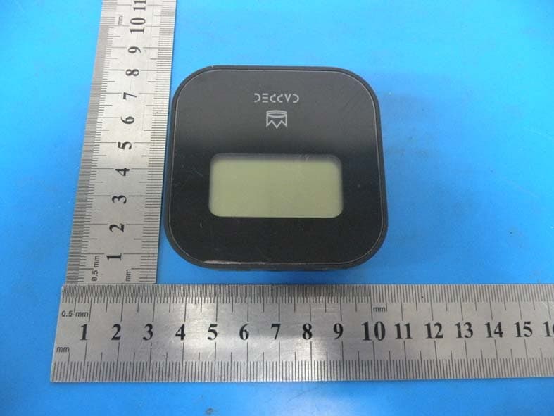
2ACD3-BTH01
May 12, 2014Wireless Bluetooth Thermometer
Equipment Class
DTS - Digital Transmission System