2ACHUEK20HWLAN IP CAM
BAYCOM OPTO-ELECTRONICS TECHNOLOGY CO., LTD.
Click to zoom
Application Details
- Equipment Class
- DTS - Digital Transmission System
- Date of Grant
- Dec 23, 2015
- Application Purpose
- Original Equipment
- Date of Application
- Dec 21, 2015
- Equipment Note
- WLAN IP CAM
- Frequency Range
- 2412.00000000 - 2462.00000000
- Country
- Taiwan
Documents & Files
Document Text
Text extracted from the exhibit documents filed with the FCC. Open a document above to read the original.
Users Manual
1. Lens 2. IR LED (Night vision function) 3. Network LED Indicator 4. Power LED indicator 5. Built-in Microphone 6. Speaker inside 7. PIR Sensor (Optional) 1 2 3 7 5 4 1. Package Contents Camera / Mounting Bracket / AC Power Adapter / Mounting Screws / Quick Installation Guide 2. Physical Descriptions HD IP Camera 3. Network Requirements - An ADSL modem with Internet connection. - A broadband router, preferably with Wi-Fi capability. Please make sure DHCP is enabled on your router. Wi-Fi P/N:2IGOK20H0111 4. Install the hardware and connect with PC Before connect camera to the Internet, please check if your router has a WPS button, and then follow the WPS setup. If not (or unsure), please follow the wire setup. A. Wired setup a. Connect a network cable to the network port, which is on the back of Camera and a LAN port of the router. b. Then plug the power adapter of Camera to power on the camera. C. Viewing camera video image through I.E. Browser K20H Series Front View Side View 13. Audio jack (Optional) 14. Micro SD Card Slot 13 14 8. Camera UID (Optional) 9. RJ-45 Network port 10. WPS button 11. DC5V-IN Socket 12. Reset button b. Click Computer c. Click network icon, then double click the UCAM (xx.xx.xx.xx.xx.xx)(xx.xx.xx.xx), Windows will automatically open the browser (please select IE browser). 5VDC Power Ethernet Cable ADSL Router Push WPS button on the router and camera ADSL Router 5VDC Power b. Press the WPS button (on the lower back of Camera) for 4 seconds until its LED blinks. Then press the WPS button on your router and wait for the Wi-Fi connection to be established (within 10 to 120 seconds). B. Wireless setup via WPS NotePlease unplug the network cable for Camera WPS setup. a. Plug the power adapter and power on your Camera then wait for 40 seconds to boot the camera (operating system). Quick Installation Guide Back View 8 9 11 12 10 a. In order to successfully install the camera, make sure you have these followings: - DHCP is enabled on your Wi-Fi router. - Please link to the below hyperlink to download and Install the Plug-in le in your PC. (http://www.ucamsee.com/webe/html/news/02. php?num=33&page=1&kind=8) - Make sure your camera and PC in the same network segment. 6 Baycom K20H(K20,K20S,K20K) 6. Frequently Asked Questions A. How to move your Camera to a new environment Wired modeRemove the power adapter of Camera & follow the Wired setup of step 2. Wi-Fi modeRemove the power adapter of Camera and follow the Wi-Fi setup of step 2. C. Camera can support up to 32GB (FAT32) Micro SD Card for recording storage. B. If you are still having di culty, you may attempt to perform a factory reset on your Camera. With the power on, press the RESET button on the back of your Camera for 10 seconds and then proceed to setup your camera from the beginning again. E. The maximum recording time of 32GB Micro SD Card is 71 hours (about 2.9 days) with the highest resolution. F. LED indicator & Speaker de nition: Wall Mount Guidance 1:1 D. If still can’t get the live video image via IE browser. How can I do? Please remove Plug-in le then download and install it again. 65mm 75mm 20mm d. Enter your Username and Password to log-in to the IP camera. (Default is admin / 888888) e. You will get the Live Video Image. f. For further advanced setting, please click x tool to adjust the detail parameters. c: Open ”Smart-cam” and “Click here to add camera” by scanning QR code on the back of Camera to get the UID. d: Enter Password (default 888888) then press OK to add your camera. e: Once you have seen the status of your Camera is Online and then you can and watch the live video right away. 5. IP Camera Connection via P2P (Optional): a: Download APP “Smart-Cam” from Google Play / Apple Store or scan QR code to install it. b: Download “Barcode Scanner” to scan UID from Google Play or Apple Store. Android iOS No.Cata Power LED Orange color Network LED Green color Speaker 1Camera Initialize------ 2Network ConnectionON--- 3WPS EnableFlash--- 4AP ModeSlow Flash--- 5Reset to Default---3 Beeps Sound 6Start to upgrade new Firmware ---1 Beeps Sound 7Firmware upgrade on-goingFast Flash--- ON FCC Compliance and Advisory Statement This equipment has been tested and found to comply with the limits for a Class B digital device, pursuant to part 15 of the FCC rules. These limits are designed to provide reasonable protection against harmful interference in a residential installation. This equipment generates, uses and can radiate radio frequency energy and, if not installed and used in accordance with the instructions, may cause harmful interfer- ence to radio communications. However, there is no guaran- tee that interference will not occur in a particular installation. If this equipment does cause harmful interference to radio or television reception, which can be determined by turning the equipment o and on, the user is encouraged to try to correct the interference by one or more of the following measures: - Reorient or relocate the receiving antenna. - Increase the separation between the equipment and receiver. - Connect the equipment into an outlet on a circuit di erent from that to which the receiver is connected. - Consult the dealer or an experienced radion/TV technician for help. Any changes or modi cations not expressly approved by the party responsible for compliance could void the user's authority to operate this equipment. FCC RF Radiation Exposure Statement: 1. This Transmitter must not be co‐located or operating in conjunction with any other antenna or transmitter. 2. This equipment complies with FCC RF radiation exposure limits set forth for an uncontrolled environment. This equipment should be installed and operated with a minimum distance of 20 centimeters between the radiator and your body. G. Please power o your camera and pull the adapter before you insert the SD card to make sure the recording video les can well storage.
External Photos
External photo of EUT External photo of EUT External photo of EUT
Internal Photos
Internal photo of EUT Internal photo of EUT Internal photo of EUT RF Module Antenna 1 Internal photo of EUT Antenna 2
RF Exposure Info
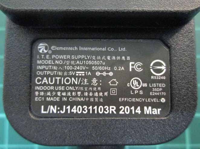
FCC ID: 2ACHUEK20H Report No.: 150900216TWN-001 Page 1 of 12 0597 Maximum Permissible Exposure (MPE) Evaluation Report Report No. : 150200219TWN-001 Model No. : K20H(K20, K20S, K20K) Issued Date : Nov. 11, 2015 Applicant: Baycom Opto-Electronics Technology Co., Ltd. 1F, No. 9, Industrial East 9 th Rd, Hsinchu Science Park, Hsin Chu City, Taiwan Test Method/ Standard: FCC 1.1310 Test By: Intertek Testing Services Taiwan Ltd. No. 11, Lane 275, Ko-Nan 1 Street, Chia-Tung Li, Shiang-Shan District, Hsinchu City, Taiwan It may be duplicated completely for legal use with the allowance of the applicant. It shall not be reproduced except in full, without the written approval of Intertek Laboratory. The test result(s) in this report only applies to the tested sample(s). The test report was prepared by: Freda Huang/ Assistant These measurements were taken by: Ricky Lee/ Engineer The test report was reviewed by: Name Jimmy Yang Title Senior Engineer FCC ID: 2ACHUEK20H Report No.: 150900216TWN-001 Page 2 of 12 Revision History Report No. Issue Date Revision Summary 150900216TWN-001Nov. 11, 2015 Original report. FCC ID: 2ACHUEK20H Report No.: 150900216TWN-001 Page 3 of 12 Table of Contents Summary of Tests ..............................................................................................................4 1. General information ......................................................................................................5 1.1 Identification of the EUT ........................................................................................5 1.2 Additional information about the EUT....................................................................6 1.3 Antenna description.................................................................................................6 2. Test specifications .........................................................................................................7 2.1 Introduction .............................................................................................................7 2.2 RF Exposure Limit ..................................................................................................8 2.3 RF Exposure calculations......................................................................................10 2.4 Operation mode .....................................................................................................10 2.5 Test equipment ......................................................................................................10 2.6 Test Set-up .............................................................................................................11 3. Test results ...................................................................................................................12 FCC ID: 2ACHUEK20H Report No.: 150900216TWN-001 Page 4 of 12 Summary of Tests MPE Evaluation meet FCC OET No. 65: 1997, IEEE C95.1-2005 Test Reference Results MPE Evaluation FCC Guidelines for Human Exposure IEEE C95.1Complies FCC ID: 2ACHUEK20H Report No.: 150900216TWN-001 Page 5 of 12 1. General information 1.1 Identification of the EUT Product: WLAN IP CAM Model No: K20H(K20, K20S, K20K) Brand Name: Baycom FCC ID: 2ACHUEK20H Manufacturer: QUN-DA TECHNONLOGY CO.,LTD Address: No. 154-2 Yuanpei Street, Hsinchu, Taiwan Operating Frequency: 1. 2412 MHz ~ 2462 MHz for 802.11b, 802.11g, 802.11n HT20 2. 2422 MHz ~ 2452 MHz for 802.11n HT40 Channel Number: 11 channels for 2412 MHz ~ 2462 MHz 7 channels for 2422 MHz ~ 2452 MHz Frequency of Each Channel: 2412+5 k, k=0 ~ 10 for 802.11b, 802.11g, 802.11n HT20 Access scheme: DSSS, OFDM Rated Power: DC 5 V from adapter Power Cord: N/A Sample Received: Sep. 09, 2015 Test Date(s): Nov. 03, 2015 Note 1: This report is for the exclusive use of Intertek's Client and is provided pursuant to the agreement between Intertek and its Client. Intertek's responsibility and liability are limited to the terms and conditions of the agreement. Intertek assumes no liability to any party, other than to the Client in accordance with the agreement, for any loss, expense or damage occasioned by the use of this report. Only the Client is authorized to permit copying or distribution of this report and then only in its entirety. Any use of the Intertek name or one of its marks for the sale or advertisement of the tested material, product or service must first be approved in writing by Intertek. The observations and test results in this report are relevant only to the sample tested. This report by itself does not imply that the material, product, or service is or has ever been under an Intertek certification program. Note 2: When determining the test conclusion, the Measurement Uncertainty of test has been considered. FCC ID: 2ACHUEK20H Report No.: 150900216TWN-001 Page 6 of 12 1.2 Adapter information The EUT will be supplied with a power supply from below list: No. Model no. Specification Adapter AU1050507u I/P: 100-240Vac, 50/60Hz, 0.2A O/P: 5Vdc, 1A 1.3 Additional information about the EUT Transmit path Modulation mode Chain 0 / Main Chain 1 / AUX 802.11b V X 802.11g V V 802.11 n (HT20) V V 802.11 n (HT40) V V Product SW version : 1.4.10.27.C Product HW version : ES5 Radio SW version : NA Radio HW version : ES4 1.4 Antenna description The EUT uses a permanently connected antenna. Antenna Gain : 2 dBi Antenna Type : PCB Antenna Connector Type : I-PEX 1.5 Peripherals equipment Peripherals Brand Model No. Serial No. Data cable Notebook PC IBM 1860 L3BTAG6 RJ-45 STP Cat.5 1 meter × 1 Wireless AP BUFFALO WZR-AGL300NH 44000000000000 RJ-45 STP Cat.5 1 meter × 1 FCC ID: 2ACHUEK20H Report No.: 150900216TWN-001 Page 7 of 12 2. Test specifications 2.1 Introduction The EUT operates in the 2.4 GHz ISM band. Due to the EUT (include antenna) at its normal operation distance is at least 20 cm from the human body, the EUT was defined as a Mobile Device. The reason to do the MPE Evaluation is to avoid the RF hazard to human body. The m…
Text truncated - open the document above for the full version.
Test Report
FCC ID: 2ACHUEK20H Report No.: 150900215TWN-001 Page 1 of 83 EMC TEST REPORT Report No. : 150900215TWN-001 Model No. : K20H(K20, K20S, K20K) Issued Date : Nov. 11, 2015 Applicant: Baycom Opto-Electronics Technology Co., Ltd. 1F, No. 9, Industrial East 9 th Rd, Hsinchu Science Park, Hsin Chu City, Taiwan Test Method/ Standard: 47 CFR FCC Part 15.247 & ANSI C63.10 2013 KDB 558074 D01 v03r03 KDB 662911 D01 v02r01 Registration No.: : 93910 Test By: Intertek Testing Services Taiwan Ltd. No. 11, Lane 275, Ko-Nan 1 Street, Chia-Tung Li, Shiang-Shan District, Hsinchu City, Taiwan It may be duplicated completely for legal use with the allowance of the applicant. It shall not be reproduced except in full, without the written approval of Intertek Laboratory. The test result(s) in this report only applies to the tested sample(s). The test report was prepared by: Freda Huang/ Assistant These measurements were taken by: Ricky Lee/ Engineer The test report was reviewed by: Name Jimmy Yang Title Senior Engineer FCC ID: 2ACHUEK20H Report No.: 150900215TWN-001 Page 2 of 83 Revision History Report No. Issue Date Revision Summary 150900215TWN-001 Nov. 11, 2015 Original report. FCC ID: 2ACHUEK20H Report No.: 150900215TWN-001 Page 3 of 83 Table of Contents 1. Summary of Test Data................................................................................................................. 5 2. General Information.................................................................................................................... 6 2.1 Identification of the EUT ...................................................................................................... 6 2.2 Adapter information .............................................................................................................. 7 2.3 Description of EUT............................................................................................................... 7 2.4 Antenna description .............................................................................................................. 7 2.5 Peripherals equipment........................................................................................................... 8 2.6 Operation mode..................................................................................................................... 8 2.7 Applied test modes and channels ........................................................................................ 10 2.8 Power setting of test software .............................................................................................11 3. Minimum 6 dB Bandwidth ....................................................................................................... 14 3.1 Operating environment ....................................................................................................... 14 3.2 Limit for minimum 6dB bandwidth .................................................................................... 14 3.3 Measuring instrument setting.............................................................................................. 14 3.4 Test procedure ..................................................................................................................... 14 3.5 Test diagram ........................................................................................................................ 15 3.6 Test results........................................................................................................................... 15 4. Maximum Peak Conducted Output Power ............................................................................... 27 4.1 Operating environment ....................................................................................................... 27 4.2 Limit for maximum peak conducted output power............................................................. 27 4.3 Measuring instrument setting.............................................................................................. 27 4.4 Test procedure ..................................................................................................................... 27 4.5 Test diagram ........................................................................................................................ 27 4.6 Test result ............................................................................................................................ 28 5. Power Spectral Density............................................................................................................. 29 5.1 Operating environment ....................................................................................................... 29 5.2 Limit for power spectrum density....................................................................................... 29 5.3 Measuring instrument setting.............................................................................................. 29 5.4 Test procedure ..................................................................................................................... 30 5.5 Test diagram ........................................................................................................................ 30 5.6 Test results........................................................................................................................... 30 6. Emissions In Non-Restricted Frequency Bands ....................................................................... 43 6.1 Operating environment ....................................................................................................... 43 FCC ID: 2ACHUEK20H Report No.: 150900215TWN-001 Page 4 of 83 6.2 Limit for emissions in non-restricted frequency bands....................................................... 43 6.3 Measuring instruments setting ............................................................................................ 43 6.4 Te…
Text truncated - open the document above for the full version.
Test Report
FCC ID: 2ACHUEK20H Report No.: 150900215TWN-001 Page 43 of 83 6. Emissions In Non-Restricted Frequency Bands 6.1 Operating environment Temperature: 25 °C Relative Humidity: 50 % Atmospheric Pressure 1008 hPa Requirement 15.247(d) Channel number 1、6、11 6.2 Limit for emissions in non-restricted frequency bands The peak output power measured in any 100 kHz bandwidth outside of the authorized frequency band shall be attenuated by at least 20 dB relative to the maximum in-band peak PSD level in 100 kHz 6.3 Measuring instruments setting Reference level measurement Spectrum analyzer settings Spectrum Analyzer function Setting Detector Peak RBW ≧100 kHz VBW ≧3 x RBW Sweep Auto couple Trace Max hold Span ≧1.5 time 6dB bandwidth Attenuation Auto FCC ID: 2ACHUEK20H Report No.: 150900215TWN-001 Page 44 of 83 Emission level measurement Spectrum analyzer settings Spectrum Analyzer function Setting Detector Peak RBW ≧100 kHz VBW ≧3 x RBW Sweep Auto couple Trace Max hold Attenuation Auto 6.4 Test procedure 1. The procedure was used in antenna-port conducted and connected to the spectrum analyzer. 2. Set instrument center frequency to center frequency 3. Use the parameter configured in clause 6.3 to measure 4. Use the peak marker function to determine the maximum amplitude level. 6.5 Test diagram 6.6 Test results Spectrum Analyzer Attenuator & DC block Power supply EUT FCC ID: 2ACHUEK20H Report No.: 150900215TWN-001 Page 45 of 83 Chain0 : Conducted Spurious @ 802.11b mode Ch 1 Chain0 : Conducted Spurious @ 802.11b mode Ch 1 FCC ID: 2ACHUEK20H Report No.: 150900215TWN-001 Page 46 of 83 Chain0 : Conducted Spurious @ 802.11b mode ch11 Chain0 : Conducted Spurious @ 802.11b mode ch11 FCC ID: 2ACHUEK20H Report No.: 150900215TWN-001 Page 47 of 83 Chain0 : Conducted Spurious @ 802.11b mode ch6 Chain0 : Conducted Spurious @ 802.11b mode ch6 FCC ID: 2ACHUEK20H Report No.: 150900215TWN-001 Page 48 of 83 Chain0 : Conducted Spurious @ 802.11g mode ch11 Chain0 : Conducted Spurious @ 802.11g mode ch11 FCC ID: 2ACHUEK20H Report No.: 150900215TWN-001 Page 49 of 83 Chain0 : Conducted Spurious @ 802.11g mode ch1 Chain0 : Conducted Spurious @ 802.11g mode ch1 FCC ID: 2ACHUEK20H Report No.: 150900215TWN-001 Page 50 of 83 Chain0 : Conducted Spurious @ 802.11g mode ch6 Chain0 : Conducted Spurious @ 802.11g mode ch6 FCC ID: 2ACHUEK20H Report No.: 150900215TWN-001 Page 51 of 83 Chain1 : Conducted Spurious @ 802.11g mode ch11 Chain1 : Conducted Spurious @ 802.11g mode ch11 FCC ID: 2ACHUEK20H Report No.: 150900215TWN-001 Page 52 of 83 Chain1 : Conducted Spurious @ 802.11g mode ch1 Chain1 : Conducted Spurious @ 802.11g mode ch1 FCC ID: 2ACHUEK20H Report No.: 150900215TWN-001 Page 53 of 83 Chain1 : Conducted Spurious @ 802.11g mode ch6 Chain1 : Conducted Spurious @ 802.11g mode ch6 FCC ID: 2ACHUEK20H Report No.: 150900215TWN-001 Page 54 of 83 Chain0 : Conducted Spurious @ 802.11n(HT20) mode ch11 Chain0 : Conducted Spurious @ 802.11n(HT20) mode ch11 FCC ID: 2ACHUEK20H Report No.: 150900215TWN-001 Page 55 of 83 Chain0 : Conducted Spurious @ 802.11n(HT20) mode ch1 Chain0 : Conducted Spurious @ 802.11n(HT20) mode ch1 FCC ID: 2ACHUEK20H Report No.: 150900215TWN-001 Page 56 of 83 Chain0 : Conducted Spurious @ 802.11n(HT20) mode ch6 Chain0 : Conducted Spurious @ 802.11n(HT20) mode ch6 FCC ID: 2ACHUEK20H Report No.: 150900215TWN-001 Page 57 of 83 Chain1 : Conducted Spurious @ 802.11n(HT20) mode ch11 Chain1 : Conducted Spurious @ 802.11n(HT20) mode ch11 FCC ID: 2ACHUEK20H Report No.: 150900215TWN-001 Page 58 of 83 Chain1 : Conducted Spurious @ 802.11n(HT20) mode ch1 Chain1 : Conducted Spurious @ 802.11n(HT20) mode ch1 FCC ID: 2ACHUEK20H Report No.: 150900215TWN-001 Page 59 of 83 Chain1 : Conducted Spurious @ 802.11n(HT20) mode ch6 Chain1 : Conducted Spurious @ 802.11n(HT20) mode ch6 FCC ID: 2ACHUEK20H Report No.: 150900215TWN-001 Page 60 of 83 Chain0 : Conducted Spurious @ 802.11n(HT40) mode ch3 Chain0 : Conducted Spurious @ 802.11n(HT40) mode ch3 FCC ID: 2ACHUEK20H Report No.: 150900215TWN-001 Page 61 of 83 Chain0 : Conducted Spurious @ 802.11n(HT40) mode ch6 Chain0 : Conducted Spurious @ 802.11n(HT40) mode ch6 FCC ID: 2ACHUEK20H Report No.: 150900215TWN-001 Page 62 of 83 Chain0 : Conducted Spurious @ 802.11n(HT40) mode ch9 Chain0 : Conducted Spurious @ 802.11n(HT40) mode ch9 FCC ID: 2ACHUEK20H Report No.: 150900215TWN-001 Page 63 of 83 Chain1 : Conducted Spurious @ 802.11n(HT40) mode ch3 Chain1 : Conducted Spurious @ 802.11n(HT40) mode ch3 FCC ID: 2ACHUEK20H Report No.: 150900215TWN-001 Page 64 of 83 Chain1 : Conducted Spurious @ 802.11n(HT40) mode ch6 Chain1 : Conducted Spurious @ 802.11n(HT40) mode ch6 FCC ID: 2ACHUEK20H Report No.: 150900215TWN-001 Page 65 of 83 Chain1 : Conducted Spurious @ 802.11n(HT40) mode ch9 Chain1 : Conducted Spurious @ 802.11n(HT40) mode ch9 FCC ID: 2ACHUEK20H Report No.: 150900215TWN-001 Page 66 of 83 7. Emissions In Restricted Frequency Bands (Radiated emission measurements) 7.1 Operating environment Temperature: 25 °C Relative Humidity: 50 % Atmospheric Pressure 1008 hPa Requirement 15.247(d), 15.205, 15.209 7.2 Limit for emission in restricted frequency bands (Radiated emission measurement) Frequency (MHz) Field Strength (microvolts/meter) Measurement distance (meters) 0.009~0.490 2400/F(kHz) 300 0.490~1.705 2400/F(kHz) 30 1.705~30 30 30 30-88 100 3 88-216 150 3 216-960 200 3 Above 960 500 3 Remark: 1. In the above table, the tighter limit applies at the band edges. 2. Distance refers to the distance in meters between the measuring instrument antenna and the closed point of any part of the device or system FCC ID: 2ACHUEK20H Report No.: 150900215TWN-001 Page 67 of 83 7.3 Measuring instrument setting Below 1GHz measurement Receiver settings Receiver function Setting Detector QP RBW 9-150 kHz ; 200-300 Hz 0.15-30 MHz; 9-10 kHz 30-1000 MHz; 100-120 kHz VBW ≧3 x RBW Sweep Auto couple Attenuation Auto Above 1GHz measurement Spectrum analyzer settings Spectrum Analyzer function Setting Detector Peak RBW 1MHz VBW 3…
Text truncated - open the document above for the full version.
Test Setup Photos
Conducted Emission Test set-up photo
Test Setup Photos
Radiated Emission Test set-up photo 9kHz- 30MHz Radiated Emission Test set-up photo Below 1GHz Radiated Emission Test set-up photo Above 1GHz
Contact Information
Applicant
Donald Huang(General Manager)
Technical Contact
Test Firm
Intertek Testing Services Taiwan Ltd.Lily Shih
Technical Specifications
| # | Rule Parts | Frequency Range | Power Output |
|---|---|---|---|
| 1 | 15C | 2.41 GHz - 2.46 GHz | 271.00 mW |
Other Applications from BAYCOM OPTO-ELECTRONICS TECHNOLOGY CO., LTD.
2ACHUEK10H
Jun 19, 2014Wireless Network IP Camera
Equipment Class
DTS - Digital Transmission System