2ACIG-9751USTX15THE ELF LIGHT REMOTE CONTROL
LF Products Pte Ltd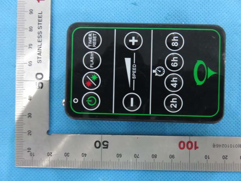
Click to zoom
Application Details
- Equipment Class
- DSC - Part 15 Security/Remote Control Transmitter
- Date of Grant
- May 25, 2015
- Application Purpose
- Original Equipment
- Date of Application
- May 25, 2015
- Equipment Note
- THE ELF LIGHT REMOTE CONTROL
- Frequency Range
- 433.92000000 - 433.92000000
- Company
- LF Products Pte Ltd
- Country
- Singapore
Documents & Files
Document Text
Text extracted from the exhibit documents filed with the FCC. Open a document above to read the original.
Users Manual
WARNING: Use provided transformer only. LASER RADIATION AVOID DIRECT EYE EXPOSURE CLASS IIIa LASER PRODUCT Diode Laser Max : Output < 5mW Wavelength 532nm~660nm USER’S GUIDE (READ ME FIRST) SPEED 2 h 4 h 6 h 8 h TIMER RESET FLASH Thank you for your purchase of the Elf Light™. Enjoy! TM the Original www.technosourceusa.com A Division of LF Products The manufacturer warrants this product to be free from defects in functionality, materials and workmanship for a period of one (1) year from date of purchase. This warranty applies only to the original consumer purchaser and only to products used in normal use and service. If this product is found to be defective, the manufacturer’s only obligation, and your exclusive remedy, is the repair or replacement of the product at the manufacturer’s discretion, provided that the product has not been damaged through misuse, abuse, accident, modifications, alterations, neglect or mishandling. This warranty shall not apply to any product that is found to have been improperly installed, set up, or used in any way not in accordance with the instructions supplied with the product. This warranty shall not apply to a failure of the product as a result of an accident, misuse, abuse, negligence, alteration, or faulty installation, or any other failure not relating to faulty material or workmanship. This warranty shall not apply to the finish on any portion of the product, such as surface and/or weathering, as this is considered normal wear and tear. The manufacturer does not warrant and specially disclaims any warranty, whether expressed or implied, of fitness for a particular purpose, other than the warranty contained herein. The manufacturer specifically disclaims any liability and shall not be liable for any consequential or incidental loss of damage, including any labor/ex- pense costs involved in the replacement or repair of said product. For warranty claims, please contact Techno Source at pat@technosourceu- sa.com or write to Techno Source Pat Johnson 20 W 22nd Street, New York, NY 10010 Product Specifications Laser Classification / Power Laser Wavelength(s) Laser Diode Life Power Consumption Power Input Operating Environment Projection Coverage Maintenance Warranty Limited one year warranty Maintenance Free – No user serviceable parts Indoor / Outdoor; -15º F to 90º F 120VAC (When used with manufacturer provided transformer) Up to 5 watts @ 65ºF - 90ºF About 7000 hours (at 4hrs per day) 532nm (Green) / 660nm (Red) Class IIIa / Less than 5 mW (single beam) Techno Source, A Division of LF Products, © 2015 LF Products, All rights reserved. 800 Cheung Sha Wan Road, Kowloon, Hong Kong. MADE IN CHINA Product specifications and colors may vary Item number: 97516, 97540 10 ft. back, 25 ft x 25 ft (625 ft 2 ) 15 ft. back, 30 ft x 30 ft (900 ft 2 ) 20 ft. back, 35 ft x 35 ft (1,225 ft 2 ) PAGE 8 Please check your state and local laws for outdoor laser usage. Although the Elf Light is generally safe when used responsibly, please exercise the following precautions: Precautions For Laser Usage • Do not aim or shine at people, animals or traffic from land, sea, or air. • Use with caution within 5 nautical miles of an airport. • The Elf Light should always be stationary; do not hold in hand when operating. • Position the Elf Light so that the lights are within the confines of the target object. • Do not use near infants/cribs and keep away from children. IMPORTANT SAFETY INSTRUCTIONS THIS PRODUCT HAS A POLARIZED PLUG (ONE BLADE IS WIDER THAN THE OTHER) AS A FEATURE TO REDUCE THE RISK OF ELECTRIC SHOCK. THIS PLUG WILL FIT IN A POLARIZED OUTLET ONLY ONE WAY. IF THE PLUG DOES NOT FIT FULLY IN THE OUTLET, REVERSE THE PLUG. IF IT STILL DOES NOT FIT, CONTACT A QUALIFIED ELECTRICIAN. NEVER USE WITH AN EXTENSION CORD UNLESS PLUG CAN BE FULLY INSERTED. DO NOT ALTER THE PLUG. However, there is no guarantee that interference will not occur in a particular installation. If this equipment does cause harmful interference to radio or television reception, which can be determined by turning the equipment off and on, the user is encouraged to try to correct the interference by one or more of the following measures: - Reorient or relocate the receiving antenna. - Increase the distance between the equipment and receiver. - Connect the equipment into an outlet on a circuit different from that to which the receiver is connected. - Consult the manufacturer or an experienced radio/TV technician for help. NOTE: This is a standard cautionary statement from the FCC, which is used to alert the user to troubleshoot in various ways if problems are found. Read All Instructions WARNING: When using outdoors, use portable luminaires. Basic safety precautions should always be followed to reduce the risk of fire, electric shock, and personal injury, including the following: a) Use only three-wire outdoor extension cords that have three-prong grounding plugs and grounding receptacles that accept the appliance’s plug. b) Ground Fault Circuit Interrupter (GFCI) protection is to be provided on the circuit(s) or outlet(s) to be used for the wet location portable luminaire. Receptacles are available having built-in GFCI protection and are able to be used for this measure of safety. c) Use only with an extension cord for outdoor use, such as an extension cord of cord type SW, SW-A, SOW, SOW-A, STW, STW-A, STOW, STOW-A, SJW, SJW-A, SJOW, SJOW-A, SJTW, SJTW-A, or SJTOW, SJTOW-A. SAVE THESE INSTRUCTIONS (3)(6) Remote Control Pairing 3. Flash mode – Pressing this button will cycle between steady or flashing lights. For multi-color versions, it will cycle from simultaneous flashing, alternating flashing, single color flashing back to default. • Simultaneous flashing – Both laser colors (if applicable) will flash simultaneously. • Alternating flashing – Both laser colors will alternately flash (multi-color only). Press again and it will default back to simultaneous color (no flashing). 4. Flash speed – Press this to …
Text truncated - open the document above for the full version.
Attestation Statements
Federal Communications Commission Authorization and Evaluation Division Equipment Authorization Branch 7435 Oakland Mills Road Columbia, MD 21046 5/21/2015 To whom it may concern: We, the undersigned, hereby authorize Eurofins Product Service GmbH to act on our behalf in all matters relating to applications for equipment authorization FCC ID: 2ACIG-9751USTX15 including the signing of all documents related to these matters. Any and all acts carried out by Eurofins Product Service GmbH on our behalf shall have the same effect as acts of our own. We also hereby certify that no party to this application is subject to a denial of benefits, including FCC benefits, pursuant to Section 5301 of the Anti-Drug Abuse Act of 1988, 21 U.S.C. 862. Sincerely, Signature LF Products Pte Ltd Contact person: Philip Chiu Title: Engineer Manager
Cover Letter(s)
May 15, 2015 Federal Communication Commission Authorization and Evaluation Division FCC ID: 2ACIG-9751USTX15 Re: Confidentiality Request Pursuant to Sections 0.457 and 0.459 of the Commission’s Rules, the applicant hereby requests confidential treatment of information applied this application as outlined below: 1: Block Diagram 2: Circuit Diagram 3: Parts List 4.Operational Description The above materials contain trade secrets and proprietary information not customarily released to the public. The public disclosure of these matters might be harmful to the applicant and provide unjustified benefits to its competitors. The Applicant understands that pursuant to Rules 0.457, disclosure of this Application and all accompanying documentation will not be made before the date of the Grant for this application. Sincerely, LF Products Pte Ltd Contact person: Philip Chiu Title: Engineer Manager
External Photos
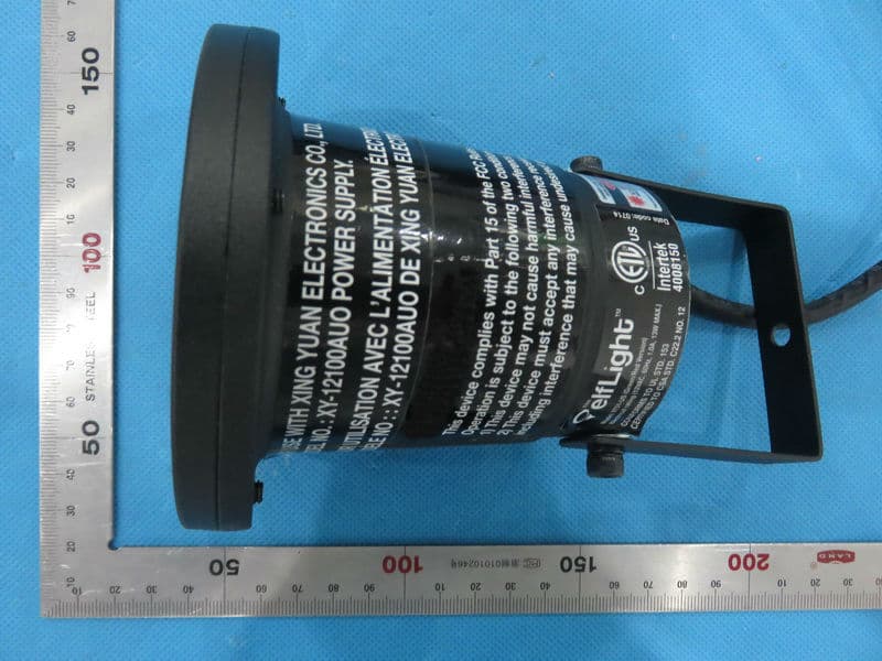
External Photos TOP VIEW OF EUT BOTTOM VIEW OF EUT FRONT VIEW OF EUT BACK VIEW OF EUT LEFT VIEW OF EUT RIGHT VIEW OF EUT
ID Label/Location Info
FCC ID Label Location FCC ID: 2ACIG-9751USTX15
Internal Photos
Internal Photos OPEN VIEW OF EUT-1 INTERNAL VIEW OF EUT-1 INTERNAL VIEW OF EUT-2 INTERNAL VIEW OF EUT-3
Operational Description
Declaration concerning Antenna Specification It is hereby declared that the product Model No.: 9751 FCC ID: 2ACIG-9751USTX15 fulfills the requirement in FCC test relating to the antenna type. The device specified above confirms to the FCC recommendations for internal antenna type described below: Model No. of antenna: N/A Type of antenna: Fixed Antenna Gain of the antenna: 0 dBi Frequency range: 433.92 MHz The mounting of the antenna is fixed to the radio module and no other antenna should be used. Company name: LF Products Pte Ltd Address: 10 Raeburn Park, #03/08 Block A, City: Singapore ZIP / Postal code: 088702 Country: Singapore Place: Shenzhen Date: May 15,2015 Signature:
RF Exposure Info
RF Exposure evaluation Product Description:REMOTE CONTROL Model Number: 9751 FCC ID: 2ACIG-9751USTX15 According to 447498 D01 General RF Exposure Guidance v05 The 1-g and 10-g SAR test exclusion thresholds for 100 MHz to 6 GHz at test separation distances ≤ 50 mm are determined by: [(max. power of channel, including tune-up tolerance, mW)/(min. test separation distance, mm)] ·[√f(GHz)] ≤ 3.0 for 1-g SAR and ≤ 7.5 for 10-g extremity SAR, where f(GHz) is the RF channel transmit frequency in GHz Power and distance are rounded to the nearest mW and mm before calculation According to the follow transmitter output power(P t )formula: P t =(E x d) 2 /(30 x g t ) P t =transmitter output power in watts g t =numeric gain of the transmitting antenna (unitess) E=electric field strength in V/m d=measurement distance in meters (m) According to the above test data, Emax=88.7dBuv/m=0.027V/m,d=3m,g t =1 P t =(E x d) 2 /(30 x g t )=(0.027x3) 2 /(30x1)=0.000218W=0.22mW The result is rounded to one decimal place for comparison Worse case is as below: [433.92MHz -0.22mW output power] (0.22mW /5mm) .[√0.4339(GHz)]= 0.03<3.0 for 1-g SAR Then SAR evaluation is not required NOTE: For the maximum power, you can refer FCC test report.
Test Report
FCC ID APPLI PRODU BRAND MODE CLIEN DATE O STAND REPOR A CAUTI This re test lab D CATION P U UCT DESIG D NAME EL NAME T OF ISSUE DARD(S) RT VERSIO Attestat ION: eport shall boratory an FC Rep URPOSE GNATION ON tion of G not be repr nd shall no C Te port No.: : 2ACI : Origi : THE (GRE : ELF L : 9751 : LF PR : Apr.1 : FCC P : V1.0 Global C roduced ex t be quoted est R AGC0302 IG‐9751UST inal Equipm ELF LIGHT EEN AND R LIGHT 1 RODUCTS P 11, 2015 Part 15 Rul Complia xcept in full d out of con Rep 23150301 TX15 ment T WITH REM RED LIGHT) PTE LTD les ance (Sh l without th ntext. port 1FE03 MOTE CON ) henzhen he written t NTROL & ST n) Co., L permission Page 1 TAND Ltd n of the of 27 AGC03023150301FE03 Page 2 of 27 Report Revise Record Report Version Revise Time Issued Date Valid VersionNotes V1.0 / Apr.11, 2015 Valid Original Report AGC03023150301FE03 Page 3 of 27 TABLE OF CONTENTS 1. VERIFICATION OF CONFORMITY ...................................................................................... 4 2. GENERAL INFORMATION .................................................................................................. 5 2.1. PRODUCT DESCRIPTION ........................................................................................................... 5 2.2. RELATED SUBMITTAL(S) / GRANT (S) ....................................................................................... 5 2.3. TEST METHODOLOGY ................................................................................................................ 5 2.4. SPECIAL ACCESSORIES ............................................................................................................ 5 2.5. EQUIPMENT MODIFICATIONS ................................................................................................... 5 3. MEASUREMENT UNCERTAINTY........................................................................................ 6 4. DESCRIPTION OF TEST MODES ........................................................................................ 6 5. SYSTEM TEST CONFIGURATION ...................................................................................... 6 5.1. EQUIPMENT USED IN EUT SYSTEM ......................................................................................... 6 5.2. SUMMARY OF TEST RESULTS .................................................................................................. 6 6. TEST FACILITY .................................................................................................................... 7 7. ANTENNA REQUIREMENT ................................................................................................. 8 8. PROVISION FOR MOMENTARY OPERATION ................................................................... 9 8.1 MEASUREMENT PROCEDURE ................................................................................................... 9 8.2 TEST SETUP ................................................................................................................................. 9 8.3 TEST RESULT ............................................................................................................................. 10 9. DUTY CYCLE CORRECTION FACTOR ........................................................................................ 11 9.1 MEASUREMENT PROCEDURE ................................................................................................. 11 9.2 TEST SETUP ............................................................................................................................... 11 9.3 TEST RESULT ............................................................................................................................. 12 Test Mode: EUT @ 433.92MHz for RF Transmitter ........................................................................... 12 10. RADIATED EMISSION ..................................................................................................... 15 10.1. MEASUREMENT PROCEDURE .............................................................................................. 15 10.2. TEST SETUP ............................................................................................................................ 17 10.3. TEST RESULT .......................................................................................................................... 18 11. BANDWIDTH .................................................................................................................... 20 11.1. MEASUREMENT PROCEDURE .............................................................................................. 20 11.2. TEST SETUP ............................................................................................................................ 20 11.3. TEST RESULT .......................................................................................................................... 21 APPENDIX A: PHOTOGRAPHS OF TEST SETUP ............................................................... 22 APPENDIX B: PHOTOGRAPHS OF EUT .............................................................................. 23 1 A A M A P B T D D C R W T p g c . VERIFIC Applicant Address Manufacture Address Product Des Brand Name Test Model: Date of test Deviation Condition of Report Temp We hereby ce The above eq rocedures, a iven in ANS ompliance w CATION OF er signation e f Test Samp plate ertify that: quipment wa and equipm SI C63.4 (200 with radiated F CONFOR LF PR 10 RA Max-P No.4 Zhon g THE E LIGHT ELF L 9751 Apr.03 None ple Norm AGCR as tested by ent configur 03) and the d emission li Prepa r Chec k Authori z RMITY RODUCTS P AEBURN PA Plus Co., Ltd Floor, A B gshan City, ELF LIGHT T) LIGHT 3, 2015 to A al RT-US-BR/R y Shenzhen rations show energy emit mits of FCC red By ked By zed By PTE LTD ARK, #03/08 d. uilding, No. Guangdong WITH REM Apr.11, 2015 RF (2013-03 STS Test Se wn in this rep tted by the s C Rules Part Max Z h Kidd Y S…
Text truncated - open the document above for the full version.
Test Setup Photos
APPENDIX IV PHOTOGRAPHS OF TEST SETUP RADIATED EMISSION TEST SETUP
Contact Information
Applicant
Philip Chiu(Engineer Manager)
Test Firm
Shenzhen STS Test Services Co., Ltd.Bovey Yang
Technical Specifications
| # | Rule Parts | Frequency Range | Power Output |
|---|---|---|---|
| 1 | 15.231 | 433.92 MHz - 433.92 MHz | - |
Other Applications from LF Products Pte Ltd
2ACIG-9751USRX15
May 28, 2015THE ELF LIGHT REMOTE CONTROL
Equipment Class
CYY - Communications Receiver used w/Pt 15 Transmitter
2ACIG-9751USRX
Jul 16, 2014Elf Light Green/Red with Remote
Equipment Class
CRR - Superregenerative Receiver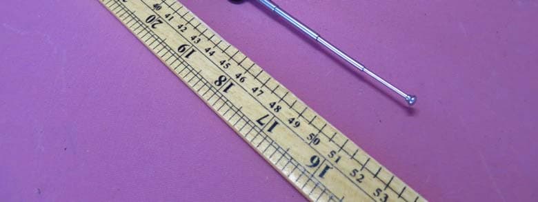
2ACIG-9751USTX
Jul 16, 2014RF Remote Controller
Equipment Class
DSC - Part 15 Security/Remote Control Transmitter