2ACIX-ZWWireless music system
B&W Group Ltd.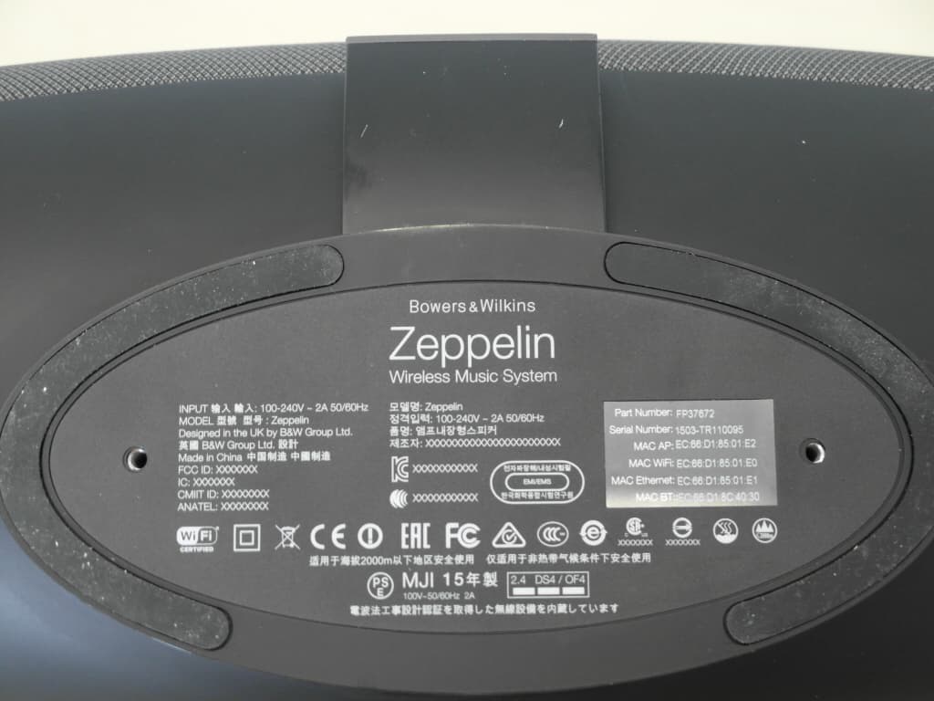
Click to zoom
Application Details
- Equipment Class
- DTS - Digital Transmission System
- Date of Grant
- Jul 30, 2015
- Application Purpose
- Original Equipment
- Date of Application
- Jul 30, 2015
- Equipment Note
- Wireless music system
- Frequency Range
- 2412.00000000 - 2462.00000000
- Company
- B&W Group Ltd.
- Country
- United Kingdom
Documents & Files
Document Text
Text extracted from the exhibit documents filed with the FCC. Open a document above to read the original.
Users Manual
DRAFT Zeppelin Wireless 2 ENGLISH www.bowers-wilkins.com Welcome to Bowers & Wilkins and Zeppelin Wireless Thank you for choosing Bowers & Wilkins. When John Bowers first established our company he did so in the belief that imaginative design, innovative engineering and advanced technology were keys that could unlock the enjoyment of audio in the home. His belief is one that we continue to share and it inspires every product we design. Zeppelin Wireless can be used to: • Stream audio via AirPlay using either a cable or wireless network connection. • Play audio streams via either a cable or wireless network connection from Spotify ® using the Spotify Connect feature built into some Spotify apps. Note: A Spotify Premium account is required for Spotify Connect. Spotify functionality may be limited by region. • Play music wirelessly from an iOS, Android or popular Bluetooth ® devices. • Play music via an Aux input from a conventional analogue source using a 3.5mm Jack connection cable. To control and operate your Zeppelin Wireless you can use either its buttons or the music streaming apps on your iOS, Android or Windows Mobile device. The Bowers & Wilkins Control app can also be used for Zeppelin Wireless network set up, stream playback and volume control, Bluetooth pair management and product registration. This manual will tell you everything you need to know to get the most from your Zeppelin Wireless. It begins by describing the contents of the Zeppelin Wireless carton. 3 ENGLISH 1. Zeppelin Wireless Carton Contents i. Zeppelin Wireless ii. Power cable iii. Literature pack Environmental Information This product complies with international directives, including but not limited to the Restriction of Hazardous Substances (RoHS) in electrical and electronic equipment, the Registration, Evaluation, Authorisation and restriction of Chemicals (REACH) and the disposal of Waste Electrical and Electronic Equipment (WEEE). Consult your local waste disposal authority for guidance on how properly to recycle or dispose of this product. 2. Getting to know Zeppelin Wireless Zeppelin Wireless is designed for very high performance and convenient music streaming. For best acoustic performance your Zeppelin Wireless should be positioned on a shelf or table, or wall mounted using the accessory wall bracket available from your local retailer or directly from Bowers & Wilkins. On the top of the Zeppelin Wireless body are volume and playback controls. These can be used to raise or lower the volume, to play or pause a music stream, and to select the next or previous track. A status indicator is located within the Bowers & WIlkins logo on the front of the product. The status indicator changes colour and illumination pattern to indicate different operational states. Status indicator colours and illumination patterns are listed in Section 6 of this manual. The Zeppelin Wireless also provides some audible feedback when control or network events occur. On each side of the Bowers & Wilkins logo at the front of the Zeppelin Wireless body are a Bluetooth touch button and indicator and an Aux input touch button and indicator. The Bluetooth button is on the right and the Aux button is on the left. Bluetooth pairing and use of the Aux input are described in Sections 3.2 and 3.3 respectively. Connection sockets on the rear of Zeppelin Wireless comprise a mains power input, a 3.5mm analogue Aux input, a network socket and a micro-USB interface used for service only. A standby button and a pin-hole reset button are also located on the rear of Zeppelin Wireless. Diagram 1 illustrates Zeppelin Wireless, its buttons, indicators and connection sockets. Zeppelin Wireless is designed to be simple and convenient in operation and will automatically play the most recent audio stream or input signal it receives. There is no to need manually select sources or the Aux input. Diagram 1 Buttons and connection sockets 3. Switching on and setting up When your Zeppelin Wireless is first connected to a mains power supply it will enter standby mode. To wake Zeppelin Wireless from standby press power button. The top panel indicator will initially pulse red and then pulse green to indicate that Zeppelin Wireless is ready for network connection mode. Note: If your Zeppelin Wireless has been previously used, or you now wish to use it with a different network and Bluetooth devices it is good practice to return it to its default settings using the reset button. See Section 7 for more on using the reset button. Bluetooth buttonSource select Indicator Play/PauseVolume up Volume down Power on/Power offEthernetPowerAuxiliaryReboot 4 ENGLISH 3.1 Network Connection Your Zeppelin Wireless can only stream audio when connected to the same network as the source device. Note: Your Zeppelin Wireless can play Bluetooth streams and Aux input audio without a network connection. If you wish to connect your Zeppelin Wireless to your home Wi Fi Network iPhone and iPad owners should download ‘Bowers & Wilkins Control’ app from www.bowers-wilkins.co.uk/control or by searching the App Store SM for ‘Bowers & Wilkins’. Mac and PC owners should download the desktop version of ‘Bowers & Wilkins Control’ app from www. bowers-wilkins.co.uk/control. Connect Zeppelin Wireless to your home network by following the instructions within the app. Upon first use Zeppelin Wireless will enter network configuration mode, with the indicator pulsing green. Bluetooth and auxiliary inputs are unavailable until network connection has been addressed. If your Zeppelin Wireless is to use a wired network connection, it can simply be connected using a network cable to the network router. To do this follow the steps below: • Disconnect your Zeppelin Wireless from mains power. • Connect your Zeppelin Wireless to your network router using a high quality, shielded network cable. • Reconnect your Zeppelin Wireless to mains power and switch it on using the standby button. • After a short delay, during wh…
Text truncated - open the document above for the full version.
Users Manual
Italiano Informazioni importanti sulla sicurezza Spiegazione dei simboli grafici ATTENZIONE: Per evitare il rischio di scossa elettrica, non smontate l’apparecchio. Non contiene parti riparabili dall’utente. Fate riferimento a personale qualificato per l’assistenza. Il fulmine inserito in un triangolo vi avverte della presenza di materiale non isolato, sotto tensione, ad elevato voltaggio all’interno del prodotto che può costituire per le persone pericolo di folgorazione. Il punto esclamativo entro un triangolo equilatero vi avverte della presenza di istruzioni d’uso e manutenzione importanti nel manuale o nella documentazione che accompagna il prodotto. 1 Leggere queste istruzioni. 2 Conservare le istruzioni. 3 Seguite tutte le avvertenze riportate in questo manuale. 4 Seguite le istruzioni sull’utilizzo del prodotto. 5 Non utilizzate questo prodotto vicino all’acqua. 6 Pulite il prodotto solo con un panno asciutto. 7 Non ostruite le aperture per la ventilazione. Installate il prodotto secondo le indicazioni del costruttore. 8 Non posizionate l’apparecchio vicino a fonti di calore come termosifoni, stufe o altri prodotti (inclusi gli amplificatori) che producano calore. 9 Non cercate di eliminare la messa a terra o la polarizzazione della spina. Se la spina del cavo ha difficoltà ad entrare nella presa di alimentazione, consultate un elettricista per una eventuale sostituzione della presa. Non utilizzate prolunghe. 10 Non fate passare i cavi di alimentazione dove potrebbero essere calpestati o danneggiati, fate particolare attenzione al posizionamento del cavo di alimentazione in corrispondenza della presa e del punto di uscita dell’apparecchio. 11 Usate solo accessori raccomandati dal costruttore. 12 Utilizzate solo stand, scaffali o supporti indicati dal produttore o veduti assieme al prodotto stesso. Se posizionate il prodotto su un carrello mobile fate attenzione quando lo spostate poiché potrebbe cadere. 13 Scollegate il cavo di alimentazione dalla presa durante i temporali o quando l’apparecchiatura rimane inutilizzata per un periodo piuttosto lungo. 14 In caso di necessità di assistenza tecnica fate riferimento solo a personale qualificato, nel caso in cui l’apparecchio sia stato danneggiato o se il cavo di alimentazione o la spina siano stati danneggiati, se del liquido o degli oggetti siano penetrati nell’apparecchio, se l’apparecchio è stato esposto a pioggia o all’acqua, se il prodotto non funziona normalmente o se è caduto. 15 ATTENZIONE: Per ridurre il rischio di incendio e di scossa elettrica non esponete l’apparecchio all’umidità o all’acqua. Non posizionate contenitori di liquidi, come ad esempio vasi contenenti acqua, su di esso. 16 Nei casi in cui il dispositivo non sia dotato di un interruttore per scollegarlo dall’alimentazione AC, per disconnetterlo completamente dalla rete AC, disattivate la presa di rete se comandata, o scollegate il cavo di alimentazione dalla presa. La presa di rete del cavo di alimentazione dovrebbe essere sempre accessibile. Nota: L’interruttore di standby non disconnette l’apparato dall’alimentazione. 17 Sostituite i fusibili solo con altri dello stesso tipo o equivalenti come indicato sul dispositivo. 18 Gli apparecchi costruiti in Classe I devono essere connessi ad una presa di alimentazione dotata di messa a terra. Gli apparecchi contrassegnati dal simbolo doppio isolamento non necessitano della messa a terra. 19 Alcuni prodotti vengono venduti in più paesi e vengono forniti con più versioni del cavo di alimentazione. Utilizzate solo il tipo idoneo alla vostra rete elettrica. 20 Dovendo sollevare un prodotto, prenderlo sempre alla base. 21 Adottare sempre una corretta postura durante il sollevamento. 22 Prima di spostare il prodotto, toglietevi anelli, braccialetti o similari che potrebbero danneggiare le superfici. 23 Gli altoparlanti dei diffusori generano un campo magnetico. Non posizionate oggetti che potrebbero venirne danneggiati (ad es. nastri audio e video, carte di credito o similari) entro una distanza di 0.5m dall’unità. Il campo magnetico potrebbe causare distorsioni sullo schermo di un TV o monitor per PC di tipo CRT. Schermi al Plasma, LED o OLED non sono interessati da questi fenomeni. 24 Assicurarsi che il piano dove si intende posizionare il prodotto sia adatto a sostenerne il peso. 25 Eventuali vibrazioni prodotte possono far muovere gli oggetti circostanti. Assicurarsi che questi oggetti non siano a rischio di caduta o possano danneggiarsi. 26 Questo prodotto è progettato per funzionare ad una normale temperatura ambiente non superiore a 45° centigradi. 27 Assicurarsi che la presa elettrica a muro alla quale è collegato l’appareccio sia facilmente accessibile. 28 L’alimentatore di questo prodotto deve essere utilizzato solo al chiuso. NON è progettato per l’utilizzo all’aperto, su imbarcazioni o veicoli ricreazionali. 29 Smaltire questo prodotto in conformità alla normativa vigente. Questo prodotto non deve essere gettato assieme ai normali rifiuti domestici. 30 Non consentire ai bambini di utilizzare questo prodotto senza la supervisione di un adulto. Garanzia I prodotti Bowers & Wilkins sono progettati e costruiti secondo i più elevati standard qualitativi. Comunque, se dovesse insorgere qualche problema, B&W Group Ltd. ed i suoi distributori garantiscono interventi di riparazione e parti di ricambio in garanzia (potrebbero esservi alcune eccezioni) in qualsiasi paese in cui è presente un distributore ufficiale Bowers & Wilkins. Questa garanzia integra qualsiasi normativa nazionale o regionale di rivenditori o distributori e non ha alcun effetto sui vostri diritti come cliente. Alcune restrizioni legali regionali al di fuori del ragionevole controllo di B&W Group Ltd. potrebbero ridurre l’effetto o il periodo dei termini sotto indicati. In particolare: • Termini speciali di garanzia applicati nella Federazione Russa. • Specifiche regole di importazione applicate in Brasile. Per ulteriori dettagli Vi preghiamo di contat…
Text truncated - open the document above for the full version.
External Photos
Test report no.: 1-9611/15-01-01_AnnexA Annex A This test report annex is electronically signed and valid without handwriting signature. For verification of the electronic signatures, the public keys can be requested at the testing laboratory. Test report annex authorised: Mihail Dorongovskij Testing Manager Radio Communications & EMC Page 1 of 4 Test report no.: 1-9611/15-01-01_AnnexA External photos of the EUT Photo 1: EUT front view Photo 2: EUT side view Page 2 of 4 Test report no.: 1-9611/15-01-01_AnnexA Photo 3: EUT rear view Page 3 of 4 Test report no.: 1-9611/15-01-01_AnnexA Document history Version Applied changes Date of release Initial release 2015-06-15 Page 4 of 4
ID Label/Location Info
14012015 Zeppelin Wireless (ZD-2B) Global Rating Label 3 Template updated to incorporate cutouts. COPYRIGHT 2015 KH SAP DOCUMENT NUMBER 3M7818 PART No. SS17434 Black Print 4 UL logo added, CSA and FCC removed. 5 1st MP version for NA-EC ARTWORK PRINT THIS VERSION DO NOT PRINT THIS VERSION INPUT 输入 輸入: 100-240V ~ 2A 50/60Hz MODEL 型號 型号 : Zeppelin Wireless Designed in the UK by B&W Group Ltd. 英國 B&W Group Ltd. 設計 Made in China 中国制造 中國制造 产品名称:无线音乐系统 產品名稱:無線音樂系統 Zeppelin Wireless FCC ID: 2ACIX-ZW IC: 11946B-ZW
Internal Photos
Test report no.: 1-9611/15-01-01_AnnexB Page 1 of 10 Annex B This test report annex is electronically signed and valid without handwriting signature. For verification of the electronic signatures, the public keys can be requested at the testing laboratory. Test report annex authorised: Mihail Dorongovskij Testing Manager Radio Communications & EMC Test report no.: 1-9611/15-01-01_AnnexB Page 2 of 10 Internal photos of the EUT Photo 1: back cover removed Photo 2: PCB 1 Test report no.: 1-9611/15-01-01_AnnexB Page 3 of 10 Photo 3: PCB 1 and 2 Photo 4: PCB 2 Test report no.: 1-9611/15-01-01_AnnexB Page 4 of 10 Photo 5: Transmit antenna Photo 6: Transmit antenna Test report no.: 1-9611/15-01-01_AnnexB Page 5 of 10 Photo 7: PCB 1 lifted Photo 8: PCB 3 Test report no.: 1-9611/15-01-01_AnnexB Page 6 of 10 Photo 9: detailed PCB 3 Photo 10: Antenna 2 Test report no.: 1-9611/15-01-01_AnnexB Page 7 of 10 Photo 11: detailed antenna 2 Photo 12: PCB 3 & 4 backside Test report no.: 1-9611/15-01-01_AnnexB Page 8 of 10 Photo 13: PCB 3 backside Photo 14: PCB 4 front side with aluminium shielding Test report no.: 1-9611/15-01-01_AnnexB Page 9 of 10 Photo 15: PCB 4 front side without aluminium shielding Test report no.: 1-9611/15-01-01_AnnexB Page 10 of 10 Document history Version Applied changes Date of release A Photo 1 removed. 2015-07-29
RF Exposure Info
FCC ID: 2ACIX-ZW Model: Zeppelin Wireless Prediction of MPE limit at given distance Equation from page 18 of OET Bulletin 65, Edition 97-01 S = PG / 4π R 2 where: S = Power density P = Power input to the antenna G = Antenna gain R = Distance to the center of radiation of the antenna The table below is excerpted from Table 1B of 47 CFR 1.1310 titled “Limits for Maximum Permissible Exposure (MPE), Limits for General Population/Uncontrolled Exposure” Frequency Range (MHz) Power Density (mW/cm 2 ) Averaging Time (minutes) 300 -1500 f/1500 30 1500 - 100000 1.0 30 where f = Frequency (MHz) Prediction: WLAN Bluetooth P Max power input to the antenna: 212.32 mW * 1 2.10 mW * 1 R Distance: 20 cm 20 cm S MPE limit for uncontrolled exposure: 1 mW/cm 2 1 mW/cm 2 G Antenna gain: 0.94 1.45 Calculated Power density: 0.0397 mW/cm 2 0.0006 mW/cm 2 Result in % of MPE limit: 0.397 % 0.006 % Result for co-location in % for both technologies 0.403 % *1 declared power shown in operational description This prediction demonstrates the following: The power density levels at a distance of 20 cm are below the maximum levels allowed by regulations. Christoph Schneider Cetecom ICT Services GmbH 2015-07-27
Test Report
Document 75917143 Report 05 Issue 3 July 2012 Report On FCC and Industry Canada Testing of the Frontier Silicon Ltd Venice 6.5 In accordance with FCC CFR 47 Part 15C, Industry Canada RSS-210 and Industry Canada RSS-GEN COMMERCIAL-IN-CONFIDENCE FCC ID: YYX-HA-FS2026-F5 IC ID: NOT YET SUPPLIED TÜV SÜD Product Service Ltd, Octagon House, Concorde Way, Segensworth North, Fareham, Hampshire, United Kingdom, PO15 5RL Tel: +44 (0) 1489 558100. Website: www.tuvps.co.uk COMMERCIAL-IN-CONFIDENCE Document 75917143 Report 05 Issue 3 Page 1 of 207 COMMERCIAL-IN-CONFIDENCE REPORT ON FCC and Industry Canada Testing of the Frontier Silicon Ltd Venice 6.5 In accordance with FCC CFR 47 Part 15C, Industry Canada RSS-210 and Industry Canada RSS-GEN Document 75917143 Report 05 Issue 3 July 2012 PREPARED FOR Frontier Silicon Ltd Dales Manor Business Park Babraham Road Sawston Cambridge CB22 3LJ United Kingdom PREPARED BY Natalie Bennett Senior Administrator (Technical) APPROVED BY Mark Jenkins Authorised Signatory DATED 06 July 2012 This report has been up-issued to Issue 3 to correct the application form. ENGINEERING STATEMENT The measurements shown in this report were made in accordance with the procedures described on test pages. All reported testing was carried out on a sample equipment to demonstrate limited compliance with FCC CFR 47 Part 15C, Industry Canada RSS-210 and Industry Canada RSS-GEN. The sample tested was found to comply with the requirements defined in the applied rules. Test Engineer(s); G Lawler B Airs Document 75917143 Report 05 Issue 3 Page 2 of 207 COMMERCIAL-IN-CONFIDENCE COMMERCIAL-IN-CONFIDENCE CONTENTS Section Page No 1 REPORT SUMMARY ................................................................................................................... 3 1.1 Introduction ................................................................................................................................... 4 1.2 Brief Summary of Results ............................................................................................................. 5 1.3 Application Form ........................................................................................................................... 7 1.4 Product Information .................................................................................................................... 12 1.5 Test Conditions ........................................................................................................................... 12 1.6 Deviations from the Standard ..................................................................................................... 12 1.7 Modification Record .................................................................................................................... 12 2 TEST DETAILS .......................................................................................................................... 13 2.1 AC Line Conducted Emissions ................................................................................................... 14 2.2 Maximum Peak Conducted Output Power ................................................................................. 17 2.3 EIRP Peak Power ....................................................................................................................... 22 2.4 Spurious and Band Edge Emissions .......................................................................................... 47 2.5 Power Spectral Density ............................................................................................................ 107 2.6 6dB Bandwidth .......................................................................................................................... 154 3 TEST EQUIPMENT USED ....................................................................................................... 201 3.1 Test Equipment Used ............................................................................................................... 202 3.2 Measurement Uncertainty ........................................................................................................ 205 4 ACCREDITATION, DISCLAIMERS AND COPYRIGHT .......................................................... 206 4.1 Accreditation, Disclaimers and Copyright ................................................................................. 207 Document 75917143 Report 05 Issue 3 Page 3 of 207 COMMERCIAL-IN-CONFIDENCE COMMERCIAL-IN-CONFIDENCE SECTION 1 REPORT SUMMARY FCC and Industry Canada Testing of the Frontier Silicon Ltd Venice 6.5 In accordance with FCC CFR 47 Part 15C, Industry Canada RSS-210 and Industry Canada RSS-GEN Document 75917143 Report 05 Issue 3 Page 4 of 207 COMMERCIAL-IN-CONFIDENCE COMMERCIAL-IN-CONFIDENCE 1.1 INTRODUCTION The information contained in this report is intended to show verification of the FCC and Industry Canada Testing of the Frontier Silicon Ltd Venice 6.5 to the requirements of FCC CFR 47 Part 15C, Industry Canada RSS-210 and Industry Canada RSS-GEN. Objective To perform FCC and Industry Canada Testing to determine the Equipment Under Test's (EUT’s) compliance with the Test Specification, for the series of tests carried out. Manufacturer Frontier Silicon Ltd Model Number(s) Venice 6.5 Serial Number(s) 1) Conducted PIFA Sample, S/N: RAD103037 on Test Jig S/N: RAD103234 2) External Antenna Radiated Sample, S/N: RAD103021 on Test Jig S/N: RAD103235 3) Radiated PIFA Sample, S/N: RAD103045 on Test Jig, S/N: RAD103235 Number of Samples Tested 3 Test Specification/Issue/Date FCC CFR 47 Part 15C (2011) Industry Canada RSS-210 (2010) Industry Canada RSS-GEN (2010) Incoming Release Date Application Form 29 May 2012 Disposal Reference Number Date Held Pending Disposal Not Applicable Not Applicable Order Number Date FS021247 17 February 2012 Start of Test 29 February 2012 Finish of Test 9 April 2012 Name of Engineer(s) G Lawler B Airs Related Document(s) ANSI C63.10: 2009 Document 759171…
Text truncated - open the document above for the full version.
Test Report
TEST REPORT Test report no.: 1-9611/15-01-09-A Testing laboratory Applicant CETECOM ICT Services GmbH Untertuerkheimer Strasse 6 – 10 66117 Saarbruecken / Germany Phone: + 49 681 5 98 - 0 Fax: + 49 681 5 98 - 9075 Internet: http://www.cetecom.com e-mail: [email protected] Accredited Testing Laboratory: The testing laboratory (area of testing) is accredited according to DIN EN ISO/IEC 17025 (2005) by the Deutsche Akkreditierungsstelle GmbH (DAkkS) The accreditation is valid for the scope of testing procedures as stated in the accreditation certificate with the registration number: D-PL-12076-01-00 Bowers & Wilkins Dale Rd, Worthing, West Sussex BN11 2BH / UNITED KINGDOM Phone: -/- Fax: -/- Contact: -/- -/- e-mail: -/- Phone: -/- Manufacturer Bowers & Wilkins Dale Rd, Worthing, West Sussex BN11 2BH / UNITED KINGDOM Test standard/s 47 CFR Part 15 Title 47 of the Code of Federal Regulations; Chapter I; Part 15 - Radio frequency devices RSS - 247 Issue 1 Digital Transmission Systems (DTSs), Frequency Hopping Systems (FHSs) and Licence - Exempt Local Area Network (LE-LAN) Devices For further applied test standards please refer to section 3 of this test report. Test Item Kind of test item: Wireless music system Model name: Zeppelin Wireless FCC ID: 2ACIX-ZW IC: 11946B-ZW Frequency: DTS band 2400 MHz to 2483.5 MHz Technology tested: WLAN (DSSS/b-mode; OFDM/g-; n/HT20-mode) Antenna: Integrated antenna Power supply: 110 V AC by internal power supply unit Temperature range: +5°C to +35°C This test report is electronically signed and valid without handwriting signature. For verification of the electronic signatures, the public keys can be requested at the testing laboratory. Test report authorised: Test performed: Marco Bertolino Christoph Schneider Lab Manager Testing Manager Radio Communications & EMC Radio Communications & EMC Test report no.: 1-9611/15-01-09-A Page 2 of 56 1 Table of contents 1 Table of contents ............................................................................................................................................ 2 2 General information ....................................................................................................................................... 3 2.1 Notes and disclaimer .......................................................................................................................... 3 2.2 Application details ............................................................................................................................... 3 3 Test standard/s ............................................................................................................................................... 3 3.1 Measurement guidance ....................................................................................................................... 3 4 Test environment ............................................................................................................................................ 4 5 Test item .......................................................................................................................................................... 4 5.1 Additional information ........................................................................................................................ 4 6 Test laboratories sub-contracted ................................................................................................................. 4 7 Description of the test setup ......................................................................................................................... 5 7.1 Shielded semi anechoic chamber ...................................................................................................... 6 7.2 Shielded fully anechoic chamber ...................................................................................................... 7 7.3 Radiated measurements > 12.75 GHz................................................................................................ 8 7.4 AC conducted ...................................................................................................................................... 9 8 Summary of measurement results ............................................................................................................. 10 9 Additional comments ................................................................................................................................... 11 10 Measurement results ................................................................................................................................ 12 10.1 System gain .................................................................................................................................... 12 10.2 Identify worst case data rate ......................................................................................................... 13 10.3 Occupied bandwidth – 99% emission bandwidth....................................................................... 14 10.4 Band edge compliance radiated ................................................................................................... 21 10.5 Spurious emissions radiated below 30 MHz ............................................................................... 25 10.6 Spurious emissions radiated 30 MHz to 1 GHz ........................................................................... 30 10.7 Spurious emissions radiated above 1 GHz ................................................................................. 38 10.8 Spurious emissions conducted below 30 MHz (AC conducted) ............................................... 52 11 Observations ............................................................................................................................................. 55 Annex A Document history .....................................................................................…
Text truncated - open the document above for the full version.
Test Setup Photos
Test report no.: 1-9611/15-01-01_AnnexD Annex D This test report annex is electronically signed and valid without handwriting signature. For verification of the electronic signatures, the public keys can be requested at the testing laboratory. Test report annex authorised: Mihail Dorongovskij Testing Manager Radio Communications & EMC Page 1 of 6 Test report no.: 1-9611/15-01-01_AnnexD EUT Test setup photos Photo 1: EUT at the anechoic chamber Photo 2: EUT at the anechoic chamber Page 2 of 6 Test report no.: 1-9611/15-01-01_AnnexD Photo 3: EUT at the anechoic chamber Photo 4: EUT at the anechoic chamber Page 3 of 6 Test report no.: 1-9611/15-01-01_AnnexD Photo 5: EUT at the anechoic chamber Photo 6: EUT at the semi anechoic chamber Page 4 of 6 Test report no.: 1-9611/15-01-01_AnnexD Photo 7: AC conducted emission measurement Page 5 of 6 Test report no.: 1-9611/15-01-01_AnnexD Document history Version Applied changes Date of release Initial release 2015-06-15 Page 6 of 6
Contact Information
Applicant
Pat Sullivan(Director of HW Quality Assurance)
Test Firm
cetecom advanced GmbHGerald Schmidt
Technical Specifications
| # | Rule Parts | Frequency Range | Power Output |
|---|---|---|---|
| 1 | 15C | 2.41 GHz - 2.46 GHz | 220.00 mW |
Other Applications from B&W Group Ltd.
2ACIX-PI8EB
Jul 03, 2024In-ear True Wireless Earbuds
Equipment Class
DTS - Digital Transmission System2ACIX-PI6EB
Jun 23, 2024In-ear True Wireless Earbuds
Equipment Class
DTS - Digital Transmission System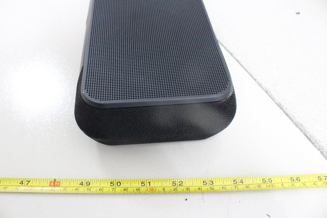
2ACIX-PAN
May 30, 2021Wireless Active Soundbar
Equipment Class
DSS - Part 15 Spread Spectrum Transmitter
2ACIX-PI7L
Jan 07, 2021In-ear True Wireless Headphone
Equipment Class
DTS - Digital Transmission System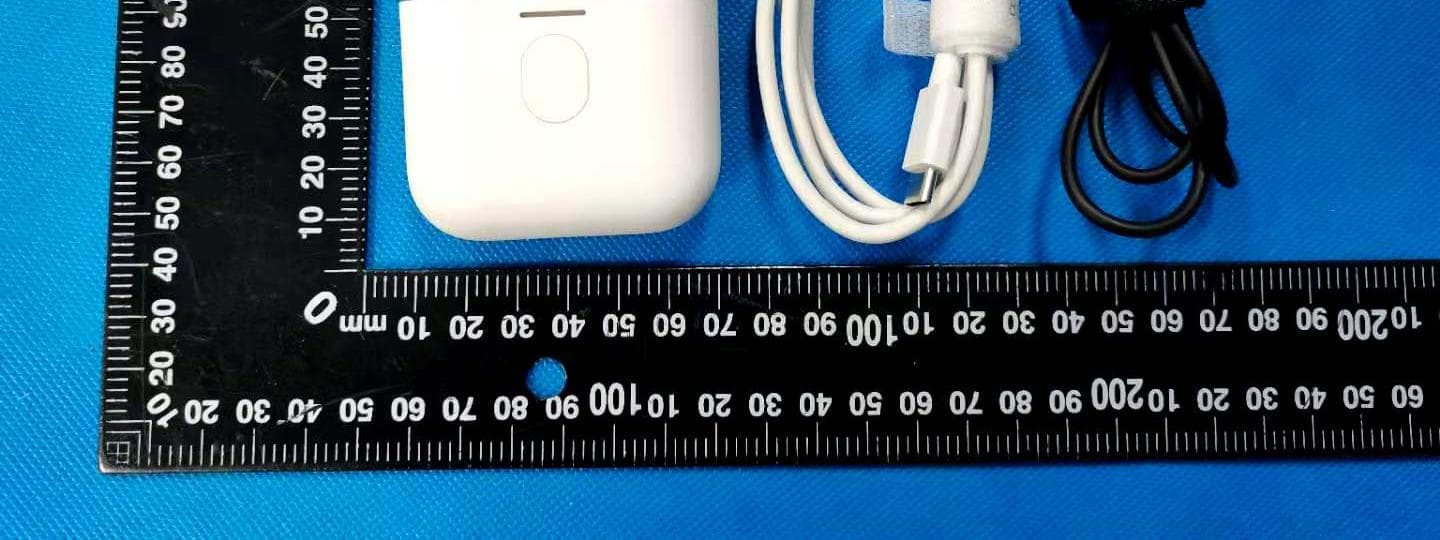
2ACIX-PI7C
Jan 06, 2021In-ear True Wireless Headphone(charging case of TWS headphones)
Equipment Class
DSS - Part 15 Spread Spectrum Transmitter