2ACJF-ME4624-ONTRGWWireless Optical Network Termination (ONT)
Altice Labs, S.A.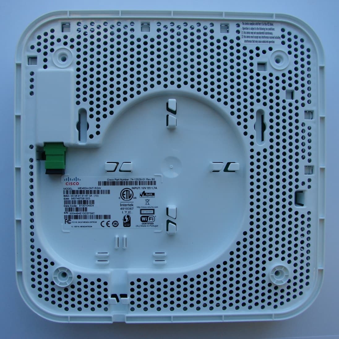
Click to zoom
Application Details
- Equipment Class
- DTS - Digital Transmission System
- Date of Grant
- Mar 17, 2015
- Application Purpose
- Original Equipment
- Date of Application
- Mar 16, 2015
- Equipment Note
- Wireless Optical Network Termination (ONT)
- Frequency Range
- 2412.00000000 - 2462.00000000
- Company
- Altice Labs, S.A.
- Country
- Portugal
Documents & Files
Document Text
Text extracted from the exhibit documents filed with the FCC. Open a document above to read the original.
Users Manual
ME4600 Optical Network Termination Residential Gateway User Manual Version 3.2-3 Last Updated March 2015 Cisco Systems, Inc. www.cisco.com Cisco has more than 200 offices worldwide. Addresses, phone numbers, and fax numbers are listed on the Cisco website at www.cisco.com/go/offices. THE SPECIFICATIONS AND INFORMATION REGARDING THE PRODUCTS IN THIS MANUAL ARE SUBJECT TO CHANGE WITHOUT NOTICE. ALL STATEMENTS, INFORMATION, AND RECOMMENDATIONS IN THIS MANUAL ARE BELIEVED TO BE ACCURATE BUT ARE PRESENTED WITHOUT WARRANTY OF ANY KIND, EXPRESS OR IMPLIED. USERS MUST TAKE FULL RESPONSIBILITY FOR THEIR APPLICATION OF ANY PRODUCTS. THE SOFTWARE LICENSE AND LIMITED WARRANTY FOR THE ACCOMPANYING PRODUCT ARE SET FORTH IN THE INFORMATION PACKET THAT SHIPPED WITH THE PRODUCT AND ARE INCORPORATED HEREIN BY THIS REFERENCE. IF YOU ARE UNABLE TO LOCATE THE SOFTWARE LICENSE OR LIMITED WARRANTY, CONTACT YOUR CISCO REPRESENTATIVE FOR A COPY. The Cisco implementation of TCP header compression is an adaptation of a program developed by the University of California, Berkeley (UCB) as part of UCB’s public domain version of the UNIX operating system. All rights reserved. Copyright © 1981, Regents of the University of California. NOTWITHSTANDING ANY OTHER WARRANTY HEREIN, ALL DOCUMENT FILES AND SOFTWARE OF THESE SUPPLIERS ARE PROVIDED “AS IS” WITH ALL FAULTS. CISCO AND THE ABOVE-NAMED SUPPLIERS DISCLAIM ALL WARRANTIES, EXPRESSED OR IMPLIED, INCLUDING, WITHOUT LIMITATION, THOSE OF MERCHANTABILITY, FITNESS FOR A PARTICULAR PURPOSE AND NONINFRINGEMENT OR ARISING FROM A COURSE OF DEALING, USAGE, OR TRADE PRACTICE. IN NO EVENT SHALL CISCO OR ITS SUPPLIERS BE LIABLE FOR ANY INDIRECT, SPECIAL, CONSEQUENTIAL, OR INCIDENTAL DAMAGES, INCLUDING, WITHOUT LIMITATION, LOST PROFITS OR LOSS OR DAMAGE TO DATA ARISING OUT OF THE USE OR INABILITY TO USE THIS MANUAL, EVEN IF CISCO OR ITS SUPPLIERS HAVE BEEN ADVISED OF THE POSSIBILITY OF SUCH DAMAGES. Cisco and the Cisco Logo are trademarks of Cisco Systems, Inc. and/or its affiliates in the U.S. and other countries. A listing of Cisco's trademarks can be found at www.cisco.com/go/trademarks. Third party trademarks mentioned are the property of their respective owners. The use of the word partner does not imply a partnership relationship between Cisco and any other company. Any Internet Protocol (IP) addresses and phone numbers used in this document are not intended to be actual addresses and phone numbers. Any examples, command display output, network topology diagrams, and other figures included in the document are shown for illustrative purposes only. Any use of actual IP addresses or phone numbers in illustrative content is unintentional and coincidental. © 2015 Cisco Systems, Inc. All rights reserved. FCC/IC NOTICE This device complies with FCC part 15 FCC Rules. Operation is subject to the following two conditions: 1. This device may not cause harmful interference and 2. This device must accept any interference, including interference that may cause undesired operation of the device Caution: Changes or modifications not expressly approved by the party responsible for compliance could void the user’s authority to operate the equipment. Note: This equipment has been tested and found to comply with the limits for a Class B digital device, pursuant to part 15 of the FCC Rules. These limits are designed to provide reasonable protection against harmful interference in a residential installation. This equipment generates, uses and can radiate radio frequency energy and, if not installed and used in accordance with the instructions, may cause harmful interference to radio communications. However, there is no guarantee that interference will not occur in a particular installation. If this equipment does cause harmful interference to radio or television reception, which can be determined by turning the equipment off and on, the user is encouraged to try to correct the interference by one or more of the following measures: Reorient or relocate the receiving antenna. Increase the separation between the equipment and receiver. Connect the equipment into an outlet on a circuit different from that to which the receiver is connected. Consult the dealer or an experienced radio/TV technician for help. This device meets the FCC and IC requirements for RF exposure in public or uncontrolled environments. Cet appareil est conforme aux conditions de la FCC et IC en matière de RF dans des environnements publics ou incontrôlée. This device complies with Industry Canada license exempt RSS standard(s). Operation is subject to the following two conditions: 1. this device may not cause interference, and 2. this device must accept any interference, including interference that may cause undesired operation of the device. Cet appareil est conforme avec Industrie Canada RSS standard exempts de licence (s). Son utilisation est soumise à Les deux conditions suivantes: 1. cet appareil ne peut pas provoquer d’interférences et 2. cet appareil doit accepter Toute interférence, y compris les interférences qui peuvent causer un mauvais fonctionnement du dispositive. CAN ICES-3 (B)/NMB-3(B) ME4600 Optical Network Termination Residential Gateway User Manual ▄ 3 CONTENTS Chapter 1 SUMMARY ........................................................................................................................ 16 Chapter 2 TECHNICAL DESCRIPTION ...................................................................................... 17 ONT-RGW MAIN FUNCTIONALITIES ................................................................................................... 17 APPLICATION SCENARIO ................................................................................................................ 17 INTEROPERABILITY ......................................................................................................................... 18 INTERFACES .......................................................................…
Text truncated - open the document above for the full version.
Block Diagram
6 Technical Description 2.1.2 Block Diagram The ONT –RGW circuit block diagram is presented in the figure bellow showing all oscillators in the device and its frequencies, Figure 2.1-1. Intentional radiators in the circuit and radio signal path between circuit blocks are also shown. 20MHz WIFI 2x2 2.4GHz DDR3 Flash POWER DC/DC 12 V LED Driver PCIe PCIe DDR3 FMI 390KHz 700KHz R J11 VOICE SLIC R J11 SoC CTRL 2xFXS SC- O GPON SPI R J45 C DR AP E MAC R J45 25 MHz 100 MHz 125 MHz 240 MHz 533 MHz ETH MAC R J45 R J45 600 MHz 800 MHz Figure 2.1-1: ONT-RGW circuit block diagram
External Photos
Photos: ME4624-ONT-RGW FCC ID: 2ACJF-ME4624-ONTRGW IC: 12071A-ME4624NTRGW ME4624-ONT-RGW: External Photos (1/6) ME4624-ONT-RGW: External Photos (2/6) ME4624-ONT-RGW: External Photos (3/6) ME4624-ONT-RGW: External Photos (4/6) ME4624-ONT-RGW: External Photos (5/6) ME4624-ONT-RGW: External Photos (6/6)
ID Label/Location Info
Photos: ME4624-ONT-RGW FCC ID: 2ACJF-ME4624-ONTRGW IC: 12071A-ME4624NTRGW ME4624-ONT-RGW: Photos of Label and Label location (1/3) ME4624-ONT-RGW: Photos of Label and Label location (2/3) ME4624-ONT-RGW: Photos of Label and Label location (3/3)
Internal Photos
ME4624-ONT-RGW: Internal photos (1/2) ME4624-ONT-RGW: Internal photos (2/2)
RF Exposure Info
731 Enterprise Drive Lexington, KY 40510 Telephone: 859- 226- 1000 Facsimile: 859- 226- 1040 www.intertek-etlsemko.com MPE Calculation § 1.1310: The criteria listed in table 1 shall be used to evaluate the environmental impact of human exposure to radiofrequency (RF) radiation as specified in §1.1307(b), except in the case of portable devices which shall be evaluated according to the provisions of §2.1093 of this chapter. Part 1.1310 Limits for Maximum Permissible Exposure (MPE) 1.1 Test Procedure An MPE evaluation for was performed in order to show that the device was compliant with §2.1091. The maximum power density was calculated for each transmitter at a separation distance of 20cm. For each transmitter the maximum RF exposure at a 20 cm distance using the formula: 10/)( 10 dBmowerConductedP mW PowerConducted= 2 )20(4 . cm mW GainAntPowerConducted tyPowerDensi × × = π 731 Enterprise Drive Lexington, KY 40510 Telephone: 859- 226- 1000 Facsimile: 859- 226- 1040 www.intertek-etlsemko.com 1.2 Results: • Maximum Conducted Output Power = 311.9mW • Maximum Antenna Gain = 1.6dBi Power Density = (311.9mW x 1.45) / 5025.6 Power Density = 0.09 mW/cm 2 Limit at 2.4GHz = 1mW/cm 2 The calculated maximum power density at 20cm distance is less that the limit for general population / uncontrolled exposure.
Schematics
ME4624-ONT-RGW and ME4624-ONT-RGW-RF - Radio Portion Schematic FCC ID: 2ACJF-ME4624-ONTRGW and FCC ID: 2ACJF-ME4624-ONTWRF
Test Report
This report is for the exclusive use of Intertek's Client and is provided pursuant to the agreement between Intertek and its Client. Intertek's responsibility and liability are limited to the terms and conditions of the agreement. Intertek assumes no liability to any party, other than to the Client in accordance with the agreement, for any loss, expense or damage occasioned by the use of this report. Only the Client is authorized to permit copying or distribution of this report and then only in its entirety. Any use of the Intertek name or one of its marks for the sale or advertisement of the tested material, product or service must first be approved in writing by Intertek. The observations and test results in this report are relevant only to the sample tested. This report by itself does not imply that the material, product, or service is or has ever been under an Intertek certification program. EMC Report for Portugal Telecom, Inovacao S.A. on the Cisco ME4624-ONT-RGW / PTIN GR2402G Page 1 of 42 731 Enterprise Drive Lexington, KY 40510 Telephone: 859-226-1000 Facsimile: 859-226-1040 www.intertek-etlsemko.com TEST REPORT Report Number: 101646993LEX-001 Project Number: G101646993 Report Issue Date: 5/22/2014 Product Name: Cisco ME4624-ONT-RGW / PTIN GR2402G FCC Standards: Title 47 CFR Part 15 Subpart B and C Industry Canada Standards: RSS-210 Issue 8 & RSS-GEN Issue 3 Tested by: Client: Intertek Testing Services NA, Inc. 731 Enterprise Drive Lexington, KY 40510 Portugal Telecom, Inovacao S.A. R. Eng Jose Ferreira Pinto Basto Aveiro, Portugal 3810-106 Report prepared by Report reviewed by Bryan Taylor, Team Leader Jason Centers, Senior Project Engineer Intertek Report Number: 101646993LEX-001 Issued: 5/22/2014 EMC Report for Portugal Telecom, Inovacao S.A. on the Cisco ME4624-ONT-RGW / PTIN GR2402G Page 2 of 42 TABLE OF CONTENTS 1 Introduction and Conclusion .............................................................................................................. 3 2 Test Summary ...................................................................................................................................... 3 3 Description of Equipment Under Test ............................................................................................... 4 4 Peak Conducted Power ....................................................................................................................... 7 5 Occupied Bandwidth ........................................................................................................................... 9 6 Conducted Spurious Emissions ....................................................................................................... 16 7 Power Spectral Density ..................................................................................................................... 20 8 Radiated Spurious Emissions (Transmitter) ................................................................................... 26 9 Radiated Spurious Emissions (Receiver) ........................................................................................ 34 10 AC Powerline Conducted Emissions ........................................................................................... 37 11 Antenna Requirement per FCC Part 15.203 ................................................................................. 40 12 Measurement Uncertainty.............................................................................................................. 41 13 Revision History ............................................................................................................................. 42 Intertek Report Number: 101646993LEX-001 Issued: 5/22/2014 EMC Report for Portugal Telecom, Inovacao S.A. on the Cisco ME4624-ONT-RGW / PTIN GR2402G Page 3 of 42 1 Introduction and Conclusion The tests indicated in section 2 were performed on the product constructed as described in section 3. The remaining test sections are the verbatim text from the actual data sheets used during the investigation. These test sections include the test name, the specified test method, a list of the actual test equipment used, documentation photos, results and raw data. No additions, deviations, or exclusions have been made from the standard(s) unless specifically noted. Based on the results of our investigation, we have concluded the product tested complied with the requirements of the standard(s) indicated. The results obtained in this test report pertain only to the item(s) tested. The INTERTEK-Lexington is located at 731 Enterprise Drive, Lexington Kentucky, 40510. The radiated emission test site is a 10-meter semi-anechoic chamber. The chamber meets the characteristics of CISPR 16-1 and ANSI C63.4. For measurements, a remotely controlled flush-mount metal-top turntable is used to rotate the EUT a full 360 degrees. A remote controlled non-conductive antenna mast is used to scan the antenna height from one to four meters. The test site is listed with the FCC under registration number 485103. The test site is listed with Industry Canada under site number IC 2042M-1. 2 Test Summary Page Test full name FCC Reference IC Reference Result 7 Peak Conducted Power § 15.247(b)(3)(4) RSS-210 (A8.4) Pass 9 Occupied Bandwidth § 15.247(a)(2) RSS-210 (A8.2), RSS-GEN (4.6.1) Pass 16 Conducted Spurious Emissions § 15.247(d) RSS-210 (A8.5) Pass 20 Power Spectral Density § 15.247(e) RSS-210 (A8.2b) Pass 26 Radiated Spurious Emissions (Transmitter) § 15.247(d), § 15.209, and § 15.205 RSS-210 (2.2) (A8.5) Pass 34 Radiated Spurious Emissions (Receiver) § 15.109 RSS-Gen (6.1) Pass 37 AC Powerline Conducted Emissions § 15.107, § 15.207 RSS-Gen (7.2.4) Pass 40 Antenna Requirement per FCC Part 15.203 § 15.203 RSS-Gen (7.1.2) Pass Intertek Report Number: 101646993LEX-001 Issued: 5/22/2014 EMC Report for Portugal Telecom, Inovacao S.A. on the Cisco ME4624-ONT-RGW / PTIN GR2402G Page 4 of 42 3 Description of Equipment Under …
Text truncated - open the document above for the full version.
Contact Information
Applicant
Ricardo Gomes Cunha(Telecom Engineer)
Technical Contact
PT Inovacao e Sistemas, S.A.Ricardo Gomes Cunha
[email protected]351 234 403 200
Rua Eng Jose Ferreira Pinto Basto · Aveiro · Portugal
Non-Technical Contact
PT Inovacao e Sistemas, S.A.Isilda Marla Reis Braga Costa
[email protected]351 234 403 200
Test Firm
Intertek Testing Services NAJames Sudduth
Technical Specifications
| # | Rule Parts | Frequency Range | Power Output |
|---|---|---|---|
| 1 | 15C | 2.41 GHz - 2.46 GHz | 312.00 mW |
Other Applications from Altice Labs, S.A.
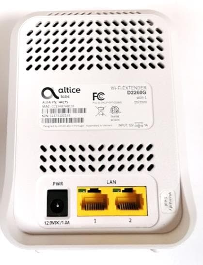
2ACJF-EXT-D2260G
Jan 14, 2021D2260G
Equipment Class
DTS - Digital Transmission System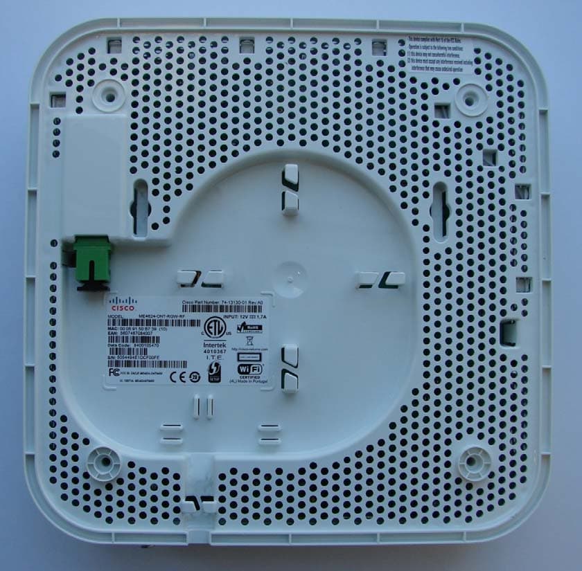
2ACJF-ME4624-ONTWRF
Mar 17, 2015Wireless Optical Network Termination (ONT) with RF Video Overlay Interface, for analog TV service
Equipment Class
DTS - Digital Transmission System