2ACMYAWSC25DIGITAL WIRELESS WEATHER PROOT CAMERA
Atoms Labs LLC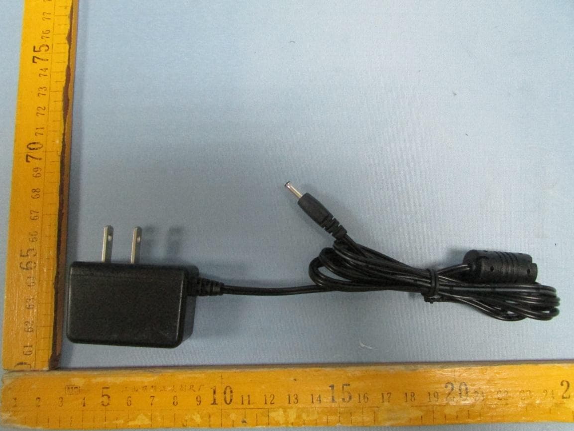
Click to zoom
Application Details
- Equipment Class
- DSS - Part 15 Spread Spectrum Transmitter
- Date of Grant
- Jul 16, 2014
- Application Purpose
- Original Equipment
- Date of Application
- Jul 16, 2014
- Equipment Note
- DIGITAL WIRELESS WEATHER PROOT CAMERA
- Frequency Range
- 2408.62500000 - 2473.87500000
- Company
- Atoms Labs LLC
- Country
- United States
Documents & Files
Document Text
Text extracted from the exhibit documents filed with the FCC. Open a document above to read the original.
Users Manual
QUICK START GUIDE KIT CONTENT Digital Wireless Camera Digital Wireless Receiver x 2x 1 Camera Antenna x 2 x2 Camera Stand x 3 Power Adapter Press and hold the reset button on the power cable for 5 seconds and the system will start the reset process. The system will restore to factory default and you may start the Wi-Fi setup. FACTORY DEFAULT SETTING CONNECTION DIAGRAM USB Cabel x 1 Screw Pack x 1 AV Cable x 1 Powering on/o the System Insert the memory card into the receiver if it’s not inserted. Press and Hold the POWER button for one second to power on the system. Press and hold the POWER button for two seconds to power o the system. After the system powers on, adjust the camera’s viewing position again if necessary. Pairing the Camera to Receiver (optional) The camera is paired to preset channel by default. The system supports up to 4 wireless cameras. If you are adding another camera to the system, please ensure its channel is set to a di erent channel to the existing camera(s). 1. Go to the Main Menu > Camera Setup(specify channel 1/2/3/4) > Press the Camera Pairing button 2. Press the pairing key ONCE on the camera Setting the Camera Channel (optional) The wireless camera is preset to channel 1 by default. You can also use the steps above to change the camera channel if necessary. Quick Start Guide x 1 FCC and IC Note: THIS DEVICE COMPLIES WITH PART 15 OF THE FCC RULES AND INDUSTRY CANADA LICENSE-EXEMPT RSS STANDARD(S). OPERATION IS SUBJECT TO THE FOLLOWING TWO CONDITIONS: (1) THIS DEVICE MAY NOT CAUSE HARMFUL INTERFERENCE, AND (2) THIS DEVICE MUST ACCEPT ANY INTERFERENCE RECEIVED, INCLUDING INTERFERENCE THAT MAY CAUSE UNDESIRED OPERATION. THE MANUFACTURER IS NOT RESPONSIBLE FOR ANY RADIO OR TV INTERFERENCE CAUSED BY UNAUTHORIZED MODIFICATIONS OR CHANGE TO THIS EQUIPMENT. SUCH MODIFICATIONS OR CHANGE COULD VOID THE USER’S AUTHORITY TO OPERATE THE EQUIPMENT. CAMERA INSTALLATION OPERATION SCREEN Main Menu Loosen up the thumb screw 2 Adjust proper view angle, then secure the joint with T-bolt. 3 RECORDER SETUP Camera Pairing Camera Brightness Adjustment Camera Activation Record Schedule Motion Detection Sensitivity Format Memory Card Setup Masking Area Record Time Date and Time TV Output Power Saving Multi Channels Idle Display Default 1. CAMERA SETUP 2. RECORDER SETUP 3. EVENT LIST 4. SYSTEM SETUP 5. ALARM BUZZER 6. PAN TILT ZOOM 7. SCAN ACTIVATED CAMERAS 8. MEMORY CARD OVERWRITE CAMERA SETUP EVENT LIST SYSTEM SETUP Press the MENU button to enter the MAIN MENU. The system highlights EVENT LIST by default. Tap the screen to navigate through the menus; the system highlights the EVENT LIST by default. The system will automatically exit the Main Menu when it is idle for 2 minutes. Secure the camera stand on a stable surface 1
Cover Letter(s)
Atoms Labs LLC Federal Communications Commission Authorization and Evaluation Division Date:2014/06/30 Confidentiality Request regarding application for certification of FCC ID: 2ACMYAWSC25. Pursuant to Sections 0.457 and 0.459 of the Commission’s Rules, we hereby request confidential treatment of information accompanying this application as outlined below: Exhibit Type File Name Schematics Block Diagram Operational Description 2ACMYAWSC25 _SCH.pdf 2ACMYAWSC25 _BlockDiagram.pdf 2ACMYAWSC25 _CircuitDescription.pdf The above materials contain trade secrets and proprietary information not customarily released to the public. The public disclosure of these materials may be harmful to the applicant and provide unjustified benefits to its competitors. The applicant understands that pursuant to Section 0.457 of the Rules, disclosure of this application and all accompanying documentation will not be made before the date of the Grant for this application. Sincerely, Atoms Labs LLC ................................................... Signature Daniel Steffy / Executive Vice Preaident of Sales
External Photos
Photographs - Constructional Details EUT –Appearance View Model: AWSC25 ANT. with RP-SMA connector Adapter 1–Appearance View Adapter 2–Appearance View Adapter 3–Appearance View
ID Label/Location Info
FCC and IC Label Location for model: AWSC25 This device complies with part 15 of the FCC rules and industry Canada license-exempt rss standard(s). Operation is subject to the following two conditions: (1) this device may not cause harmful interference, and (2) this device must accept any interference received, including interference that may cause undesired operation. FCC ID: 2ACMYAWSC25 IC: 12036A-AWSC25 This device complies with part 15 of the FCC rules and industry Canada license-exempt RSS standard(s). Operation is subject to the following two conditions: (1) this device may not cause harmful interference, and (2) this device must accept any interference received, including interference that may cause undesired operation.
ID Label/Location Info
FCC and IC Label Sample for model: AWSC25 This device complies with part 15 of the FCC rules and industry Canada license-exempt RSS standard(s). Operation is subject to the following two conditions: (1) this device may not cause harmful interference, and (2) this device must accept any interference received, including interference that may cause undesired operation. FCC ID: 2ACMYAWSC25 IC: 12036A-AWSC25 This device complies with part 15 of the FCC rules and industry Canada license-exempt RSS standard(s). Operation is subject to the following two conditions: (1) this device may not cause harmful interference, and (2) this device must accept any interference received, including interference that may cause undesired operation.
Internal Photos
EUT – Open View Model: AWSC25 ANT. connection point RF –Module View
Test Report
TEST REPORT Waltek Services (Shenzhen) Co.,Ltd. http://www.waltek.com.cn Page 1 of 59 Reference No. .................... : WTS14S0615312E FCC ID ................................ : 2ACMYAWSC25 Applicant ............................ : Atoms Labs LLC Address .............................. : 2670 Firewheel Dr. Suite D Flower Mound ,TX 75028 United States Manufacturer .................... : The same as above Address .............................. : The same as above Product Name .................... : Digital Wireless Weather Proot Camera Model No. ........................... : AWSC25 Standards .......................... : FCC CFR47 Part 15 Section 15.247:2012 Date of Receipt sample .... : Jun.24, 2014 Date of Test ....................... : Jun.25~27, 2014 Date of Issue ...................... : Jul.10, 2014 Test Result ......................... : Pass * *Remarks: The results shown in this test report refer only to the sample(s) tested, this test report cannot be reproduced, except in full, without prior written permission of the company. The report would be invalid without specific stamp of test institute and the signatures of compiler and approver. Prepared By: Waltek Services (Shenzhen) Co., Ltd. Address: 1/F., Fukangtai Building, West Baima Road, Songgang Street, Baoan District, Shenzhen, Guangdong, China Testing location: The same as above Tel :+86-755-83551033 Fax:+86-755-83552400 Compiled by: Approved by: Zero Zhou / Project Engineer Philo Zhong / Manager Reference No.: WTS14S0615312E Page 2 of 59 Waltek Services (Shenzhen) Co.,Ltd. http://www.waltek.com.cn 2 Test Summary Test Items Test Requirement Result Conducted Emission 15.207 PASS Radiated Emissions 15.205(a) 15.209 15.247(d) PASS Band Edge Measurement 15.205(c) 15.209 15.247(d) PASS 20dB Bandwidth 15.247(a)(1) PASS Maximum Peak Output Power 15.247(b)(1) PASS Channel Separated 15.247(a)(1) PASS Hopping Channel Number 15.247(a)(1)(iii) PASS Dwell time 15.247(a)(1)(iii) PASS Antenna Requirement 15.203 PASS Maximum Permissible Exposure (Exposure of Humans to RF Fields) 1.1307(b)(1) PASS Reference No.: WTS14S0615312E Page 3 of 59 Waltek Services (Shenzhen) Co.,Ltd. http://www.waltek.com.cn 3 Contents Page 1 COVER PAGE ........................................................................................................................................... 1 2 TEST SUMMARY ............................................................................................................................................. 2 3 CONTENTS ....................................................................................................................................................... 3 4 GENERAL INFORMATION ............................................................................................................................. 5 4.1 GENERAL DESCRIPTION OF E.U.T. ....................................................................................................... 5 4.2 DETAILS OF E.U.T. ................................................................................................................................ 5 4.3 DESCRIPTION OF SUPPORT UNITS ........................................................................................................ 5 4.4 TEST FACILITY ....................................................................................................................................... 5 4.5 TEST LOCATION ..................................................................................................................................... 5 5 EQUIPMENT USED DURING TEST ............................................................................................................. 6 5.1 EQUIPMENTS LIST ................................................................................................................................. 6 5.2 MEASUREMENT UNCERTAINTY .............................................................................................................. 6 5.3 TEST EQUIPMENT CALIBRATION............................................................................................................ 6 6 CONDUCTED EMISSIONS ............................................................................................................................. 7 6.1 E.U.T. OPERATION ................................................................................................................................ 7 6.2 TEST PROCEDURE ................................................................................................................................. 7 6.3 TEST SETUP .......................................................................................................................................... 7 6.4 CONDUCTED EMISSION TEST RESULT .................................................................................................. 8 7 RADIATED EMISSIONS ............................................................................................................................... 14 7.1 EUT OPERATION : ............................................................................................................................... 14 7.2 TEST SETUP ........................................................................................................................................ 15 7.3 SPECTRUM ANALYZER SETUP ............................................................................................................. 17 7.4 TEST PROCEDURE ............................................................................................................................... 17 7.5 CORRECTED AMPLITUDE & MARGIN CALCULATION ........................................................................... 18 7.6 SUMMARY OF TEST RESULTS ............................................................................................................. 19 8 BAND EDGE MEASUREMENT .........................................................................…
Text truncated - open the document above for the full version.
Test Setup Photos
Photographs – Model AWSC25 Test Setup Photograph –Conducted Emission Test Setup Photograph –Radiated Emissions Test Setup 12MHz~ 30MHz 30MHz ~ 1GHz 1GHz~25GHz
Contact Information
Applicant
Justin Wang
Test Firm
Waltek Services(Shenzhen) Co., Ltd.Philo zhong
Technical Specifications
| # | Rule Parts | Frequency Range | Power Output |
|---|---|---|---|
| 1 | 15C | 2.41 GHz - 2.47 GHz | 7.13 mW |
Other Applications from Atoms Labs LLC
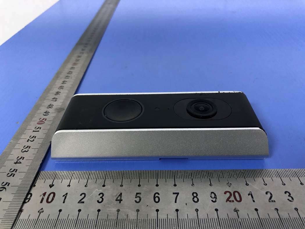
2ACMYAMZ30DB
Jul 21, 2020Wi-Fi Video Doorbell
Equipment Class
DTS - Digital Transmission System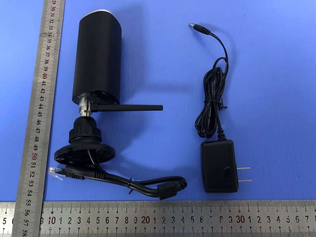
2ACMYAMZ10W
Jul 21, 2020Full HD 1080p IP CAM
Equipment Class
DTS - Digital Transmission System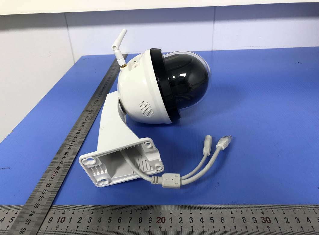
2ACMYAMZ20PT
Jul 21, 2020HD Outdoor PT Network Camera
Equipment Class
DTS - Digital Transmission System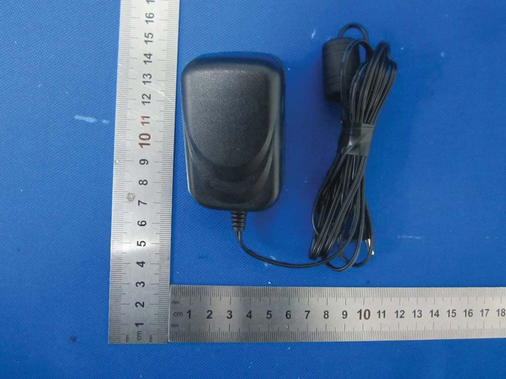
2ACMYAWF50
Jan 29, 2016720p Outdoor WiFi Camera
Equipment Class
DTS - Digital Transmission System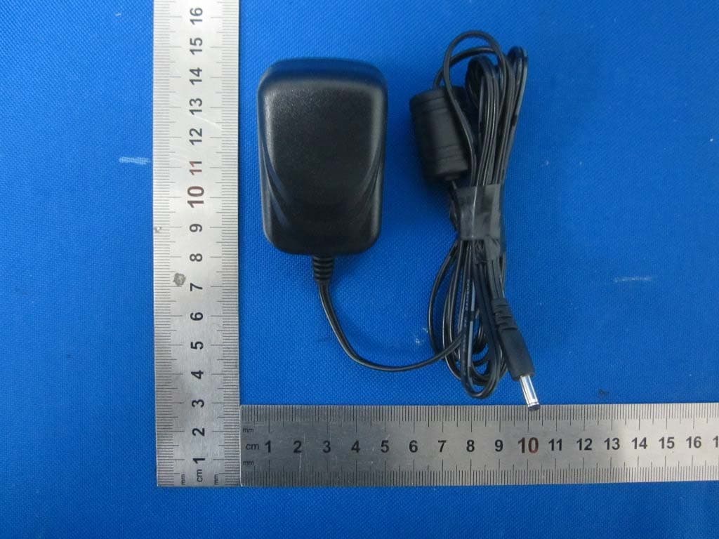
2ACMYAWSC35
Jan 29, 2016Digital Wireless Weather Proof Camera
Equipment Class
DSS - Part 15 Spread Spectrum Transmitter