2ACMYAWSC36Digital Wireless Weather Proof Camera
Atoms Labs LLC
Click to zoom
Application Details
- Equipment Class
- DSS - Part 15 Spread Spectrum Transmitter
- Date of Grant
- Aug 01, 2014
- Application Purpose
- Original Equipment
- Date of Application
- Aug 01, 2014
- Equipment Note
- Digital Wireless Weather Proof Camera
- Frequency Range
- 2414.25000000 - 2461.50000000
- Company
- Atoms Labs LLC
- Country
- United States
Documents & Files
Document Text
Text extracted from the exhibit documents filed with the FCC. Open a document above to read the original.
Users Manual
SD Card Slot Antenna PIR Stand QUICK START GUIDE KIT CONTENT : GETTING TO KNOW THE MONITOR AND CAMERA Press and hold the reset button on the power cable for 5 seconds and the system will start the reset process. The system will restore to factory default. FACTORY DEFAULT SETTING FCC Compliance Statement: This device complies with Part 15 of the FCC rules. Operation is subjected to the following two conditions: (1)this device may not cause harmful interference, and (2) this device must accept any interferencereceived, including interference that may cause undesired operation. Products with CE Marking comply with EMC Directive (2004/108/EC); Low Voltage Directive (73/23/EEC); R&TTE (1999/5/EC); ROHS Directive (2011/65/EU) issued by the Commission of the European Community. Compliance with these directives implies conformity to the following European Norms: EMC: EN 301 489 LVD: EN 60950 Radio: EN 300 328 If the camera system no longer functions or can no longer be repaired, it must be disposed of according to the valid statutory regulations. Disposal of spent batteries/accumulators: Wireless Camera w/ stand Wireless Touch Screen LCD Monitor w/ Cradle x 2x 1 Camera Antenna x 2 x 3 Power Adapter You are required by law (Battery Ordinance) to return all spent batteries and accumulators. Disposing of spent batteries/accumulators with common household waste is prohibited! Batteries/accumulators that contain hazardous substances are marked with the symbols on the side. These symbols indicate that it is prohibited to dispose of these batteries/accumulators in the household waste. The abbreviations for the respective heavy metals are: Cd=cadmium, Hg=mercury, Pb=lead. You can return spent batteries and accumulators that can no longer be charged to the designated collection points in your community, outlets or wherever batteries or accumulators are sold. Following these instructions will allow you to ful ll the legal requirements and contribute to the protection of our environment! Internet CableScrew Pack x 1x 1 Quick Start Guide x 1 Pairing the Camera to Receiver (optional) The system supports up to 4 wireless cameras. If you are adding another camera to the system, please ensure its channel is set to a di erent channel to the existing camera(s). 1. Go to the Main Menu>Camera Setup (specify channel 1/2/3/4)>Press the Camera Pairing button 2. Press the pairing key ONCE on the camera Setting the Camera Channel (optional) The wireless camera is preset to channel 1 by default. You can also use the steps above to change the camera channel if necessary. CAMERA INSTALLATION Loosen up the thumb screwAdjust proper view angle, then secure the joint with T-bolt. Secure the camera stand on a stable surface 123 Receiver (back/side)Camera This device complies with Industry Canada licence-exempt RSS standard(s). Operation is subject to the following two conditions: (1) this device may not cause interference, and (2) this device must accept any interference, including interference that may cause undesired operation of the device. Le présent appareil est conforme aux CNR d'Industrie Canada applicables aux appareils radio exempts de licence. L'exploitation est autorisée aux deux conditions suivantes : (1) l'appareil ne doit pas produire de brouillage, et (2) l'utilisateur de l'appareil doit accepter tout brouillage radioélectrique subi, même si le brouillage est susceptible d'en compromettre le fonctionnement. L'antenne (s) utilisé pour cet émetteur doit être installé pour fournir une distance de séparation d'au moins 20 cm de toute personne et ne doit pas être co- localisées ou opérant dans conjointement avec une autre antenne ou émetteur. Changes or modifications not expressly approved by the party responsible for compliance could void the user's authority to operate the equipment. The antenna(s) used for this transmitter must be installed to provide a separation distance of at least 20 cm from all persons and must not be co-located or operating in conjunction with any other antenna or transmitter. OPERATION SCREEN Live Screen Displays The Live screen displays in 2 views - Quad View or Full View. Quad View displays the images in 4 quadrants (only display camera that is ON). Tap a quadrant to display single camera view / full view. Tap on that image again to return to Quad View. Manual Recording 1. On the Live screen, tapfor the camera to begin recording. 2. Tap it again to stop recording. Playback the Recorded Video From the pop-up menu, tap the following icons Camera Mode Volume System Settings SD Capacity Battery Capacity Camera Number Connecting to the Record Status Record Status Connecting to the Internet Internet Connected Remote View Motion Scheduled Pop Up Menu Tab No SD Card Indicator Zoom Zoom Feature To zoom into a particular area, 1. Go to full view, then tap to activate zoom mode. 2. Select the zone by tapping the zone area to view zoom in screen. From the pop-up menu, tap the following icons Main Screen
External Photos
Antenna 1 Antenna 2 Adapter1 Adapter2 Adapter1 Adapter2
ID Label/Location Info
35*20mm FCC ID:2ACMYAWSC36 Input: Model Number: AWSC36 IC: 12036A-AWSC36 THIS DEVICE COMPLIES WITH PART 15 OF THE FCC RULES. OPERATION IS SUBJECT TO THE FOLLOWING TWO CONDITIONS: (1)THIS DEVICE MAY NOT CAUSE HARMFUL INTERFERENCE, AND (2)THIS DEVICE MUST ACCEPT ANY INTERFERENCE THAT MAY CAUSE UNDESIRED OPERATION.PRIVACY OF COMMUNICATIONS MAY NOT BE ENSURED WHEN USING THIS DEVICE. 5V 1A Digital Wireless Weather Proof Camera Made in China FCC ID:2ACMYAWSC36 Input: Model Number: AWSC36 IC: 12036A-AWSC36 THIS DEVICE COMPLIES WITH PART 15 OF THE FCC RULES. OPERATION IS SUBJECT TO THE FOLLOWING TWO CONDITIONS: (1)THIS DEVICE MAY NOT CAUSE HARMFUL INTERFERENCE, AND (2)THIS DEVICE MUST ACCEPT ANY INTERFERENCE THAT MAY CAUSE UNDESIRED OPERATION.PRIVACY OF COMMUNICATIONS MAY NOT BE ENSURED WHEN USING THIS DEVICE. 5V 1A Digital Wireless Weather Proof Camera Made in China
RF Exposure Info
FCC ID:2ACMYAWSC36 RF Exposure Evaluation Limits The criteria listed in the following table shall be used to evaluate the environment impact of human exposure to radio frequency (RF) radiation as specified in 1.1307(b) Limits for Maximum Permissible Exposure (MPE) Frequency range (MHz) Electric field strength (V/m) Magnetic field strength (A/m) Power density (mW/cm 2 ) Averaging time (minutes) (A) Limits for Occupational/Controlled Exposures 0.3–3.0 614 1.63 *(100) 6 3.0–30 1842/f 4.89/f *(900/f 2 ) 6 30–300 61.4 0.163 1.0 6 300–1500 f/300 6 1500–100,000 5 6 (B) Limits for General Population/Uncontrolled Exposure 0.3–1.34 614 1.63 *(100) 30 1.34–30 824/f 2.19/f *(180/f 2 ) 30 30–300 27.5 0.073 0.2 30 300–1500 f/1500 30 1500–100,000 1.0 30 f = frequency in MHz Friis transmission formula: Pd = (Pout*G)/(4*pi*r 2 ) Where Pd = power density in mW/cm 2 , Pout = output power to antenna in mW; G = gain of antenna in linear scale, Pi = 3.1416; R = distance between observation point and center of the radiator in cm Pd id the limit of MPE, 1 mW/cm 2 . If we know the maximum gain of the antenna and the total power input to the antenna, through the calculation, we will know the distance r where the MPE limit is reached. Test Procedure Software provided by client enabled the EUT to transmit and receive data at lowest, middle and highest channel individually. Test Result of RF Exposure Evaluation Channel Output power to antenna (mW) Power Density at R=20cm (mW/cm 2 ) Limit (mW/cm 2 ) Result Lowest (2412MHz) 29.648 0.01177 1.0 PASS Middle (2437MHz) 31.623 0.01255 1.0 PASS Highest (2462MHz) 31.477 0.01249 1.0 PASS Remark: antenna gain=3.0 dBi
Test Report
Global United Technology Services Co., Ltd. Report No.: GTSE14060105901 Authorized Signature: Robinson Lo Laboratory Manager This report details the results of the testing carried out on one sample. The results contained in this test report do not relate to other samples of the same product and does not permit the use of the GTS product certification mark. The manufacturer should ensure that all products in series production are in conformity with the product sample detailed in this report. This report may only be reproduced and distributed in full. If the product in this report is used in any configuration other than that detailed in the report, the manufacturer must ensure the new system complies with all relevant standards. Any mention of GTS or testing done by GTS in connection with, distribution or use of the product described in this report must be approved by GTS in writing. This document cannot be reproduced except in full, without prior written approval of the Company. Any unauthorized alteration, forgery or falsification of the content or appearance of this document is unlawful and offenders may be prosecuted to the fullest extent of the law. Unless otherwise stated the results shown in this test report refer only to the sample(s) tested and such sample(s) are retained for 90 days only. 1 Cover Page FCC Report Applicant: Atoms Labs LLC Address of Applicant: 2670 Firewheel Dr. Suite D Flower Mound, TX 75028 United States Equipment Under Test (EUT) Product Name: Digital Wireless Weather Proof Camera Model No.: AWSC36 FCC ID: 2ACMYAWSC36 Applicable standards: FCC CFR Title 47 Part 15 Subpart C Section 15.247:2013 Date of sample receipt: June 24, 2014 Date of Test: July 03-08, 2014 Date of report issued: July 08, 2014 Test Result : PASS * * In the configuration tested, the EUT complied with the standards specified above. Report No.: GTSE14060105901 Global United Technology Services Co., Ltd. Project No.: GTSE140601059RF 2nd Floor, Block No.2, Laodong Industrial Zone, Xixiang Road Baoan District, Shenzhen, China 518102 Telephone: +86 (0) 755 2779 8480 Fax: +86 (0) 755 2779 8960 Page 2 of 47 2 Version Version No. Date Description 00 July 08, 2014 Original Prepared By: Date: July 08, 2014 Project Engineer Check By: Date: July 08, 2014 Reviewer Report No.: GTSE14060105901 Global United Technology Services Co., Ltd. Project No.: GTSE140601059RF 2nd Floor, Block No.2, Laodong Industrial Zone, Xixiang Road Baoan District, Shenzhen, China 518102 Telephone: +86 (0) 755 2779 8480 Fax: +86 (0) 755 2779 8960 Page 3 of 47 3 Contents Page 1 COVER PAGE .......................................................................................................................................... 1 2 VERSION .................................................................................................................................................. 2 3 CONTENTS .............................................................................................................................................. 3 4 TEST SUMMARY ..................................................................................................................................... 4 5 GENERAL INFORMATION ...................................................................................................................... 5 5.1 CLIENT INFORMATION .......................................................................................................................... 5 5.2 GENERAL DESCRIPTION OF EUT ......................................................................................................... 5 5.3 TEST MODE ........................................................................................................................................ 7 5.4 TEST FACILITY .................................................................................................................................... 7 5.5 TEST LOCATION .................................................................................................................................. 7 5.6 OTHER INFORMATION REQUESTED BY THE CUSTOMER ......................................................................... 7 5.7 DESCRIPTION OF SUPPORT UNITS ....................................................................................................... 7 6 TEST INSTRUMENTS LIST ..................................................................................................................... 8 7 TEST RESULTS AND MEASUREMENT DATA ...................................................................................... 9 7.1 ANTENNA REQUIREMENT ..................................................................................................................... 9 7.2 CONDUCTED EMISSIONS ................................................................................................................... 11 7.3 CONDUCTED PEAK OUTPUT POWER .................................................................................................. 14 7.4 20DB EMISSION BANDWIDTH ............................................................................................................. 16 7.5 CARRIER FREQUENCIES SEPARATION ................................................................................................ 18 7.6 HOPPING CHANNEL NUMBER ............................................................................................................. 20 7.7 DWELL TIME ..................................................................................................................................... 21 7.8 BAND EDGE ...................................................................................................................................... 25 7.8.1 Conducted Emission Method ..................................................................................................... 25 7.8.2 Radiated Emission Method ...........................................................................…
Text truncated - open the document above for the full version.
Test Setup Photos
Radiated Emission Conducted Emission
Contact Information
Applicant
Justin Wang
Test Firm
Global United Technology Service Co., LtdRobinson Lo
Technical Specifications
| # | Rule Parts | Frequency Range | Power Output |
|---|---|---|---|
| 1 | 15C | 2.41 GHz - 2.46 GHz | 31.60 mW |
Other Applications from Atoms Labs LLC
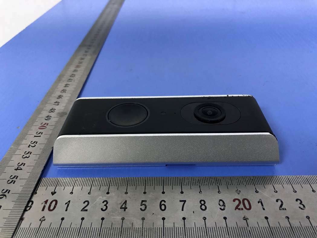
2ACMYAMZ30DB
Jul 21, 2020Wi-Fi Video Doorbell
Equipment Class
DTS - Digital Transmission System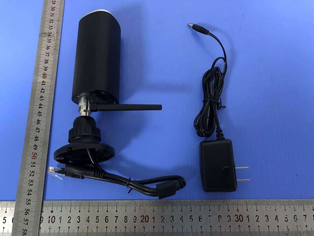
2ACMYAMZ10W
Jul 21, 2020Full HD 1080p IP CAM
Equipment Class
DTS - Digital Transmission System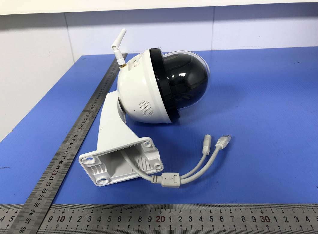
2ACMYAMZ20PT
Jul 21, 2020HD Outdoor PT Network Camera
Equipment Class
DTS - Digital Transmission System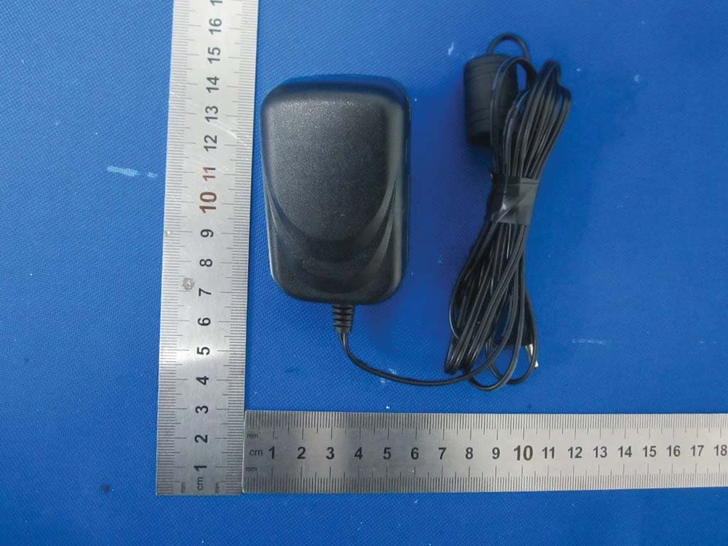
2ACMYAWF50
Jan 29, 2016720p Outdoor WiFi Camera
Equipment Class
DTS - Digital Transmission System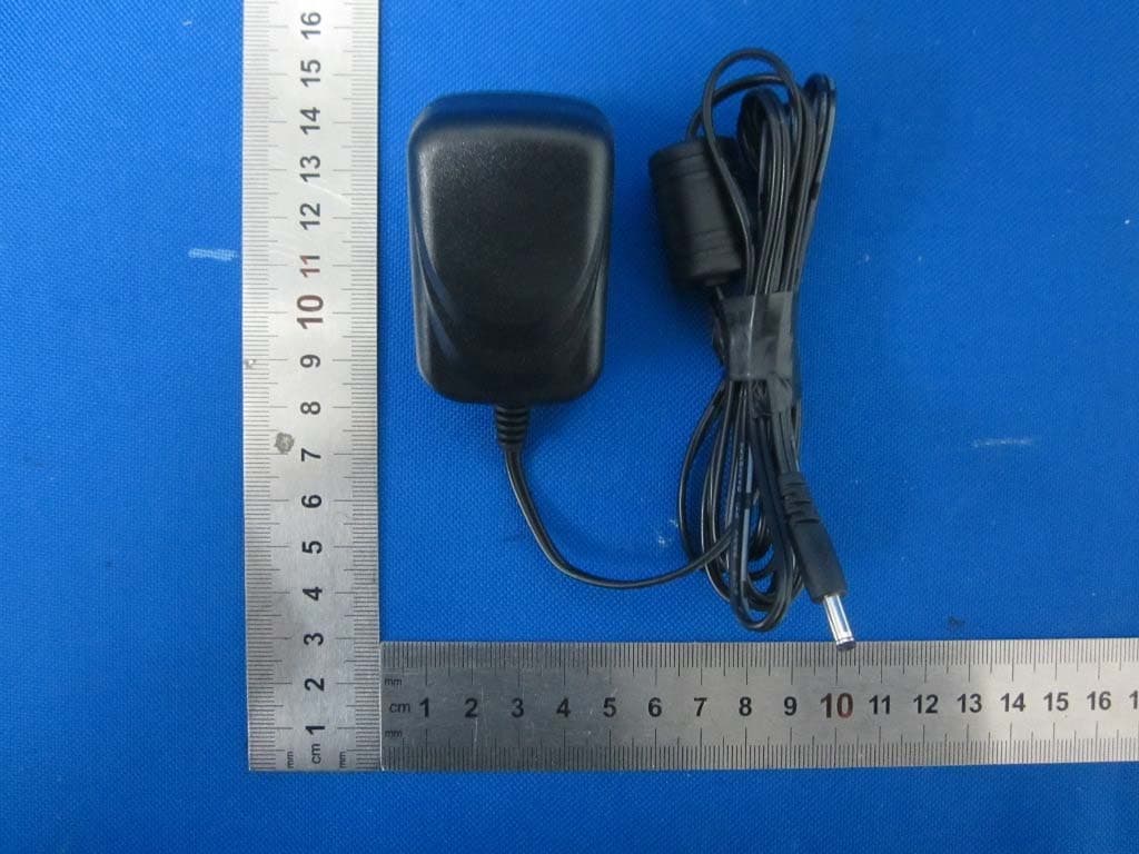
2ACMYAWSC35
Jan 29, 2016Digital Wireless Weather Proof Camera
Equipment Class
DSS - Part 15 Spread Spectrum Transmitter