FCCID.CO- FCC ID Database
HomeCompaniesEquipment ClassesSearch

© 2026 FCC ID Database. All rights reserved.

AboutContactData sourced from FCC public records
  1. Home/
  2. AS America, Inc. d/b/a Lixil Americas/
  3. 2ACNC-607XXXX-XXX

2ACNC-607XXXX-XXXIOT Sensor for Urinals and Toilet

AS America, Inc. d/b/a Lixil Americas
IOT Sensor for Urinals and Toilet - FCC ID 2ACNC-607XXXX-XXX - AS America, Inc. d/b/a Lixil Americas
Click to zoom

Application Details

Equipment Class
DTS - Digital Transmission System
Date of Grant
Jul 18, 2023
Application Purpose
Original Equipment
Date of Application
Jul 18, 2023
Equipment Note
IOT Sensor for Urinals and Toilet
Frequency Range
2402.00000000 - 2480.00000000
Company
AS America, Inc. d/b/a Lixil Americas
Country
United States

Documents & Files

Select a file to view
Users Manual

↗
↗
↗
↗

Attestation Statements

↗
↗
↗

Cover Letter(s)

↗
↗

External Photos

↗

ID Label/Location Info

↗

Internal Photos

↗

Operational Description

↗

RF Exposure Info

↗

Test Report

↗
↗
↗
↗

Test Setup Photos

↗
↗

Document Text

Text extracted from the exhibit documents filed with the FCC. Open a document above to read the original.

Users Manual

M985145 SKU# 607X121 EN (5/23) 6072121/607B121 American Standard is devoted to making life, in the heart of your home, better every day... ...so, thank you for inviting us in! With the very best in kitchen and bathroom products, we are here to help make your life happier, healthier and simpler. Our commitment to quality, innovation and performance has made us part of your everyday routine for nearly 150 years, and we look forward to being a part of your life for many years to come. Learn more at www.AmericanStandard.com REGISTER YOUR WARRANTY Try the easy-scan QR code to quickly enter your information or find your product’s detailed warranty here: www.AmericanStandard.com/warranty Registering allows you to keep your product information safe, and us the ability to contact you in the event of a product recall or any news about your purchase. And if ever you have a question or need help...? Call us at 1-855-815-0004 OWNERS MANUAL IoT DetectLnk ™ Exposed Toilet Flush Valve 6072121 / 607B121 Image shown may vary from product purchased. INSIDE THE BOX (BATTERY VERSION) POWER KITS SOLD SEPARATELY 60780XX FOR BATTERY VERSIONS Vacuum Breaker Tube Stop Valve Flush Valve INSIDE THE BOX (AC VERSION) Hard-Wired AC Power Kit Hard-Wired AC & Multi-AC Power Kit PK00.HAC / PK00.BBU PK00.MAC / PK00.HAC PK00.BBU POWER KITS SOLD SEPARATELY 607BXXX/607B0XX FOR AC VERSIONS Vacuum Breaker Tube Stop Valve Flush Valve NOTE TO INSTALLER: Please give this manual to the customer after installation. To learn more about American Standard Selectronic ® Products visit our website at: www.americanstandard-us.com or e-mail us at: [email protected] For Parts, Service, Warranty or other Assistance, please call (844) CRT-TEAM / (844) 278-8326 (In Toronto Area only: 1-905-306-1093) PRIOR TO INSTALLATION Note: Prior to installing the DetectLnk™ Flush Valve the following items must be installed. 1. Urinal/Toilet 2. Drain line 3. Water supply line IMPORTANT: • All plumbing and electrical wiring should be installed in accordance with applicable codes and regulations. • The use of water hammer arrestors is strongly recommended for commercial applications. All piping behind the walls should be properly secured and fastened. • Water supply lines must be sized to provide an adequate volume of water for each fixture. • Flush all water lines prior to operation Dirt and debris can cause flush valve to run continuously. • With the exception of Stop Valve Inlet, DO NOT use pipe sealant or plumbing grease on any valve component or coupling! • Protect the chrome or special finish on the Flushometer. DO NOT USE toothed tools on finished surfaces to install or service these valves. Also see “Care and Cleaning” section of this manual. • This product contains mechanical and/or electrical components that are subject to normal wear. These components should be checked on a regular basis and replaced as needed to maintain the valve’s performance. Consult fixture manufacturer for minimum pressure requirements. Most High Efficiency water closets require a minimum flowing pressure of 25 psi (172 kPa). Many building codes and the ASME A112.19.2 fixture standard list Maximum static water pressure as 80 PSI (552 kPa). 10' RECOMMENDED TOOLS Teflon Tape Installation steps will indicate which tools should be used with asscociated letter A Flat Blade Screwdriver B Adjustable Wrench C Hacksaw D Tape Measure E Tubing Cutter F File G 2.5 & 1.5 mm Hex Wrench H Solder & Torch I Note: Install Optional Sweat Adapter (Supplied) for copper pipe supply line. 1. Measure the distance (A) from the finished wall to the center of the inlet spud on the fixture. 2. Cut the supply pipe 1-1/4” (A-B=C) shorter than the measurement taken in Step 1. File any rough edges off the end of the supply pipe. 3. Clean the end of the supply pipe. Push the threaded Adapter until it is seated against the internal stop. Sweat the Adapter to the pipe. CENTER LINE OF FIXTURE SPUD FINISHED WALL FILE EDGES SOLDER ADAPTER ADAPTER 32mm (1-1/4") A (A-B)= B C CLEAN 1 INSTALL SWEAT ADAPTER F 2 INSTALL COVER TUBE, WALL ESCUTCHEON AND STOP VALVE Turn off hot and cold water supplies before beginning. Fig. 4a Fig. 4b Fig. 4c 1 1 4 2 3 TEFLON TAPE FINISHED WALL X X 2 FLUSH VAVLE INSTALLATION 1. Measure from finished wall to first thread of Adapter or threaded supply pipe (dimension “X”). Cut COVER TUBE (1) to length (X). Apply Teflon Tape to the threaded end of the Adapter or supply pipe. 2. Push WALL ESCUTCHEON (2) onto the COVER TUBE (1). Slide both onto the SUPPLY PIPE (3). 3. Push the COVER TUBE (1) in to expose the threads of the supply pipe. With a wrench thread the STOP VALVE (4) onto the SUPPLY PIPE (3). Align and tighten. 4. Pull COVER TUBE (1) against STOP VALVE (4) and push WALL ESCUTCHEON (2) against finished wall. GIDE ACDF 3 FLUSH OUT SUPPLY LINES 1 CLOCKWISE CLOSES STOP VALVE COUNTER-CLOCKWISE OPENS STOP VALVE REMOVE COVER 2 2 B 1. Remove STOP VALVE COVER (1) from STOP VALVE (2). 2. Open STOP VALVE (2) with a flat blade screwdriver. 3. Tu r n on water supply to flush line of any debris or sediment. 4. Close STOP VALVE (2) and replace STOP VALVE COVER (1). 2 4 1 3 4a INSTALL VACUUM BREAKER TUBE: APPLICABLE FOR STANDARD CERAMICS Note: Step 4a is only applicable if using standard ceramics. If using IoT Ceramics, skip to step 4b. 1. Insert VACUUM BREAKER TUBE (1) through HEX NUT (4), FLUSH VALVE BOTTOM COVER (2), and SPUD COVER (3). 2. Thread SPUD COVER (3) on to the toilet base. Note: Ensure that the O-ring is properly seated in the base of HEX NUT (4). C 1 2 3 4b 1. Slide SPUD COVER (1) over HEX NUT (2). 2. Secure SPUD COVER (1) by tightening SET SCREW (3). H INSTALL VACUUM BREAKER TUBE: APPLICABLE WITH ASA IOT CERAMICS 2 6 5 1 3 4 CD 4 7 Note: Step 4b is only applicable if using ASA IoT Ceramics. Otherwise, refer to step 4a. 1. Separate HEX NUT (4) from SPUD COVER (7). 2. Thread WIRE (5) through FLUSH VALVE BOTTOM COVER (2) and SPUD COVER (3). 3. Insert VACUUM BREAKER TUBE (1) through t…

Text truncated - open the document above for the full version.

Users Manual

M985146 EN (7/23) 607B121/607B051/607B013/6078013/6078051 American Standard is devoted to making life, in the heart of your home, better every day... ...so, thank you for inviting us in! With the very best in kitchen and bathroom products, we are here to help make your life happier, healthier and simpler. Our commitment to quality, innovation and performance has made us part of your everyday routine for nearly 150 years, and we look forward to being a part of your life for many years to come. Learn more at www.AmericanStandard.com REGISTER YOUR WARRANTY Try the easy-scan QR code to quickly enter your information or find your product’s detailed warranty here: www.AmericanStandard.com/warranty Registering allows you to keep your product information safe, and us the ability to contact you in the event of a product recall or any news about your purchase. And if ever you have a question or need help...? Call us at 1-855-815-0004 Hard-Wired AC Power Kit Hard-Wired AC & Multi-AC Power Kit PK00.HAC / PK00.BBU PK00.MAC / PK00.HAC PK00.BBU POWER KITS SOLD SEPARATELY 607BXXX/607B0XX FOR AC VERSIONS POWER KITS SOLD SEPARATELY 6072121 FOR BATTERY VERSIONS Image shown may vary from product purchased. OWNERS MANUAL IoT DetectLnk ™ Exposed Urinal Flush Valve 607B121 / 607B051 / 607B013 / 6078013 / 6078051 INSIDE THE BOX (BATTERY VERSION) POWER KITS SOLD SEPARATELY 60780XX FOR BATTERY VERSIONS Vacuum Breaker Tube Stop Valve Flush Valve INSIDE THE BOX (AC VERSION) Hard-Wired AC Power Kit Hard-Wired AC & Multi-AC Power Kit PK00.HAC / PK00.BBU PK00.MAC / PK00.HAC PK00.BBU POWER KITS SOLD SEPARATELY 607BXXX/607B0XX FOR AC VERSIONS Vacuum Breaker Tube Stop Valve Flush Valve NOTE TO INSTALLER: Please give this manual to the customer after installation. To learn more about American Standard Selectronic ® Products visit our website at: www.americanstandard-us.com or e-mail us at: [email protected] For Parts, Service, Warranty or other Assistance, please call (844) CRT-TEAM / (844) 278-8326 (In Toronto Area only: 1-905-306-1093) PRIOR TO INSTALLATION Note: Prior to installing the DetectLnk™ Flush Valve the following items must be installed. 1. Urinal/Toilet 2. Drain line 3. Water supply line IMPORTANT: • All plumbing and electrical wiring should be installed in accordance with applicable codes and regulations. • The use of water hammer arrestors is strongly recommended for commercial applications. All piping behind the walls should be properly secured and fastened. • Water supply lines must be sized to provide an adequate volume of water for each fixture. • Flush all water lines prior to operation Dirt and debris can cause flush valve to run continuously. • With the exception of Stop Valve Inlet, DO NOT use pipe sealant or plumbing grease on any valve component or coupling! • Protect the chrome or special finish on the Flushometer. DO NOT USE toothed tools on finished surfaces to install or service these valves. Also see “Care and Cleaning” section of this manual. • This product contains mechanical and/or electrical components that are subject to normal wear. These components should be checked on a regular basis and replaced as needed to maintain the valve’s performance. Consult fixture manufacturer for minimum pressure requirements. Most High Efficiency water closets require a minimum flowing pressure of 25 psi (172 kPa). Many building codes and the ASME A112.19.2 fixture standard list Maximum static water pressure as 80 PSI (552 kPa). 10' RECOMMENDED TOOLS Teflon Tape Installation steps will indicate which tools should be used with asscociated letter A Flat Blade Screwdriver B Adjustable Wrench C Hacksaw D Tape Measure E Tubing Cutter F File G 2.5 & 1.5 mm Hex Wrench H Solder & Torch I Note: Install Optional Sweat Adapter (Supplied) for copper pipe supply line. 1. Measure the distance (A) from the finished wall to the center of the inlet spud on the fixture. 2. Cut the supply pipe 1-1/4” (A-B=C) shorter than the measurement taken in Step 1. File any rough edges off the end of the supply pipe. 3. Clean the end of the supply pipe. Push the threaded Adapter until it is seated against the internal stop. Sweat the Adapter to the pipe. CENTER LINE OF FIXTURE SPUD FINISHED WALL FILE EDGES SOLDER ADAPTER ADAPTER 32mm (1-1/4") A (A-B)= B C CLEAN 1 INSTALL SWEAT ADAPTER F 2 INSTALL COVER TUBE, WALL ESCUTCHEON AND STOP VALVE Turn off hot and cold water supplies before beginning. Fig. 4a Fig. 4b Fig. 4c 1 1 4 2 3 TEFLON TAPE FINISHED WALL X X 2 FLUSH VAVLE INSTALLATION 1. Measure from finished wall to first thread of Adapter or threaded supply pipe (dimension “X”). Cut COVER TUBE (1) to length (X). Apply Teflon Tape to the threaded end of the Adapter or supply pipe. 2. Push WALL ESCUTCHEON (2) onto the COVER TUBE (1). Slide both onto the SUPPLY PIPE (3). 3. Push the COVER TUBE (1) in to expose the threads of the supply pipe. With a wrench thread the STOP VALVE (4) onto the SUPPLY PIPE (3). Align and tighten. 4. Pull COVER TUBE (1) against STOP VALVE (4) and push WALL ESCUTCHEON (2) against finished wall. GIDE ACDF 3 FLUSH OUT SUPPLY LINES 1 CLOCKWISE CLOSES STOP VALVE COUNTER-CLOCKWISE OPENS STOP VALVE REMOVE COVER 2 2 B 1. Remove STOP VALVE COVER (1) from STOP VALVE (2). 2. Open STOP VALVE (2) with a flat blade screwdriver. 3. Tu r n on water supply to flush line of any debris or sediment. 4. Close STOP VALVE (2) and replace STOP VALVE COVER (1). 2 4 1 3 4a INSTALL VACUUM BREAKER TUBE: APPLICABLE FOR STANDARD CERAMICS Note: Step 4a is only applicable if using standard ceramics. If using IoT Ceramics, skip to step 4b. 1. Insert VACUUM BREAKER TUBE (1) through HEX NUT (4), FLUSH VALVE BOTTOM COVER (2), and SPUD COVER (3). 2. Thread SPUD COVER (3) on to the toilet base. Note: Ensure that the O-ring is properly seated in the base of HEX NUT (4). C 4b INSTALL VACUUM BREAKER TUBE: APPLICABLE WITH ASA IOT CERAMICS 2 6 5 1 3 4 Note: Step 4b is only applicable if using ASA IoT Ceramics or the hard-wired power option. Otherwise…

Text truncated - open the document above for the full version.

Users Manual

M985165 EN (7/23) 607B222/607B301/607B305 American Standard is devoted to making life, in the heart of your home, better every day... ...so, thank you for inviting us in! With the very best in kitchen and bathroom products, we are here to help make your life happier, healthier and simpler. Our commitment to quality, innovation and performance has made us part of your everyday routine for nearly 150 years, and we look forward to being a part of your life for many years to come. Learn more at www.AmericanStandard.com REGISTER YOUR WARRANTY Try the easy-scan QR code to quickly enter your information or find your product’s detailed warranty here: www.AmericanStandard.com/warranty Registering allows you to keep your product information safe, and us the ability to contact you in the event of a product recall or any news about your purchase. And if ever you have a question or need help...? Call us at 1-855-815-0004 Hard-Wired AC Power Kit Hard-Wired AC & Multi-AC Power Kit PWRX Power Kit PK00.WRK PIOT.HAC PK00.BBU PIOT.MAC / PIOT.HAC PK00.BBU POWER KITS SOLD SEPARATELY 10' INSIDE THE BOX RECOMMENDED TOOLS Teflon Tape Installation steps will indicate which tools should be used with asscociated letter A Vacuum Breaker Flush Connection (Concealed Back Spud) Flush Valve Body Assembly Flat Blade Screwdriver B Adjustable Wrench C Hacksaw D Tape Measure E Tubing Cutter F File G 2.5 & 1.5 mm Hex Wrench H Solder & Torch I Rubber Wrench J OWNERS MANUAL IoT DetectLnk ™ Flush Valve, Piston-Type for Toilet & Urinal 607B222 / 607B301 / 607B305 Image shown may vary from product purchased. Cover Plate with Sensor Electrical Box Stop Valve Sweat Adapter NOTE TO INSTALLER: Please give this manual to the customer after installation. To learn more about American Standard Selectronic ® Products visit our website at: www.americanstandard-us.com or e-mail us at: [email protected] For Parts, Service, Warranty or other Assistance, please call (844) CRT-TEAM / (844) 278-8326 (In Toronto Area only: 1-905-306-1093) 1 ROUGHING-IN DIMENSIONS 2 PRIOR TO INSTALLATION INSTALLATION INSTRUCTIONS 240mm MAX. (9-1/2) MAX. -C-L--C-L- 51mm (2) 70mm (2-3/4) DIA. 25mm (1) MAX. 160mm (6-1/4) OVERRIDE BUTTON 160mm (6-1/4) 127mm X 127mm (5X5 CUTOUT FOR BOX) 128mm MAX. (5) MAX. 400mm MAX. (15-3/4) MAX. FOR LOCATION OF INLET SUPPLY ON BACK INLET FIXTURES AND CORRECT HEIGHT FROM FINISHED FLOOR, REFER TO FIXTURE INSTRUCTION SHEET. FINISHED WALL CONCEALED BACK SPUD TOILET EXPOSED BACK SPUD TOILET TOP SPUD TOILET TOP OF FIXTURE FINISHED FLOOR FINISHED FLOOR FINISHED FLOOR TOP OF FIXTURE SENSOR SUPPLY (1) NPT 108mm-134mm (4-1/4 TO 5-1/4) *Note: The Critical Line (-C-L-) on Vacuum Breaker must typically be 6 " (152mm) min. above fixture. Consult Codes for details. 51mm (2) 51mm (2) WALL THICKNESS 15 ̊ TOP OF FIXTURE 450mm MAX. (17-3/4) MAX. DETECTION ZONE 400mm-800mm (Factory Setting: 400mm) 152mm MIN. (6) MIN. *-C-L- 152mm MIN. (6) MIN. *-C-L- 360mm MAX. (14-3/16) MAX. GENERAL DESCRIPTION: SELECTRONIC ® PROXIMITY TOILET FLUSH VALVE Concealed Flushometer for 1-1/2" Top Spud Fixtures CAUTION: Use only American Standard supplied transformers and cable sets. Using non-AS supplied cables, or cutting, splicing or modifying any components will void the warranty. Note: Prior to installing the Selectronic™Flush Valve the following items must be installed. 1. Toilet 2. Drain line 3. Water supply line IMPORTANT: • All plumbing and electrical wiring should be installed in accordance with applicable codes and regulations. • The use of water hammer arrestors is strongly recommended for commercial applications. All piping behind the walls should be properly secured and fastened. • Water supply lines must be sized to provide an adequate volume of water for each fixture. • Flush all water lines prior to operation (See Step 3). Dirt and debris can cause flush valve to run continuously. • With the exception of Stop Valve Inlet, DO NOT use pipe sealant or plumbing grease on any valve component or coupling! • Protect the chrome or special finish on the Flushometer. DO NOT USE toothed tools on finished surfaces to install or service these valves. Also see “Care and Cleaning” section of this manual. • This product contains mechanical and/or electrical components that are subject to normal wear. These components should be checked on a regular basis and replaced as needed to maintain the valve’s performance. 1 INSTALL ELECTRICAL BOX 3 FLUSH OUT SUPPLY LINES FLUSH VALVE INSTALLATION Fig.3 (TOP SPUD FIXTURE ILLUSTRATED) 3 2 1 *FOR HOLE LOCATION OF OUTLET PIPE ON BACK INLET FIXTURES, REFER TO FIXTURE BEING INSTALLED FOR CORRECT HEIGHT FROM FINISHED FLOOR 127mm (5) 127mm (5) TOP T O P 128mm MAX. (5) MAX. 360mm MAX. (14-3/16) MAX. Fig. 4 2 1 FILE EDGES CLEAN & SOLDER TO ADAPTER (1) 115mm-134mm (4-1/2 TO 5-1/4) STOP VALVE (1" NPT) STOP VALVE OUTLET T O P 2 1 CLOCKWISE CLOSES STOP VALVE COUNTER-CLOCKWISE OPENS STOP VALVE 1. Open STOP VALVE (1). 2. Tu r n on water supply line to flush line of any debris or sediment. 3. Close STOP VALVE (1) and turn off water supply line. 2 INSTALL SWEAT ADAPTER Note: Stop Valve inlet is 1” NPT. For optional sweat connection, install Sweat Adapter (1) (Supplied) for 1” copper pipe supply line. 1. Clean the end of the supply pipe. Push the threaded SWEAT ADAPTER (1) until it is seated against the internal stop. Sweat the ADAPTER (1) to the pipe. 2. Install the STOP VALVE (2) to the water supply line with the outlet positioned as required (Behind the Wall). 3. Support piping as required. Turn off hot and cold water supplies before beginning. 1. Cut a 127x127mm (5”x 5”) opening in finished wall for ELECTRICAL BOX (1) at the dimension shown. 2. Rotate the 4 MOUNTING TABS (2) flat against the electrical box. Holding the MOUNTING TABS (2) in position, install the ELECTRICAL BOX (1) into the opening. Make sure the MOUNTING TABS (2) are behind the wall. 3. Tighten the 4 MOUNTING SCREWS (3) until the ELECTRICAL BOX (1) is almost secure in the wall. B…

Text truncated - open the document above for the full version.

Users Manual

M985166 EN (7/23) 607B322/607B501/607B505 American Standard is devoted to making life, in the heart of your home, better every day... ...so, thank you for inviting us in! With the very best in kitchen and bathroom products, we are here to help make your life happier, healthier and simpler. Our commitment to quality, innovation and performance has made us part of your everyday routine for nearly 150 years, and we look forward to being a part of your life for many years to come. Learn more at www.AmericanStandard.com REGISTER YOUR WARRANTY Try the easy-scan QR code to quickly enter your information or find your product’s detailed warranty here: www.AmericanStandard.com/warranty Registering allows you to keep your product information safe, and us the ability to contact you in the event of a product recall or any news about your purchase. And if ever you have a question or need help...? Call us at 1-855-815-0004 Hard-Wired AC Power Kit Hard-Wired AC & Multi-AC Power Kit PWRX Power Kit PK00.WRK PIOT.HAC PK00.BBU PIOT.MAC / PIOT.HAC PK00.BBU POWER KITS SOLD SEPARATELY INSIDE THE BOX Vacuum Breaker Flush Connection (Concealed Back Spud) Flush Valve Body Assembly OWNERS MANUAL IoT DetectLnk ™ Flush Valve, Piston-Type for Toilet & Urinal 607B322 / 607B501 / 607B505 Image shown may vary from product purchased. Cover Plate with Sensor Electrical Box Stop Valve Sweat Adapter 10' RECOMMENDED TOOLS Teflon Tape Installation steps will indicate which tools should be used with asscociated letter A Flat Blade Screwdriver B Adjustable Wrench C Hacksaw D Tape Measure E Tubing Cutter F File G 2.5 & 1.5 mm Hex Wrench H Solder & Torch I Rubber Wrench J NOTE TO INSTALLER: Please give this manual to the customer after installation. To learn more about American Standard Selectronic ® Products visit our website at: www.americanstandard-us.com or e-mail us at: [email protected] For Parts, Service, Warranty or other Assistance, please call (844) CRT-TEAM / (844) 278-8326 (In Toronto Area only: 1-905-306-1093) 1 ROUGHING-IN DIMENSIONS 2 PRIOR TO INSTALLATION INSTALLATION INSTRUCTIONS -C-L- 51 mm (2") 404 mm (15-7/8") 389 x 265 mm (15-5/16" x 10-3/8") ROUGH OPENING FOR BOX OVERRIDE BUTTON 280 mm ( 11") 381 mm MAX. (15") MAX. TOP OF FIXTURE FINISHED WALL SENSOR 108 -134 mm (4-1/4" to 5-1/4") *Note: The Critical Line (-C-L-) on Vacuum Breaker must typically be 6 " (152 mm) min. above fixture. Consult Codes for details. -C-L- * 15 ̊ SUPPLY (1") NPT 152 mm (6") MIN. 240 mm MAX. (9-1/2") MAX. -C-L- 128 mm MAX. (5") MAX. FOR LOCATION OF INLET SUPPLY ON BACK INLET FIXTURES AND CORRECT HEIGHT FROM FINISHED FLOOR, REFER TO FIXTURE INSTRUCTION SHEET. CONCEALED BACK SPUD TOILET EXPOSED BACK SPUD TOILET TOP OF FIXTURE FINISHED FLOOR 51 mm (2) 51 mm (2") TOP OF FIXTURE 450 mm MAX. (17-3/4") MAX. 400 mm MAX. (15-3/4") MAX. 25 mm (1") MAX. WALL THICKNESS 70 mm (2-3/4") DIA. TOP SPUD TOILET DETECTION ZONE 400 -800 mm (Factory Setting: 400 mm) 152 mm MIN. (6 ") MIN. *-C-L- GENERAL DESCRIPTION: SELECTRONIC ® PROXIMITY TOILET FLUSH VALVE Concealed Flushometer for 1-1/2" Top Spud Fixtures CAUTION: Use only American Standard supplied transformers and cable sets. Using non-AS supplied cables, or cutting, splicing or modifying any components will void the warranty. Note: Prior to installing the Selectronic™Flush Valve the following items must be installed. 1. Toilet 2. Drain line 3. Water supply line IMPORTANT: • All plumbing and electrical wiring should be installed in accordance with applicable codes and regulations. • The use of water hammer arrestors is strongly recommended for commercial applications. All piping behind the walls should be properly secured and fastened. • Water supply lines must be sized to provide an adequate volume of water for each fixture. • Flush all water lines prior to operation (See Step 3). Dirt and debris can cause flush valve to run continuously. • With the exception of Stop Valve Inlet, DO NOT use pipe sealant or plumbing grease on any valve component or coupling! • Protect the chrome or special finish on the Flushometer. DO NOT USE toothed tools on finished surfaces to install or service these valves. Also see “Care and Cleaning” section of this manual. • This product contains mechanical and/or electrical components that are subject to normal wear. These components should be checked on a regular basis and replaced as needed to maintain the valve’s performance. 1 INSTALL WALL BOX 3 FLUSH OUT SUPPLY LINES FLUSH VALVE INSTALLATION 2 1 FILE EDGES CLEAN & SOLDER TO ADAPTER (1) 115 mm-134 mm (4-1/2" TO 5-1/4") STOP VALVE (1"NPT) STOP VALVE OUTLET 1 CLOCKWISE CLOSES STOP VALVE COUNTER-CLOCKWISE OPENS STOP VALVE 1. Open STOP VALVE (1). 2. Tu r n on water supply line to flush line of any debris or sediment. 3. Close STOP VALVE (1) and turn off water supply line. 2 INSTALL SWEAT ADAPTER Note: Stop Valve inlet is 1” NPT. For optional sweat connection, install Sweat Adapter (1) (Supplied) for 1" copper pipe supply line. 1. Clean the end of the supply pipe. Push the threaded SWEAT ADAPTER (1) until it is seated against the internal stop. Sweat the ADAPTER (1) to the pipe. 2. Install the STOP VALVE (2) to the water supply line with the outlet positioned as required (Behind the Wall). 3. Support piping as required. Turn off hot and cold water supplies before beginning. 1. Frame out a 389 mm x 265 mm (15-5/4" X 10-3/8") rough opening in wall for the WALL BOX (1) at the dimension shown. 2. Fasten one end of the SAFETY CHAIN (2) and CLIP (4) to the WALL BOX (1) with NUT & SCREW (3) provided. 3. Install the WALL BOX (1) into rough opening in the wall Level and secure the WALL BOX (1) to the wall opening with screws. Important: Front face of WALL BOX (1) should be flush with finished wall. 4. Cut a 2” hole for outlet pipe at dimension shown.* 1 ROUGH OPENING IN WALL 265 mm (10-3/8") 389 mm (15-5/16") LEVEL 3 2 4 Fig. 3 (TOP SPUD FIXTURE ILLUSTRATED) *FOR HOLE LOCATION OF SUPPLY ON BACK INLET FIXTURES, REFER TO FIXTURE BEIN…

Text truncated - open the document above for the full version.

Attestation Statements

CFR 47 §2.911 (d)(5) Attestation Date: 05-16-2023 FCC ID: 2ACNC-607XXXX-XXX To: Federal Communications Commission 7435 Oakland Mills Road Columbia, MD 21046 USA 1. AS America, Inc. d/b/a LIXIL Americas (“the applicant”) certifies that the equipment for which authorization is sought is not “covered” equipment prohibited from receiving an equipment authorization pursuant to section 2.903 of the FCC rules. 2. AS America, Inc. d/b/a LIXIL Americas (“the applicant”) certifies that, as of the date of the filing of the application, the applicant is not identified on the Covered List as an entity producing “covered” equipment and is not an affiliate or subsidiary of an entity identified on the Covered List. Sincerely yours, Mark Malatesta Name: Mark Malatesta Job Title: Manager Company Name: AS America, Inc. d/b/a LIXIL Americas

Attestation Statements

CFR 47 §2.911 (d)(7) FCC US Agent Letter of Attestation Date: 05-16-2023 FCC ID: 2ACNC-607XXXX-XXX To: Federal Communications Commission 7435 Oakland Mills Road Columbia, MD 21046 USA FCC US Agent AS America, Inc. d/b/a LIXIL Americas FRN: 0023746563 Mark Malatesta 30 Knightsbridge Road, Suite 30 Piscataway, NJ 08854 [email protected] This letter is to confirm that we have accepted the responsibility to act as US Agent on behalf of AS America, Inc. d/b/a LIXIL Americas (“the applicant”) for the above referenced FCC ID. We are aware of the requirements and responsibilities of the applicant’s agent for service of process as outlined in the FCC section 2.911(d)(7) and Report and Order FCC 22-84 paragraph 63. Sincerely yours, Mark Malatesta Mark Malatesta Manager AS America, Inc. d/b/a LIXIL Americas

Attestation Statements

CFR 47 §2.911 (d)(7) Agent Designation Attestation Date: 05-16-2023 FCC ID: 2ACNC-607XXXX-XXX To: Federal Communications Commission 7435 Oakland Mills Road Columbia, MD 21046 USA AS America, Inc. d/b/a LIXIL Americas (“the applicant”) as required by section 2.911(d)(7), designates the following agent, located in the United States, for purposes of acting as the applicant’s agent for service of process. The applicant acknowledges that they will maintain an agent for no less than one year after the grantee has terminated all marketing and importation or the conclusion of any Commission-related proceeding involving the equipment. The applicant further acknowledges their responsibility to inform the FCC whenever the agent information changes. U. S. Agent Information: Mark Malatesta AS America, Inc. d/b/a LIXIL Americas 30 Knightsbridge Road, Suite 30 Piscataway, NJ 08854 [email protected] Sincerely yours, Mark Malatesta Name: Mark Malatesta Job Title: Manager Company Name: AS America, Inc. d/b/a LIXIL Americas

Cover Letter(s)

07/04/2022 Telecommunication Certification Body UL International (UK) Ltd. Units 1-3, Horizon Wade Road Kingsland Business Park Basingstoke Hampshire RG24 8AH United Kingdom Subject: Permanent Confidentiality Request Certification Application FCC ID: 2ACNC-607XXXX-XXX To whom it may concern Pursuant to Sections 0.457(d) and 0.459 of CFR 47, AS America, Inc. d/b/a LIXIL Americas request that the following information, provided to support the FCC application for the 6072121.002, 607B121.002, 607B222.007, 607B322.007, 6078013.002, 6078051.002, 607B013.002, 607B051.002, 607B301.007, 607B501.007, 607B305.007, 607B505.007, FCC ID: 2ACNC-607XXXX-XXX be held permanently confidential: Schematics Block Diagrams Parts List Operational Description The above material contains trade secrets not customarily released to public that are judged to have the potential to cause detriment to the applicant and provide unjustified benefits to its competitors. This information should not be available for public disclosure for an indefinite period of time. Yours faithfully Mark Malatesta Manager Mark Malatesta

External Photos

FCC ID : 2ACNC-607XXXX-XXX, Product references : 6072121.002, 607B121.002 Description: IoT DetectLnk Exposed Toilet Flush valve General view Top view Left view Front view Right view Back view Bottom view FCC ID : 2ACNC-607XXXX-XXX, Product references : 607B222.007 Description: IoT DetectLnk Concealed Toilet Flush valve General view Top view Left view Front view Right view Back view Bottom view FCC ID : 2ACNC-607XXXX-XXX, Product references : 607B322.007 Description: IoT DetectLnk Concealed Toilet Flush valve General view Top view Left view Front view Right view Back view Bottom view FCC ID : 2ACNC-607XXXX-XXX, Product references : 6078013.002, 6078051.002, 607B013.002, 607B051.002 Description: IoT DetectLnk Exposed Urinal Flush valve General view Top view Left view Front view Right view Back view Bottom view FCC ID : 2ACNC-607XXXX-XXX, Product references : 607B301.007, 607B305.007 Description: IoT DetectLnk Concealed Urinal Flush valve General view Top view Left view Front view Right view Back view Bottom view FCC ID : 2ACNC-607XXXX-XXX, Product references : 607B501.007, 607B505.007 Description: IoT DetectLnk Concealed Urinal Flush valve General view Top view Left view Front view Right view Back view Bottom view

ID Label/Location Info

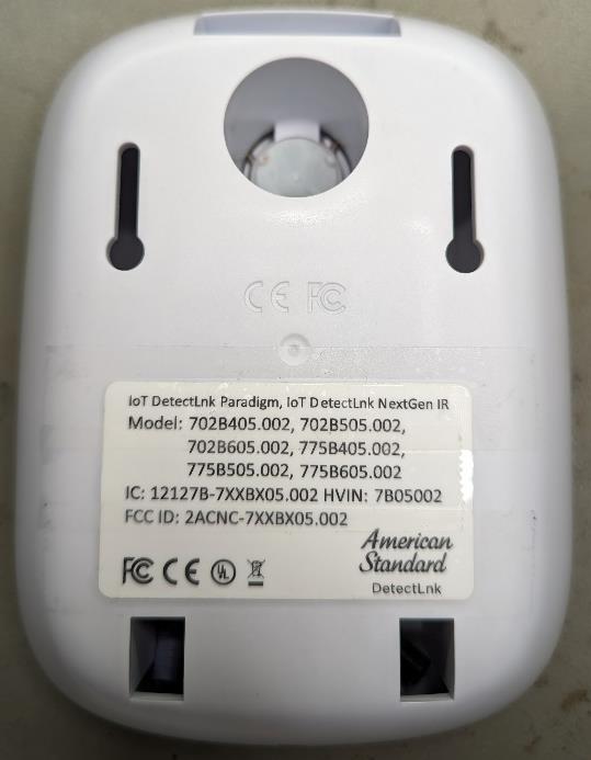
HVIN : 607 : IoT DetectLnk Exposed Toilet Flush valve Label position : Label information : HVIN : 607 : IoT DetectLnk Exposed Toilet Flush valve Label position : Label information: HVIN : 607 : IoT DetectLnk Exposed Urinal Flush valve Label position : Label information: HVIN : 607 : IoT DetectLnk Concealed Urinal Flush valve Label position : Label information:

Internal Photos

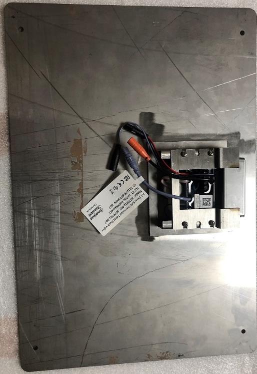
FCC ID : 2ACNC-607XXXX-XXX, Product references : 6072121.002, 607B121.002 Description: IoT DetectLnk Exposed Toilet Flush valve FCC ID : 2ACNC-607XXXX-XXX, Product references : 607B222.007 Description: IoT DetectLnk Concealed Toilet Flush valve FCC ID : 2ACNC-607XXXX-XXX, Product references : 607B322.007 Description: IoT DetectLnk Concealed Toilet Flush valve FCC ID : 2ACNC-607XXXX-XXX, Product references : 6078013.002, 6078051.002, 607B013.002, 607B051.002 Description: IoT DetectLnk Exposed Urinal Flush valve FCC ID : 2ACNC-607XXXX-XXX, Product references : 607B301.007, 607B305.007 Description: IoT DetectLnk Co…

Text truncated - open the document above for the full version.

Contact Information

Applicant

Mark Malatesta(Manager)
[email protected]732-369-4061Fax: 732-980-3100

Technical Contact

AS America, Inc. d/b/a Lixil AmericasStanimir Stoynv
[email protected]908 227 8873

865 Centennial Avenue · Piscataway · United States

Non-Technical Contact

AS America, Inc. d/b/a Lixil AmericasManojkumar Katakdhond
[email protected]732 340 7574

Test Firm

UL International Germany GmbHBernd Woerl
[email protected]004971149002031Fax: -

Technical Specifications

#Rule PartsFrequency RangePower Output
115C2.40 GHz - 2.48 GHz1.10 mW
Confidentiality
Long Term
Grant Notes
Power output is conducted. The antenna(s) used for this transmitter must be installed to provide a separation distance of at least 20cm from all persons and must not be co-located or operated in conjunction with any antenna or transmitter, except in accordance with FCC multi- transmitter product procedures. Users and installers must be provided with antenna installation instructions and transmitter operating conditions for satisfying RF exposure compliance

Other Applications from AS America, Inc. d/b/a Lixil Americas

IOT Sensor for Infrared Faucet - FCC ID 2ACNC-7XXBX05-002 - AS America, Inc. d/b/a Lixil Americas
2ACNC-7XXBX05-002

IOT Sensor for Infrared Faucet

Jul 18, 2023

Equipment Class

DTS - Digital Transmission System