FCCID.CO- FCC ID Database
HomeCompaniesEquipment ClassesSearch

© 2026 FCC ID Database. All rights reserved.

AboutContactData sourced from FCC public records
  1. Home/
  2. AS America, Inc. d/b/a Lixil Americas/
  3. 2ACNC-7XXBX05-002

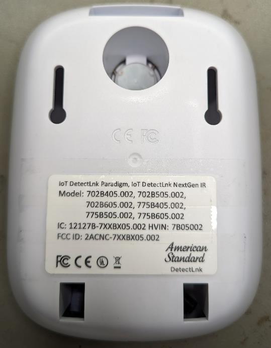
2ACNC-7XXBX05-002IOT Sensor for Infrared Faucet

AS America, Inc. d/b/a Lixil Americas
IOT Sensor for Infrared Faucet - FCC ID 2ACNC-7XXBX05-002 - AS America, Inc. d/b/a Lixil Americas
Click to zoom

Application Details

Equipment Class
DTS - Digital Transmission System
Date of Grant
Jul 18, 2023
Application Purpose
Original Equipment
Date of Application
Jul 18, 2023
Equipment Note
IOT Sensor for Infrared Faucet
Frequency Range
2402.00000000 - 2480.00000000
Company
AS America, Inc. d/b/a Lixil Americas
Country
United States

Documents & Files

Select a file to view
Users Manual

↗
↗

Attestation Statements

↗
↗
↗

Cover Letter(s)

↗
↗

External Photos

↗

ID Label/Location Info

↗

Internal Photos

↗

Operational Description

↗

RF Exposure Info

Test Report

↗
↗

Test Setup Photos

↗

Document Text

Text extracted from the exhibit documents filed with the FCC. Open a document above to read the original.

Users Manual

M985163 EN (7/23) 775B405/775B505/775B605 American Standard is devoted to making life, in the heart of your home, better every day... ...so, thank you for inviting us in! With the very best in kitchen and bathroom products, we are here to help make your life happier, healthier and simpler. Our commitment to quality, innovation and performance has made us part of your everyday routine for nearly 150 years, and we look forward to being a part of your life for many years to come. Learn more at www.AmericanStandard.com REGISTER YOUR WARRANTY Try the easy-scan QR code to quickly enter your information or find your product’s detailed warranty here: www.AmericanStandard.com/warranty Registering allows you to keep your product information safe, and us the ability to contact you in the event of a product recall or any news about your purchase. And if ever you have a question or need help...? Call us at 1-855-815-0004 Plug-In AC Power Kit Hard-Wired AC Power Kit Hard-Wired AC & Multi-AC Power Kit Power Kit PK00.PAC PK00.BBU PK00.WRK PK00.HAC PK00.BBU PK01.MAC / PK00.HAC PK00.BBU POWER KITS SOLD SEPARATELY DO NOT REMOVE PROTECTIVE FILM FROM SENSOR EYE UNTIL INSTALLATION IS COMPLETE. DO NOT REMOVE PROTECTIVE FILM FROM SENSOR EYE UNTIL INSTALLATION IS COMPLETE. OWNERS MANUAL loT Detectlnk ™ NextGen ™ Integrated Faucet with Optional Above-Deck Mixing & SmarTherm ® 775B405 / 775B505 / 775B605 Image shown may vary from product purchased. INSIDE THE BOX RECOMMENDED TOOLS Drill Installation steps will indicate which tools should be used with asscociated letter A 4" and 8" Deck Plate (optional, must be ordered separately) Mounting Kit Spout Assembly (less mixing) Flat Blade Screwdriver B Adjustable Wrench C Spout Assembly (mixing) Assembly Parts Flow SensorFlow Sensor Control Box 775P800 775P400 NOTE TO INSTALLER: Please give this manual to the customer after installation. To learn more about American Standard Selectronic ® Products visit our website at: www.americanstandard-us.com or e-mail us at: [email protected] For Parts, Service, Warranty or other Assistance, please call (844) CRT-TEAM / (844) 278-8326 (In Toronto Area only: 1-905-306-1093) 10 PUTTY (If required) MOUNTING SURFACE (OPTIONAL) TIGHTEN SPIN NUTS 2 1 4 12 13 3 7 8 9 5 I MPORTANT: Do not use putty when installing faucet without escutcheon. IMPORTANT: Do not use sealant on threads 11 1 SPOUT ASSEMBLY INSTALLATION Turn off hot and cold water supplies before beginning. INSTALLATION INSTRUCTIONS A 1. Make sure O-RING (1) is installed in spout base. IMPORTANT: Do not use putty when installing faucet without escutcheon. 2. If installing DECK PLATE (2) (optional): Apply a bead of putty to bottom edge of PUTTY PLATE (2). Install SCREW (11) into the MOUNTING BASE OF THE FAUCET (13) and allign SCREW (11) with HOLE (12). 3. Insert supply HOSES (3), SHANK (4) and WIRES (5) through hole in DECK PLATE with PUTTY PLATE (2) and mounting surface. 4. Assemble RUBBER WASHER (7), BRASS WASHER (8) and THREADED LOCKNUT (9) onto SHANK (4) from underside of sink or mounting surface. Hand tighten LOCKNUT (9). 5. Use a screwdriver to tighten SCREWS (10) on LOCKNUT (9). Work your way around LOCKNUT (9), tightening the screws slightly each time until all are snug to ensure even pressure. 2 MAKE WATER SUPPLY CONNECTIONS B IMPORTANT: Do not use sealent on threads 1 2 3 COLD HOT (3) FLOW SENSOR 5 4 1. Turn off hot and cold water supplies before beginning. 2. Install FLOW SENSOR (3) on each wall supply outlet. Be sure that FLOW SENSOR (3) is inserted in the correct direction. 3. Connect HOT FLEXIBLE SUPPLY (marked with red stripe) (1) to FLOW SENSOR (3) on hot water control stop (4). Connect COLD FLEXIBLE SUPPLY (marked with blue stripe) (2) to FLOW SENSOR (3) on cold water control stop (5). Use adjustable wrench to tighten connections. Do not over tighten. 4. Faucet supplies are 24" long from faucet base. Note: If additional supply length is required, installer must purchase those parts separately. Important; If SUPPLY HOSES (1, 2) are too long, loop as illustrated to avoid kinking. Note: For non-mixing models only one flow sensor and supply line connection is needed. 3 CONTROL BOX INSTALLATION VERTICAL C/L HORIZONTAL C/L 1 2 3 2 3 1. Remove the SCREW (4) from the bottom of the control box and lift the cover off. 2. Determine the mounting location of the control box by checking the wire length of the faucet and flow sensor when connected to the control box. 3. Place the CONTROL BOX (1) on the horizontal center line and mark the location of the mounting holes to be drilled. 4. Using a ¼" diameter drill bit, drill two mounting holes approximately 1" deep. 5. Install the two ANCHORS (2) provided into the mounting holes. 6. Partially thread the SCREWS (3) in to the ANCHORS (2). 7. Place CONTROL BOX (1) over the SCREWS (3) and slide down to lock. 8. Tighten SCREWS (3) if a more secure connection is desired. Note: The cover should be left off as it will be reinstalled at a later point. C 3.1 MAKE WIRED CONNECTIONS 1. Connect IR sensor wire to control box. 2. Connect solenoid wire to control box. 3. Connect flow sensor wires, hot and cold, to the control box. 4. Connect battery wire to the black and purple wire. Note: for non-mixing versions only one flow sensor connection is needed. Internal Wiring External Wiring To IR Sensor To IR Sensor Battery in the Box 2 Pin purple male connector Two wires (black, purple) 2 Pin black wire / black male connector 2 Pin black wire / black female connector To Faucet Solenoid 2 Pin black wire / blue female connector 2 Pin black wire / blue male connector 2 Pin black wire / black female connector 2 Pin black wire / black male connector 3 Pin purple wire / purple female connector 3 Pin purple wire / purple male connector To Flow Sensor 3 Pin purple wire / green female connector 3 Pin purple wire / purple male connector To Flow Sensor AC adapter (if applicable) Note: Green connector can attach to either male purple connector 3.2 AC VERSIONS…

Text truncated - open the document above for the full version.

Users Manual

M985164 EN (7/23) 702B405/702B505/702B605 American Standard is devoted to making life, in the heart of your home, better every day... ...so, thank you for inviting us in! With the very best in kitchen and bathroom products, we are here to help make your life happier, healthier and simpler. Our commitment to quality, innovation and performance has made us part of your everyday routine for nearly 150 years, and we look forward to being a part of your life for many years to come. Learn more at www.AmericanStandard.com REGISTER YOUR WARRANTY Try the easy-scan QR code to quickly enter your information or find your product’s detailed warranty here: www.AmericanStandard.com/warranty Registering allows you to keep your product information safe, and us the ability to contact you in the event of a product recall or any news about your purchase. And if ever you have a question or need help...? Call us at 1-855-815-0004 OWNERS MANUAL loT Detectlnk ™ Paradigm ™ Integrated Faucet with Optional Above-Deck Mixing & SmarTherm ® 702B405 / 702B505 / 702B605 Image shown may vary from product purchased. RECOMMENDED TOOLS Drill Installation steps will indicate which tools should be used with asscociated letter A Flat Blade Screwdriver B Adjustable Wrench C Plug-In AC Power Kit Hard-Wired AC Power Kit Hard-Wired AC & Multi-AC Power Kit PWRX Power Kit PK00.PAC PK00.BBU PK00.WRK PK00.HAC PK00.BBU PK01.MAC / PK00.HAC PK00.BBU POWER KITS SOLD SEPARATELY PROTECTIVE FILM FROM FILM FROM INSTALLATION IS DO NOT REMOVE PROTECTIVE FILM FROM SENSOR EYE UNTIL INSTALLATION IS COMPLETE. DO NOT REMOVE PROTECTIVE FILM FROM SENSOR EYE UNTIL INSTALLATION IS COMPLETE. INSIDE THE BOX 702P.400 Paradigm 4" Mounting Kit Spout Assembly (less mixing) Spout Assembly (mixing) Assembly Parts Flow SensorFlow Sensor Control Box NOTE TO INSTALLER: Please give this manual to the customer after installation. To learn more about American Standard Selectronic ® Products visit our website at: www.americanstandard-us.com or e-mail us at: [email protected] For Parts, Service, Warranty or other Assistance, please call (844) CRT-TEAM / (844) 278-8326 (In Toronto Area only: 1-905-306-1093) 1 SPOUT ASSEMBLY INSTALLATION Turn off hot and cold water supplies before beginning. INSTALLATION INSTRUCTIONS A 1. Make sure O-RING (1) is installed in spout base. IMPORTANT: Do not use putty when installing faucet without escutcheon. 2. If installing DECK PLATE (2) (optional): Apply a bead of putty to bottom edge of PUTTY PLATE (2). Install SCREW (11) into the MOUNTING BASE OF THE FAUCET (13) and allign SCREW (11) with HOLE (12). 3. Insert supply HOSES (3), SHANK (4) and WIRES (5) through hole in DECK PLATE with PUTTY PLATE (2) and mounting surface. 4. Assemble RUBBER WASHER (7), BRASS WASHER (8) and THREADED LOCKNUT (9) onto SHANK (4) from underside of sink or mounting surface. Hand tighten LOCKNUT (9). 5. Use a screwdriver to tighten SCREWS (10) on LOCKNUT (9). Work your way around LOCKNUT (9), tightening the screws slightly each time until all are snug to ensure even pressure. 2 MAKE WATER SUPPLY CONNECTIONS B IMPORTANT: Do not use sealent on threads 1 2 3 COLD HOT (3) FLOW SENSOR 5 4 1. Turn off hot and cold water supplies before beginning. 2. Install FLOW SENSOR (3) on each wall supply outlet. Be sure that FLOW SENSOR (3) is inserted in the correct direction. 3. Connect HOT FLEXIBLE SUPPLY (marked with red stripe) (1) to FLOW SENSOR (3) on hot water control stop (4). Connect COLD FLEXIBLE SUPPLY (marked with blue stripe) (2) to FLOW SENSOR (3) on cold water control stop (5). Use adjustable wrench to tighten connections. Do not over tighten. 4. Faucet supplies are 24" long from faucet base. Note: If additional supply length is required, installer must purchase those parts separately. Important; If SUPPLY HOSES (1, 2) are too long, loop as illustrated to avoid kinking. Note: For non-mixing models only one flow sensor and supply line connection is needed. 10 PUTTY (If required) MOUNTING SURFACE (OPTIONAL) TIGHTEN SPIN NUTS 2 1 4 12 13 3 7 8 9 5 I MPORTANT: Do not use putty when installing faucet without escutcheon. IMPORTANT: Do not use sealant on threads 11 3 CONTROL BOX INSTALLATION VERTICAL C/L HORIZONTAL C/L 1 2 3 2 3 1. Remove the SCREW (4) from the bottom of the control box and lift the cover off. 2. Determine the mounting location of the control box by checking the wire length of the faucet and flow sensor when connected to the control box. 3. Place the CONTROL BOX (1) on the horizontal center line and mark the location of the mounting holes to be drilled. 4. Using a ¼" diameter drill bit, drill two mounting holes approximately 1" deep. 5. Install the two ANCHORS (2) provided into the mounting holes. 6. Partially thread the SCREWS (3) in to the ANCHORS (2). 7. Place CONTROL BOX (1) over the SCREWS (3) and slide down to lock. 8. Tighten SCREWS (3) if a more secure connection is desired. Note: The cover should be left off as it will be reinstalled at a later point. C 3.1 MAKE WIRED CONNECTIONS 1. Connect IR sensor wire to control box. 2. Connect solenoid wire to control box. 3. Connect flow sensor wires, hot and cold, to the control box. 4. Connect battery wire to the black and purple wire. Note: for non-mixing versions only one flow sensor connection is needed. Internal Wiring External Wiring To IR Sensor To IR Sensor Battery in the Box 2 Pin purple male connector Two wires (black, purple) 2 Pin black wire / black male connector 2 Pin black wire / black female connector To Faucet Solenoid 2 Pin black wire / blue female connector 2 Pin black wire / blue male connector 2 Pin black wire / black female connector 2 Pin black wire / black male connector 3 Pin purple wire / purple female connector 3 Pin purple wire / purple male connector To Flow Sensor 3 Pin purple wire / green female connector 3 Pin purple wire / purple male connector To Flow Sensor AC adapter (if applicable) Note: Green connector can attach to either male purple connector 3.2 AC VERSIONS (…

Text truncated - open the document above for the full version.

Attestation Statements

CFR 47 §2.911 (d)(5) Attestation Date: 05-16-2023 FCC ID: 2ACNC-7XXBX05-002 To: Federal Communications Commission 7435 Oakland Mills Road Columbia, MD 21046 USA 1. AS America, Inc. d/b/a LIXIL Americas (“the applicant”) certifies that the equipment for which authorization is sought is not “covered” equipment prohibited from receiving an equipment authorization pursuant to section 2.903 of the FCC rules. 2. AS America, Inc. d/b/a LIXIL Americas (“the applicant”) certifies that, as of the date of the filing of the application, the applicant is not identified on the Covered List as an entity producing “covered” equipment and is not an affiliate or subsidiary of an entity identified on the Covered List. Sincerely yours, Mark Malatesta Name: Mark Malatesta Job Title: Manager Company Name: AS America, Inc. d/b/a LIXIL Americas

Attestation Statements

CFR 47 §2.911 (d)(7) FCC US Agent Letter of Attestation Date: 05-16-2023 FCC ID: 2ACNC-7XXBX05-002 To: Federal Communications Commission 7435 Oakland Mills Road Columbia, MD 21046 USA FCC US Agent AS America, Inc. d/b/a LIXIL Americas FRN: 0023746563 Mark Malatesta 30 Knightsbridge Road, Suite 30 Piscataway, NJ 08854 [email protected] This letter is to confirm that we have accepted the responsibility to act as US Agent on behalf of AS America, Inc. d/b/a LIXIL Americas (“the applicant”) for the above referenced FCC ID. We are aware of the requirements and responsibilities of the applicant’s agent for service of process as outlined in the FCC section 2.911(d)(7) and Report and Order FCC 22-84 paragraph 63. Sincerely yours, Mark Malatesta Mark Malatesta Manager AS America, Inc. d/b/a LIXIL Americas

Attestation Statements

CFR 47 §2.911 (d)(7) Agent Designation Attestation Date: 05-16-2023 FCC ID: 2ACNC-7XXBX05-002 To: Federal Communications Commission 7435 Oakland Mills Road Columbia, MD 21046 USA AS America, Inc. d/b/a LIXIL Americas (“the applicant”) as required by section 2.911(d)(7), designates the following agent, located in the United States, for purposes of acting as the applicant’s agent for service of process. The applicant acknowledges that they will maintain an agent for no less than one year after the grantee has terminated all marketing and importation or the conclusion of any Commission-related proceeding involving the equipment. The applicant further acknowledges their responsibility to inform the FCC whenever the agent information changes. U. S. Agent Information: Mark Malatesta AS America, Inc. d/b/a LIXIL Americas 30 Knightsbridge Road, Suite 30 Piscataway, NJ 08854 [email protected] Sincerely yours, Mark Malatesta Name: Mark Malatesta Job Title: Manager Company Name: AS America, Inc. d/b/a LIXIL Americas

Cover Letter(s)

07/04/2022 Telecommunication Certification Body UL International (UK) Ltd. Units 1-3, Horizon Wade Road Kingsland Business Park Basingstoke Hampshire RG24 8AH United Kingdom Subject: Authorisation Letter To whom it may concern This is to certify that AS America, Inc. d/b/a LIXIL Americas hereby authorises UL International (UK) Ltd. to act as the TCB for the application of the 702B405.002, 702B505.002, 702B605.002, 775B405.002, 775B505.002, 775B605.002, FCC ID: 2ACNC-7XXBX05-002 to the FCC. We certify that we are not subject to a denial of Federal benefits, that include FCC benefits, pursuant to Section 5301 of the Anti-Drug Abuse Act of 1988, 21 U.S.C. § 862 because of a conviction for possession or distribution of a controlled substance. See 47 CFR 1.2002(b) for the definition of a "party" for these purposes. Yours faithfully, Mark Malatesta Mark Malatesta Manager

Cover Letter(s)

07/04/2022 Telecommunication Certification Body UL International (UK) Ltd. Units 1-3, Horizon Wade Road Kingsland Business Park Basingstoke Hampshire RG24 8AH United Kingdom Subject: Permanent Confidentiality Request Certification Application FCC ID: 2ACNC-7XXBX05-002 To whom it may concern Pursuant to Sections 0.457(d) and 0.459 of CFR 47, AS America, Inc. d/b/a LIXIL Americas request that the following information, provided to support the FCC application for the 702B405.002, 702B505.002, 702B605.002, 775B405.002, 775B505.002, 775B605.002, FCC ID: 2ACNC-7XXBX05-002 be held permanently confidential: Schematics Block Diagrams Parts List Operational Description The above material contains trade secrets not customarily released to public that are judged to have the potential to cause detriment to the applicant and provide unjustified benefits to its competitors. This information should not be available for public disclosure for an indefinite period of time. Yours faithfully Mark Malatesta Manager Mark Malatesta

External Photos

FCC ID : 2ACNC-7XXBX05-002, Product references : 702B405.002, 702B505.002, 702B605.002, 775B405.002, 775B505.002, 775B605.002 Description: IOT sensor for Infrared Faucet Top view Right view Front view Left view Back view Bottom view

ID Label/Location Info

HVIN : 7B05002 : IoT DetectLnk IR Faucet Label position : Label information:

Internal Photos

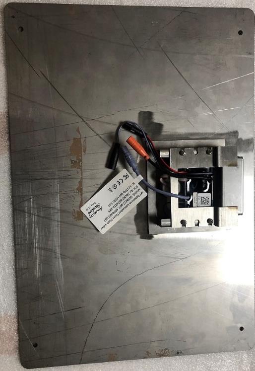
FCC ID : 2ACNC-7XXBX05-002, Product references : 702B405.002, 702B505.002, 702B605.002, 775B405.002, 775B505.002, 775B605.002 Description: IOT sensor for Infrared Faucet

Operational Description

nRF52840 SoC Product Brief Version 3.0 For more information please visit: nordicsemi.com/nRF52840 Key features  64 MHz Arm® Cortex-M4 with FPU  1 MB Flash + 256 KB RAM  Bluetooth 5.3 multiprotocol radio y2 Mbps yCSA #2 yAdvertising Extensions yLong Range y+8 dBm TX power y-95 dBm sensitivity yIntegrated balun with 50 Ω single- ended output  IEEE 802.15.4 radio support yThread yZigbee  1.7-5.5 V supply voltage range  Full-speed 12 Mbps USB  NFC-A tag  Arm CryptoCell CC310 security subsystem  QSPI/SPI/TWI/I²S/PDM/QDEC  High speed 32 MHz SPI  Quad SPI interface 32 MHz  EasyDMA for all digital interfaces  12-bit 200 ksps ADC  128 bit AES/ECB/CCM/AAR co-processor  On-chip DC-DC buck converter  Regulated supply for external components up to 25 mA Applications  IoT ySmart Home products yMatter connected home products yIndustrial mesh networks ySmart city infrastructure  Advanced wearables yConnected watches yAdvanced personal fitness devices yWearables with wireless payment yConnected Health yVirtual/Augmented Reality applications  Interactive entertainment devices yAdvanced remote controls yGaming controller Ready for Bluetooth 5.3 and high grade IoT security The nRF52840 is an advanced, highly flexible single chip solution for today’s increasingly demanding ULP wireless applications for connected devices on our person, connected living environments and the IoT at large. It is designed ready for the major feature advancements of Bluetooth LE and takes advantage of increased performance capabilities which include long range and high throughput modes. Inherent industry-grade security is essential in today’s applications. The nRF52840 adds best-in-class security for Cortex TM -M Series with on-chip ARM ® CryptoCell cryptographic accelerator. nRF52840 High-end multiprotocol Bluetooth Low Energy (LE) SoC supporting: Bluetooth 5.3/Bluetooth mesh/Thread/ Zigbee/802.15.4/ANT Advanced performance, lowest power consumption The nRF52840 employs the same hardware and software architecture as existing nRF52 Series SoCs. At its core is an Arm Cortex-M4 processor allowing quicker and more efficient computation of complex functions for DSP and those requiring floating point math. There is extensive memory availability in both flash and RAM, 1 MB and 256 KB respectively. The combination of Cortex-M4 with floating point and memory availability offers unparalleled capabilities for true single chip applications. A full-speed (12 Mbps) USB 2.0 controller is included on-chip. An extensive range of peripherals are available with a number of high performance digital interfaces such as high speed SPI (32 MHz) and quad SPI (32 MHz) to allow direct interfacing to displays and external memory sources. The nRF52840 can operate from +5.5 V down to 1.7 V supply voltages allowing direct supply from rechargeable batteries and USB supplies. nRF52805nRF52810nRF52811nRF52820nRF52832nRF52833nRF52840nRF5340 Bluetooth 5.3 XXXXXXXX Bluetooth 2 Mpbs XXXXXXXX Bluetooth Long Range XXXXX Bluetooth Direction Finding XXXX Bluetooth LE Audio X Bluetooth mesh XXXXX Thread XXXXX Zigbee XXXX Matter XX nRF5340 SoC Product Brief Version 3.0 For more information please visit: nordicsemi.com/nRF52840 Specifications Related Products Protocol supportBluetooth 5.3/802.15.4/ANT/2.4 GHz proprietary Microprocessor64 MHz 32-bit Arm Cortex-M4 with FPU Memory1 MB Flash + 256 KB RAM On-air data rateBluetooth LE: 2 Mbps/1 Mbps/500 kbps/125 kbps 802.15.4: 250 kbps 2.4 GHz proprietary: 2 Mbps/ 1 Mbps TX powerProgrammable from +8 dBm to -20 dBm in 4 dB steps SensitivityBluetooth LE: -103 dBm at 125 kbps -95 dBm at 1 Mbps 802.15.4: -100 dBm at 250 kbps 2.4 GHz: -93 dBm at 1 Mbps -89 dBm at 2 Mbps Radio current consumption DC/DC at 3 V 16.40 mA at +8 dBm TX power, 6.40 mA at 0 dBm TX power, 6.26 mA in RX at 1 Mbps Oscillators64 MHz from 32 MHz external crystal or internal 32 kHz from crystal, RC or synthe- sized System current consumption DC/DC at 3 V 0.4 μA in System OFF, no RAM retention 1.86 μA in System OFF, full RAM retention 0.97 μA in System ON, no RAM retention 2.35 μA in System ON, full RAM retention 3.16 μA in System ON, full RAM retention and RTC Hardware security 128-bit AES CCM, ECB, AAR Security subsys- tem Arm TrustZone CryptoCell 310 Digital interfacesUSB 2.0, 4 x SPI master/slave, 2 x TWI mas- ter/slave, 2 x UART, 4 x PWM, QPSI, I²S, PDM, QDEC Analog interfaces12-bit 200 ksps ADC, GP comparator, LP comparator Peripherals5 x 32 bit timer/counter, 3 x 24 real-time counter, 20 x PPI channels, 4 x GPIOTE, temperature sensor, watchdog timer, RNG NFCNFC-A tag Voltage supply1.7 to 5.5 V LDO or DC/DC Package options7 x 7 aQFN73 with 48 GPIOs 6 x 6 QFN48 with 30 GPIOs 3.5 x 3.6 WLCSP94 with 48 GPIOs nRF52840 DKDevelopment kit for nRF52811 and nRF52840 SoCs nRF Connect SDKMain software development kit for the nRF 52840 SoC and other nRF52 Series SoCs Power Profiler Kit IIHardware tool for current measurement and power profiling your applications nRF21540 RF FEMRange extender front end for Bluetooth LE, Thread and Zigbee applications nPM1100 PMICHigly efficient power management IC for low power small form factor devices Thread certified and 802.15.4 support The nRF52840 is a Thread certified component and as such is ideal for home networking products using the Thread mesh stack. This means it is suitable for developing products for the Matter connected home ecosystem. The radio supports 802.15.4 PHY and MAC layers and makes it suitable for additional stacks using 802.15.4 such as Zigbee. Arm CryptoCell 310 The nRF52840 features an on-chip Arm CryptoCell 310 cryptographic hardware accelerator. CryptoCell offers a wide range of ciphers and security features for building solid security into applications from the ground up. Use of CryptoCell also makes associated security operations run faster and uses less processing time and power than equivalent operation carried out in software by the CPU. nRF Connect SDK The nRF Connect SDK is the softw…

Text truncated - open the document above for the full version.

Test Report

UL INTERNATIONAL GERMANY GMBH Hedelfinger Str. 61 70327 Stuttgart, Germany [email protected] TEST REPORT Test Report No.: UL-RPT-RP-14296454-1216-FCC Applicant : AS America, Inc. d/b/a LIXIL Americas Model No. : NextGen IR faucet FCC ID : 2ACNC-7XXBX05-002 Technology : Bluetooth – Low Energy Test Standard(s) : FCC Parts 15.207, 15.209(a) & 15.247 For details of applied tests refer to test result summary 1. This test report shall not be reproduced in full or partial, without the written approval of UL International Germany GmbH. 2. The results in this report apply only to the sample tested. 3. The test results in this report are traceable to the national or international standards. 4. Test Report Version 1.2 supersede Version 1.1 with immediate effect Test Report No. UL-RPT-RP-14296454-1216-FCC Version 1.2, Issue Date 24 OCTOBER 2022 replaces Test Report No. UL-RPT-RP-14296454-1216-FCC Version 1.1, Issue Date 04 OCTOBER 2022, which is no longer valid. 5 Result of the tested sample: PASS ______________________________ ____________________________ Prepared by: Muhammad Faiq Khan Approved by: Rachid, Acharkaoui Title: Project Engineer Title: Operations Manager Date: 24 October 2022 Date: 24 October 2022 This laboratory is accredited by DAkkS. The tests reported herein have been performed in accordance with its’ terms of accreditation. UL INTERNATIONAL GERMANY GMBH TEST REPORT NO: UL-RPT-RP-14296454-1216-FCC TEST REPORT VERSION 1.2 ISSUE DATE: 24 OCTOBER 2022 Page 2 of 51 FCC 15.247 BT LE - Template Vers. 1.4 This page has been left intentionally blank. UL INTERNATIONAL GERMANY GMBH TEST REPORT NO: UL-RPT-RP-14296454-1216-FCC TEST REPORT VERSION 1.2 ISSUE DATE: 24 OCTOBER 2022 Page 3 of 51 FCC 15.247 BT LE - Template Vers. 1.4 Table of Contents 1. Customer Information .............................................................................................................. 4 1.1. Applicant Information 4 1.2. Manufacturer Information 4 2. Summary of Testing ................................................................................................................. 5 2.1. General Information 5 Applied FCC Rule Part(s) 5 Location 5 Date Information 5 2.2. Summary of Test Results 6 2.3. Methods and Procedures 6 2.4. Deviations from the Test Specification 6 3. Equipment Under Test (EUT) .................................................................................................. 7 3.1. Identification of Equipment Under Test (EUT) 7 3.2. Description of EUT 7 3.3. Modifications Incorporated in the EUT 7 3.4. Additional Information Related to Testing 8 3.5. Support Equipment 9 A. Support Equipment (In-house) 9 B. Support Equipment (Manufacturer supplied) 9 4. Operation and Monitoring of the EUT during Testing ......................................................... 10 4.1. Operating Modes 10 4.2. Configuration and Peripherals 11 5. Measurements, Examinations and Derived Results ............................................................ 12 5.1. General Comments 12 5.2. Test Results 13 5.2.1. Transmitter AC Conducted Spurious Emissions 13 5.2.2. Transmitter Duty Cycle 18 5.2.3. Transmitter 6 dB Bandwidth 23 5.2.4. Transmitter Maximum Peak Output Power 28 5.2.5. Transmitter Radiated Emissions 34 Transmitter Radiated Emissions (continued) 37 Transmitter Radiated Emissions (continued) 39 5.2.6. Transmitter Band Edge Radiated Emissions 43 6. Measurement Uncertainty ..................................................................................................... 49 7. Used equipment ..................................................................................................................... 50 8. Report Revision History ........................................................................................................ 51 UL INTERNATIONAL GERMANY GMBH TEST REPORT NO: UL-RPT-RP-14296454-1216-FCC TEST REPORT VERSION 1.2 ISSUE DATE: 24 OCTOBER 2022 Page 4 of 51 FCC 15.247 BT LE - Template Vers. 1.4 1. Customer Information 1.1. Applicant Information Company Name: AS America, Inc. d/b/a LIXIL Americas Company Address: 30 Knightsbridge Road Piscataway, NJ 08854, USA Company Phone No.: + 1 855-815-0004 Contact Person: Mr. Mark Malatesta Contact E-Mail Address: [email protected] Contact Phone No.: +1 762-369-4061 1.2. Manufacturer Information Company Name: AS America, Inc. d/b/a LIXIL Americas Company Address: 30 Knightsbridge Road Piscataway, NJ 08854, USA Company Phone No.: + 1 855-815-0004 Contact Person: Mr. Stanimir Soynov Contact E-Mail Address: [email protected] Contact Phone No.: +1 908 227 8873 UL INTERNATIONAL GERMANY GMBH TEST REPORT NO: UL-RPT-RP-14296454-1216-FCC TEST REPORT VERSION 1.2 ISSUE DATE: 24 OCTOBER 2022 Page 5 of 51 FCC 15.247 BT LE - Template Vers. 1.4 2. Summary of Testing 2.1. General Information Applied FCC Rule Part(s) Specification Reference: 47CFR15.247 Specification Title: Code of Federal Regulations Volume 47 (Telecommunications): Part 15 Subpart C (Intentional Radiators) - Section 15.247 Specification Reference: 47CFR15.207 and 47CFR15.209 Specification Title: Code of Federal Regulations Volume 47 (Telecommunications): Part 15 Subpart C (Intentional Radiators) - Sections 15.207 and 15.209 Location Location of Testing: UL International Germany GmbH Hedelfinger Strasse. 61, 70327 Stuttgart, GERMANY Registration Number: 399704 Date Information Order Date: 20 April 2022 EUT Arrived: 11 July 2022 Test Dates: 22 July 2022 to 22 September 2022 EUT Returned: -/- UL INTERNATIONAL GERMANY GMBH TEST REPORT NO: UL-RPT-RP-14296454-1216-FCC TEST REPORT VERSION 1.2 ISSUE DATE: 24 OCTOBER 2022 Page 6 of 51 FCC 15.247 BT LE - Template Vers. 1.4 2.2. Summary of Test Results DIGITAL TRANSMISSION SYSTEMS (DTS): 2400-2483.5 MHz FCC Part 15 Clause Compliance Test Description Test Result C N.C. N.P. N.A. 15.207 Transmitter AC Power Line Conducted Emissions ☒ ☐ ☐ ☐ 15.35(c) Transmitter Duty Cycle (1) ☒ ☐ ☐ ☐ 15.247(a)(2) Transmitter Minimum 6 dB Ba…

Text truncated - open the document above for the full version.

Test Report

2.4 GHz FlexPIFA Antenna, 100mm Datasheet The information in this document is subject to change without notice. 330-0149-R3.4 Copyright © 2014-2017 LSR Page 1 of 31 2.4 GHz – 2.5 GHz FlexPIFA 2 dBi Antenna w/U.FL Cable, 100mm ORDERING INFORMATION Order Number Description 001-0014 2.4 GHz FlexPIFA Antenna w/U.FL Cable, 100mm 001-0022 2.4 GHz FlexPIFA Antenna w/MHF4L Cable, 100mm 001-0025 2.4 GHz FlexPIFA Antenna w/U.FL Cable, 100mm, LH Table 1 Orderable Part Numbers KEY FEATURES ▪ Can be installed on different non- conductive surfaces and thicknesses. ▪ Can be installed near metals or the human body. ▪ Can be installed on flat or curved surfaces. ▪ Quick and easy Installation ▪ Adhesive holds to surface during humidity exposure and hot/cold cycles. ▪ RoHS Compliant 2.4 GHz FlexPIFA Antenna, 100mm Datasheet The information in this document is subject to change without notice. 330-0149-R3.4 Copyright © 2014-2017 LSR Page 2 of…

Text truncated - open the document above for the full version.

Contact Information

Applicant

Mark Malatesta(Manager)
[email protected]732-369-4061Fax: 732-980-3100

Technical Contact

AS America, Inc. d/b/a Lixil AmericasStanimir Stoynv
[email protected]908 227 8873

865 Centennial Avenue · Piscataway · United States

Non-Technical Contact

AS America, Inc. d/b/a Lixil AmericasManojkumar Katakdhond
[email protected]9082278873

Test Firm

UL International Germany GmbHBernd Woerl
[email protected]004971149002031Fax: -

Technical Specifications

#Rule PartsFrequency RangePower Output
115C2.40 GHz - 2.48 GHz1.10 mW
Confidentiality
Long Term
Grant Notes
Power output is conducted. The antenna(s) used for this transmitter must be installed to provide a separation distance of at least 20cm from all persons and must not be co-located or operated in conjunction with any antenna or transmitter, except in accordance with FCC multi- transmitter product procedures. Users and installers must be provided with antenna installation instructions and transmitter operating conditions for satisfying RF exposure compliance.

Other Applications from AS America, Inc. d/b/a Lixil Americas

IOT Sensor for Urinals and Toilet - FCC ID 2ACNC-607XXXX-XXX - AS America, Inc. d/b/a Lixil Americas
2ACNC-607XXXX-XXX

IOT Sensor for Urinals and Toilet

Jul 18, 2023

Equipment Class

DTS - Digital Transmission System