2ACOA-ID2IoT gateway
Zenner USA, Inc.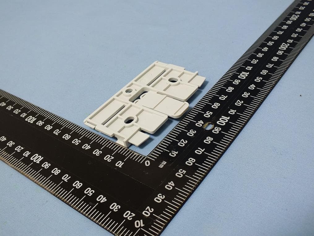
Click to zoom
Application Details
- Equipment Class
- DTS - Digital Transmission System
- Date of Grant
- Mar 14, 2021
- Application Purpose
- Original Equipment
- Date of Application
- Mar 11, 2021
- Equipment Note
- IoT gateway
- Frequency Range
- 923.30000000 - 927.50000000
- Company
- Zenner USA, Inc.
- Country
- United States
Documents & Files
Document Text
Text extracted from the exhibit documents filed with the FCC. Open a document above to read the original.
Users Manual
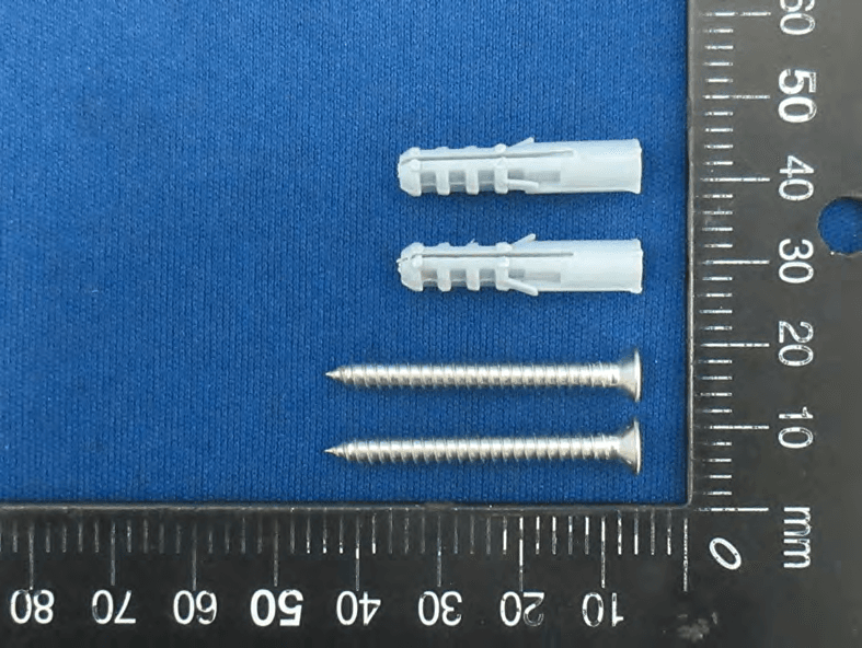
English Installation instructions IoT gateway indoor 1. General information 3. Installation location In order to gain optimum LoRaWAN network coverage, an installation location which is as high as possible is recommended due to various technological advan- tages. For example, if an attic is available with potential installation space, this installation location should be preferred. Note: In stairwells and hallways, the current building regulations should be checked. It is not permitted to install the product in the service room of the lift. After selecting the preferred installation location, you should test the mobile radio connection in this location prior to attaching it. 1.1. Intended use Operational safety is only guaranteed if the product is used as intended by the manufacturer. No liability is assumed for damage caused by other applications. Any modifications are only permitted with approval from the manufacturer. Otherwise the manufacturer’s declaration is invalidated. 1.2. Safety instructions If it is necessary to establish a new power connec- tion, the installation and commissioning must only be performed by trained qualified specialists. Only trained qualified electricians may work on electrical systems. They must be able to assess the work assigned to them at all times, detect any potential sources of danger and adopt appropriate safety measures. The installation work must only be performed in a de-energised state. Valid specifications and standards are to be observed. 4. Installation 4.1. Check whether cables are routed to the selected installation point. Note the length of the power cable (range for socket / junction box). Mark drilling holes on the wall according to the hole spacing and use a spirit level (drilling template attached) (ill. 1). Drill drilling holes, fit dowels and screws in the holes (included in scope of delivery). Attach wall mounting bracket to the wall. Ensure that the correct side of the wall moun- ting bracket faces upwards. Pay attention to the following illustration (ill. 1). Tip: In the case of uneven walls, use washers. 4.2. 4.3. 2. Product description 4.4. 2.1. Intended use The ZENNER IoT Gateways use high-performance Lo- RaWAN® technology, whose excellent building penetra- tion and long-range network coverage generally ensure the connectivity of IoT sensors even under challenging environmental and installation conditions. The Indoor Gateway is ideally suited for LoRa network coverage within a building to receive the values of sensors, some of which are difficult to access, on several floors and in basements - without the need for additional repeaters. The device can be used across various sectors for a variety of IoT applications and is an integral part of ZENNER IoT system solutions. 4.5. ⬆ 2.2. Scope of delivery ZENNER IoT Indoor Gateway incl. integrated SIM Mounting hardware (screws & dowels) Installation and operating instructions Declaration of conformity ill. 1 ■ 4.6. Snap the gateway into the wall mounting bracket. The electrical connection is then established. ■ ■ ■ ⬆ 5 ill. 2 5. Electrical connection 6. Commissioning Gateway with plug-in power supply The gateway starts immediately after insertion / con- nection. The gateway passes through several phases during the boot process, which are indicated by the LEDs. Please observe the following sequence of the four LEDs. LED No. 4 signals the connection to the backend. ■ This variant is operated with a plug-in power sup- ply. The electrical connection can be established by a laymen. Commissioning is performed by inserting the power supply unit. ill. 3 1. Off Off Off Off Boot process 3. Green Off Red Red Gateway with plug-in power supply 5. Green Off Off Red Ready for opera- tion - network con- 6.2 nection Green / Orange Green Red Green Flashes red / Off green A. Off Green Flashes red / Off green Red Red Explanation of the stages: 1. 2. 3. 4. No power supply Hardware initialisation Hardware initialisation Mobile radio connection not active, no connection to LoRa network server (LNS) Mobile radio connection active, no connection to LNS Normal operation (6.2, 6.3) 5. 6. ill. 4 6 Update via 6.4 network Flashes red / Green / Red Green green Orange Ready for opera- tion - network connection 6.3 Green Green / Off Green Orange reserved 6.1 Green Off Off Green 4. Green Off Red Red 2. Red Red Off Off Phase Stage 1 2 3 4 reserved reserved 6.5 English 7. Technical data and performance characteristics Suitable for LoRaWAN® IoT solutions from ZENNER Plug & Play - Simple integration into the ZENNER system landscape through pre-configured software* Compatible with the Gateway Management System (GMS) from ZENNER (remote configuration)* Security patches and software updates are distributed in an automated manner* ■ ■ ■ ■ N/A Mobile radio 8 channels internal antenna # LoRa channel US-902 Frequency Internal LoRa antenna Antennas Plastic with flame retardancy according to UL94-2013 edition 9-2019, class.: V-0 Housing -40°C to +80°C Storage temperature Wall (bracket incl. screws and dowels included in scope of delivery) Installation Gateway with plug-in power supply: Width mm 127 Weight approx. kg 0.474 Dimensions of gateway with plug-in power supply * ZENNER IoT Gateways (Indoor and Outdoor) are only compatible as standard with the ZENNER system landscape or ZE- NNER LoRa network server (LNS) by means of Plug’n’Play. The gateways are automatically detected in the backend and can subsequently be monitored and configured by the integrated Gateway Management System (GMS). Software updates and security patches are also distributed in an automated manner. Network operation is performed by Minol ZENNER Connect GmbH. 7 Height mm 48 Length mm 184 Dimensions and weights: Maintenance Remote firmware upgrades LED Power, LAN, reserved, backend connection Operating temperature 0°C to +50°C Protection class IP40 Power supply External power supply unit (230 V) TX power max. 27 dBm (500 mW) conducted LAN RJ45 Technical data 8. D…
Text truncated - open the document above for the full version.
External Photos
Project No.: EP080603 Page No. : 1 of 35 Photographs of EUT Model: 915id PoE Project No.: EP080603 Page No. : 2 of 35 Project No.: EP080603 Page No. : 3 of 35 Project No.: EP080603 Page No. : 4 of 35 Project No.: EP080603 Page No. : 5 of 35 Project No.: EP080603 Page No. : 6 of 35 Project No.: EP080603 Page No. : 7 of 35 Project No.: EP080603 Page No. : 8 of 35 Project No.: EP080603 Page No. : 9 of 35 Project No.: EP080603 Page No. : 10 of 35 Project No.: EP080603 Page No. : 11 of 35 Model: 915id Project No.: EP080603 Page No. : 12 of 35 Project No.: EP080603 Page No. : 13 of 35 Project No.: EP080603 Page No. : 14 of 35 Project No.: EP080603 Page No. : 15 of 35 Project No.: EP080603 Page No. : 16 of 35 Project No.: EP080603 Page No. : 17 of 35 Project No.: EP080603 Page No. : 18 of 35 Project No.: EP080603 Page No. : 19 of 35
ID Label/Location Info
ZENNER IoT gateway, model 915id S/N: 04B64830007F made in China power input: 12V 2A FCC ID: 2ACOA-ID2 SAP: 16xxxx ZENNER IoT gateway, model 915id PoE made in China power input: 12V 2A FCC ID: 2ACOA-ID2 S/N: 04B64830007F SAP: 16xxxx PMN: IoT gateway HVIN: 915id FVIN: 2.0 IC: 26631-ID2 PMN: IoT gateway HVIN: 915id PoE FVIN: 2.0 IC: 26631-ID2 This device complies with Part 15 of the FCC Rules. Operation is subject to the following two conditions: (1) this device may not cause harmful interference, and (2) this device must accept any interference received, including interference that may cause undesired operation. FCC ID: 2ACOA-ID2 This device complies with Part 15 of the FCC Rules. Operation is subject to the following two conditions: (1) this device may not cause harmful interference, and (2) this device must accept any interference received, including interference that may cause undesired operation. FCC ID: 2ACOA-ID2 FCC ID: 2ACOA-ID2 IC: 26631-ID2
Internal Photos
Project No.: EP080603 Page No. : 20 of 35 Model: 915id PoE Project No.: EP080603 Page No. : 21 of 35 Project No.: EP080603 Page No. : 22 of 35 Project No.: EP080603 Page No. : 23 of 35 Project No.: EP080603 Page No. : 24 of 35 Project No.: EP080603 Page No. : 25 of 35 Project No.: EP080603 Page No. : 26 of 35 Project No.: EP080603 Page No. : 27 of 35 Project No.: EP080603 Page No. : 28 of 35 Model: 915id Project No.: EP080603 Page No. : 29 of 35 Project No.: EP080603 Page No. : 30 of 35 Project No.: EP080603 Page No. : 31 of 35 Project No.: EP080603 Page No. : 32 of 35 Project No.: EP080603 Page No. : 33 of 35 Project No.: EP080603 Page No. : 34 of 35 Project No.: EP080603 Page No. : 35 of 35
RF Exposure Info
Report No.: FA080603 Page : 1 of 6 Report Version: Rev. 01 FCC RF Exposure Report FCC ID : 2ACOA-ID2 Equipment : IoT gateway Model No. : 915id PoE ; 915id Brand Name : ZENNER USA Applicant : Zenner USA, Inc. Address : 15280 Addison Rd., Suite 240, Addison, TX 75001 Standard : 47 CFR FCC Part 2.1091 Received Date : Dec. 08, 2020 Tested Date : Dec. 11, 2020 ~ Jan. 26, 2021 We, International Certification Corp., would like to declare that the tested sample has been evaluated and in compliance with the requirement of the above standards. The test results contained in this report refer exclusively to the product. It may be duplicated completely for legal use with the approval of the applicant. It shall not be reproduced except in full without the written approval of our laboratory. Reviewed by: Approved by: Along Chen / Assistant Manager Gary Chang / Manager Report No.: FA080603 Page : 2 of 6 Report Version: Rev. 01 Table of Contents 1 MPE EVALUATION OF MOBILE DEVICES ......................................................................................... 4 1.1 LIMITS FOR GENERAL POPULATION/UNCONTROLLED EXPOSURE............................................. 4 1.2 MPE EVALUATION FORMULA ............................................................................................................. 4 1.3 DEVIATION FROM TEST STANDARD AND MEASUREMENT PROCEDURE ................................... 4 1.4 MEASUREMENT UNCERTAINTY ......................................................................................................... 4 1.5 MPE EVALUATION RESULTS .............................................................................................................. 5 2 TEST LABORATORY INFORMATION ................................................................................................. 6 Report No.: FA080603 Page : 3 of 6 Report Version: Rev. 01 Release Record Report No. Version Description Issued Date FA080603 Rev. 01 Initial issue Mar. 05, 2021 Report No.: FA080603 Page : 4 of 6 Report Version: Rev. 01 1 MPE EVALUATION OF MOBILE DEVICES 1.1 LIMITS FOR GENERAL POPULATION/UNCONTROLLED EXPOSURE Frequency Range (MHz) Power Density (mW /cm 2 ) Averaging Time (minutes) 300~1500 F/1500 30 1500~100000 1.0 30 1.2 MPE EVALUATION FORMULA Pd = 2 **4RPi Pt Where Pd= Power density in mW/cm 2 Pt= EIRP in mW Pi= 3.1416 R= Measurement distance 1.3 DEVIATION FROM TEST STANDARD AND MEASUREMENT PROCEDURE None 1.4 MEASUREMENT UNCERTAINTY The measurement uncertainties given below are based on a 95% confidence level (based on a coverage factor (k=2)). Parameters Uncertainty Conducted power ±0.808 dB Declaration of Conformity: The test results with all measurement uncertainty excluded are presented in accordance with the regulation limits or requirements declared by manufacturers. Comments and Explanations: The declared of product specification for EUT presented in the report are provided by the manufacturer, and the manufacturer takes all the responsibilities for the accuracy of product specification. Report No.: FA080603 Page : 5 of 6 Report Version: Rev. 01 1.5 MPE EVALUATION RESULTS Frequency (MHz) Maximum Conducted Power (dBm) Rated Power (dBm) Antenna Gain (dBi) Distance (cm) Power Density (mW/cm 2 ) Limit (mW/cm 2 ) *Ratio Pass / Fail 923.3 ~ 927.5 26.99 27 1.7 20 0.147 0.616 0.240 Pass *Ratio = Power density / Limit Report No.: FA080603 Page : 6 of 6 Report Version: Rev. 01 2 Test laboratory information Established in 2012, ICC provides foremost EMC & RF Testing and advisory consultation services by our skilled engineers and technicians. Our services employ a wide variety of advanced edge test equipment and one of the widest certification extents in the business. International Certification Corp (EMC and Wireless Communication Laboratory), it is our definitive objective is to institute long term, trust-based associations with our clients. The expectation we set up with our clients is based on outstanding service, practical expertise and devotion to a certified value structure. Our passion is to grant our clients with best EMC / RF services by oriented knowledgeable and accommodating staff. Our Test sites are located at Linkou District and Kwei Shan District. Location map can be found on our website http://www.icertifi.com.tw. Linkou Kwei Shan Kwei Shan Site II Tel: 886-2-2601-1640 Tel: 886-3-271-8666 Tel: 886-3-271-8640 No. 30-2, Ding Fwu Tsuen, Lin Kou District, New Taipei City, Taiwan, R.O.C. No. 3-1, Lane 6, Wen San 3rd St., Kwei Shan District, Tao Yuan City 333, Taiwan, R.O.C. No. 14-1, Lane 19, Wen San 3rd St., Kwei Shan District, Tao Yuan City 333, Taiwan, R.O.C.. If you have any suggestion, please feel free to contact us as below information Tel: 886-3-271-8666 Fax: 886-3-318-0155 Email: [email protected] ══END══
Test Report
Report No.: FR080603 Page : 1 of 51 Report Version: Rev. 01 FCC Test Report FCC ID : 2ACOA-ID2 Equipment : IoT gateway Model No. : 915id PoE ; 915id Brand Name : ZENNER USA Applicant : Zenner USA, Inc. Address : 15280 Addison Rd., Suite 240, Addison, TX 75001 Standard : 47 CFR FCC Part 15.247 Received Date : Dec. 08, 2020 Tested Date : Dec. 11, 2020 ~ Jan. 26, 2021 We, International Certification Corp., would like to declare that the tested sample has been evaluated and in compliance with the requirement of the above standards. The test results contained in this report refer exclusively to the product. It may be duplicated completely for legal use with the approval of the applicant. It shall not be reproduced except in full without the written approval of our laboratory. Reviewed by: Approved by: Along Chen / Assistant Manager Gary Chang / Manager Report No.: FR080603 Page : 2 of 51 Report Version: Rev. 01 Table of Contents 1 GENERAL DESCRIPTION .................................................................................................................... 5 1.1 Information .............................................................................................................................................. 5 1.2 Local Support Equipment List ................................................................................................................ 7 1.3 Test Setup Chart .................................................................................................................................... 7 1.4 The Equipment List ................................................................................................................................ 9 1.5 Test Standards ..................................................................................................................................... 10 1.6 Reference Guidance ............................................................................................................................ 10 1.7 Deviation from Test Standard and Measurement Procedure ............................................................... 10 1.8 Measurement Uncertainty .................................................................................................................... 10 2 TEST CONFIGURATION ..................................................................................................................... 11 2.1 Testing Facility...................................................................................................................................... 11 2.2 The Worst Test Modes and Channel Details ....................................................................................... 11 3 TRANSMITTER TEST RESULTS ........................................................................................................ 12 3.1 Conducted Emissions ........................................................................................................................... 12 3.2 6dB and Occupied Bandwidth .............................................................................................................. 25 3.3 RF Output Power .................................................................................................................................. 27 3.4 Power Spectral Density ........................................................................................................................ 28 3.5 Unwanted Emissions into Restricted Frequency Bands ...................................................................... 30 3.6 Emissions in Non-Restricted Frequency Bands ................................................................................... 48 4 TEST LABORATORY INFORMATION ............................................................................................... 51 Report No.: FR080603 Page : 3 of 51 Report Version: Rev. 01 Release Record Report No. Version Description Issued Date FR080603 Rev. 01 Initial issue Mar. 05, 2021 Report No.: FR080603 Page : 4 of 51 Report Version: Rev. 01 Summary of Test Results FCC Rules Test Items Measured Result 15.207 Conducted Emissions [dBuV]: 0.339MHz 44.86 (Margin -4.36dB) - AV Pass 15.247(d) 15.209 Radiated Emissions [dBuV/m at 3m]: 750.04MHz 45.80 (Margin -0.20dB) - QP Pass 15.247(b)(3) Maximum Output Power Max Power [dBm]: 26.99 Pass 15.247(a)(2) 6dB Bandwidth Meet the requirement of limit Pass 15.247(e) Power Spectral Density Meet the requirement of limit Pass 15.203 Antenna Requirement Meet the requirement of limit Pass Declaration of Conformity: The test results with all measurement uncertainty excluded are presented in accordance with the regulation limits or requirements declared by manufacturers. Comments and Explanations: The declared of product specification for EUT presented in the report are provided by the manufacturer, and the manufacturer takes all the responsibilities for the accuracy of product specification. Report No.: FR080603 Page : 5 of 51 Report Version: Rev. 01 1 General Description 1.1 Information 1.1.1 Product Details The following models are provided to this EUT. Model Name Description Remark 915id PoE Power from POE or Adapter PCB of both models are identical but components of POE function are removed for model 915id. 915id Power from 12V Adapter 1.1.2 Specification of the Equipment under Test (EUT) RF General Information Frequency Range (MHz) Ch. Frequency (MHz) Channel Number Physical bit rate (bit/sec) Spread Factor Channel Spacing (kHz) 902 ~ 928 923.3 ~ 927.5 1 ~ 8 [8] 980 ~ 21900 7 ~ 12 500 Note 1: RF output power specifies thatMaximum Conducted (Average) Output Power. Note 2: The device uses LoRa modulation. 1.1.3 Antenna Details Ant. No. Type Connector Gain (dBi) P/N 1 PIFA UFL 1.7 1004826 2 PIFA UFL 1.5 1004829 1.1.4 Power Supply Type of Equipment under Test (EUT) Power Supply Type 12Vdc from Adapter 48Vdc from PoE Report No.: FR080603 Page : 6 of 51 Report Version: Rev. 01 1.1.5 Accessories Accessories No…
Text truncated - open the document above for the full version.
Test Setup Photos
Report No.: FR080603 Page: : 1 of 11 Report Version: Rev. 01 Photographs of the Test Configuration Conducted Emission Test (Model 915id – Adapter mode) Report No.: FR080603 Page: : 2 of 11 Report Version: Rev. 01 Conducted Emission Test (Model 915id POE – Adapter mode) Report No.: FR080603 Page: : 3 of 11 Report Version: Rev. 01 Conducted Emission Test (Model 915id POE – POE mode) Report No.: FR080603 Page: : 4 of 11 Report Version: Rev. 01 Radiated Emission Below 1GHz Test (Model 915id – Adapter mode) Report No.: FR080603 Page: : 5 of 11 Report Version: Rev. 01 Radiated Emission Below 1GHz Test (Model 915id – Adapter mode) Report No.: FR080603 Page: : 6 of 11 Report Version: Rev. 01 Radiated Emission Below 1GHz Test (Model 915id POE – Adapter mode) Report No.: FR080603 Page: : 7 of 11 Report Version: Rev. 01 Radiated Emission Below 1GHz Test (Model 915id POE – Adapter mode) Report No.: FR080603 Page: : 8 of 11 Report Version: Rev. 01 Radiated Emission Below 1GHz Test (Model 915id POE – POE mode) Report No.: FR080603 Page: : 9 of 11 Report Version: Rev. 01 Radiated Emission Below 1GHz Test (Model 915id POE – POE mode) Report No.: FR080603 Page: : 10 of 11 Report Version: Rev. 01 Radiated Emission Above 1GHz Test (Model 915id – Adapter mode) Report No.: FR080603 Page: : 11 of 11 Report Version: Rev. 01 Radiated Emission Above 1GHz Test (Model 915id – Adapter mode)
Contact Information
Applicant
Bernard Nance(Manager of Customer Service Proposals)
Technical Contact
International Certification Corp.Gary Chang
[email protected]886-3-271-8628
No.3-1, Lane 6, Wen San 3rd St. Kwei · Taiwan
Non-Technical Contact
International Certification Corp.Wendy Liao
[email protected]886-3-271-8629
Test Firm
International Certification Corp.Fu-Cheng Chuang
Technical Specifications
| # | Rule Parts | Frequency Range | Power Output |
|---|---|---|---|
| 1 | 15C | 923.3 MHz - 927.5 MHz | 500.00 mW |
Other Applications from Zenner USA, Inc.
2ACOA-ID21
Jul 22, 2026ZENNER IoT gateway, model 915id
Equipment Class
DTS - Digital Transmission System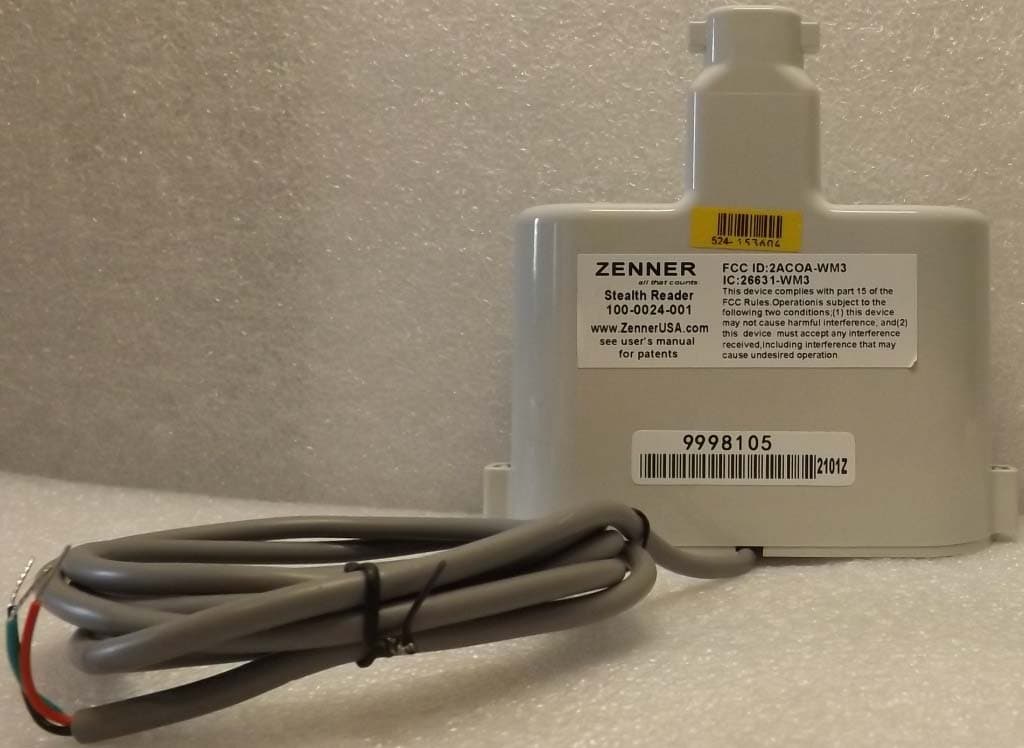
2ACOA-WM3
Jul 29, 2021Digital Transceiver
Equipment Class
DTS - Digital Transmission System
2ACOA-OD2
Mar 14, 2021IoT gateway
Equipment Class
DTS - Digital Transmission System