2ACRG-39859F49RC HOVERCRAFT
ECHO TECHNOLOGIES ASIA LTD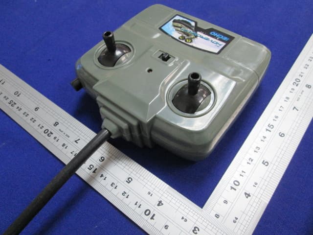
Click to zoom
Application Details
- Equipment Class
- DXX - Part 15 Low Power Communication Device Transmitter
- Date of Grant
- Aug 26, 2014
- Application Purpose
- Original Equipment
- Date of Application
- Aug 26, 2014
- Equipment Note
- RC HOVERCRAFT
- Frequency Range
- 49.86000000 - 49.86000000
- Company
- ECHO TECHNOLOGIES ASIA LTD
- Country
- Hong Kong
Documents & Files
Document Text
Text extracted from the exhibit documents filed with the FCC. Open a document above to read the original.
Users Manual
Table of Contents Component Checklist 1. Warranty Information 4. Trouble Shooting & Support 3. Precautions and Care 2. Proper Use Support Battery Installation 7.8. 9. Hovercraft Features and Functions Hovercraft Features and Functions Hovercraft Battery Installation Features and Functions 6. Transmitter Battery Charging 5. Battery Pack 39859 OWNER’S MANUAL Please read and understand before operating your Hovercraft as it contains important information. Thank you for choosing ECHO Technologies! CAUTION – ELECTRICALLY OPERATED: NOT RECOMMENDED FOR CHILDREN UNDER 8 YEARS HANDLE WITH CAUTION TO PREVENT ELECTRIC SHOCK. INPUT: 120V AC 60HZ 10W. OUTPUT: 12V DC 350mA. To ensure expedited assistance, First, please visit our website: www.toysinquiry.com to submit any questions or comments. This would be the quickest way to get a response and assistance. If the problem is not resolved in such manner, then please call toll-free: 1-800-434-6178. DO NOT RETURN TO STORE THIS PRODUCT CANNOT BE RETURNED FOR A REFUND AFTER IT HAS BEEN UNPACKED AND USED. LAND AND WATER SPEEDSTER Page 1: Table of Contents and Components Checklist Page 2: Proper Use - Precautions and Care Page 3: Trouble Shooting and Support Page 4: Warranty Information Page 5: Battery Charging Page 6: Transmitter Battery Installation, Features and Functions Page 7: Hovercraft Battery Installation Page 8: Hovercraft Features and Functions Page 9: Hovercraft Features and Functions Please check to make sure all contents are complete Transmitter Hovercraft 9.6 V Rechargeable Battery Pack Battery Charger 9V Battery SOLVENT WATER MINERAL SPIRITS Do not use chemicals or water to clean. Safety Tips: This toy is recommended for children 8 years of age and older. To ensure that the child’s play is both safe and fun, please review the operating instructions and these general safety rules with the child. Gently brush areas where dirt is trapped. Wipe down body with soft cloth. Switch OFF Transmitter and Vehicle when not in use. Avoid running on thick carpeting. Avoid water puddles, wet grass or rain. DO NOT pick up while in motion. Prohibition under 8 years old child usage. UNDER 8 YEARS OLD Keep fingers, hair and loose clothing away from the propeller while the Hovercraft is switched “ON”. Do not leave in direct sunlight for long periods as damage may occur. Avoid Sand, Salt and Mud. Avoid collisions with hard surfaces. Store in cool dry place and away from direct heat sources. Handle carefully, DO NOT drop it. Issue – No response or slow movements - Ensure that the ON/OFF switch is in the “ON” position - Ensure that fresh alkaline battery is in the transmitter and has been installed correctly, sometimes giving it a nudge or reinserting the batteries may solve the issue. - Is the Rechargeable Battery Pack installed correctly in the vehicle? - (+) and (-) contacts in the Transmitter Battery Compartment MUST be aligned correctly with the (+) and (-) contacts on the Alkaline Battery. - (+) and (-) contacts in the Vehicle Battery Compartment MUST be aligned correctly with the (+) and (-) contacts on the Vehicle Battery Pack. - Are all battery contact points touching? Please ensure that the contact points are neither rusty nor dirty. Issue – Erratic or Unpredictable Behavior - If the vehicle moves by itself or exhibits reduced transmission range, please ensure that there is no external interference in the area. To do this, take the vehicles away from any power lines, tall buildings or radio towers to reduce radio interference. Issue – Short Battery Life Ensure that the battery is fully charged. The included 9.6V Vehicle Battery is NOT charged prior to shipment, please charge for 8 hours (first two full charges) out of the box. Subsequent charges will only require 4 hours. If the Battery Pack is Hot or Warm Please DO NOT recharge, allow the Vehicle Battery Pack to cool down before recharging, otherwise, it will reduce the life of the Vehicle Battery Pack. Damaged Vehicle Battery Pack Please DO NOT recharge if the Vehicle Battery Pack appears to be damaged or leaking. When NOT in use Always unplug Vehicle Battery Pack Charger from the power outlet. Always remove any batteries from the Transmitter and the Vehicle. Battery Safety Precautions DO NOT dispose any type of batteries in fire, leakage, explosion and personal injury may occur. Dispose of Rechargeable Battery Packs properly. DO NOT take apart Rechargeable Battery Packs. DO NOT use the Battery Charger other than instructed in this Owner’s Manual. Adult supervision strongly recommended when charging batteries. DO NOT attempt jumps or crashes with this vehicle as this may dislodge the battery connections. Best way to contact us is via our website: www.toysinquiry.com. TOLL-FREE NUMBER: 1-800-434-6178 Hours: 8:30 A.M. – 5:00 P.M. Central Time; Monday – Friday, except Public Holidays. Expect some delay during peak seasons. Please be patient. Address for Returns: Toys Inquiry 1800 North, 9th Street, Indianola, IA 50125 FCC Statement This device complies with Part 15 of the FCC Rules. Operation is subject to the following two conditions: (1) This device may not cause harmful interference, and (2) This device must accept any interference received, including interference that may cause undesired operation. WARNING: Changes or modifications to this unit not expressly approved by the party responsible for compliance could void the user’s authority to operate the equipment. The manufacture is not responsible for any radio or TV interference caused by unauthorized modifications to this equipment. NOTE: This equipment has been tested and found to comply with the limits for a Class B digital device, pursuant to Part 15 of the FCC Rules. These limits are designed to provide reasonable protection against harmful interference in a residential installation. This equipment generates, uses and can radiate radio frequency energy and, if not installed and used in accordance with the instructions, may cause harmful interferen…
Text truncated - open the document above for the full version.
Block Diagram
49.86MHz Transmitter Block Diagram IC1 49.86 49.86
External Photos
External Photos
ID Label/Location Info
Label Artwork and Location SIZE: 46mm (W) x 12mm (H) FCC ID: 2ACRG-39859F49 This device complies with Part 15 of the FCC Rules. Operation is subject to the following two conditions: (1) this device may not cause harmful interference, and (2) this device must accept any interference received, including interference that may cause undesired operation.
Internal Photos
Internal Photos
Operational Description
Technical description Description Function Component Antenna Transmit modulated RF signal ANT Filter Suppression of spurious emissions L1, T1, C1, C2, C3 RF IC Generate code signal to modulator IC1 Oscillator Generate 49.86 MHz carrier Y1, Q1 RF power amplifier and modulator Modulate the carrier and amplify the modulated RF signal Q2 Antenna Type: Integral antenna with plastic enclosure Antenna Gain: 0dBi Modulation Type: Pulse modulation The nominal conducted output power specified: -43.00dBm (+/- 3dB) The nominal radiated output power (e.r.p) specified: -45.15dBm (+/- 3dB)
RF Exposure Info
1 INTERTEK TESTING SERVICES Analysis Report The equipment under test (EUT) is a portable transmitter for a RC Hovercraft operating at 49.86 MHz which is controlled by a crystal. The EUT is powered by one 9.0V 6F22 size battery. For more detail information pls. refer to the user manual. Antenna Type: Integral antenna with plastic enclosure Antenna Gain: 0dBi The nominal conducted output power specified: -43.00dBm (+/- 3dB) The nominal radiated output power (e.r.p) specified: -45.15dBm (+/- 3dB) Modulation Type: Pulse modulation According to the KDB 447498: The worst-case peak radiated emission for the EUT is 51.8dBμV/m at 3m in the frequency 49.86MHz The EIRP = [(FS*D) ^2 / 30] mW= -43.43dBm The ERP = EIRP – 2.15 = -45.58 dBm which is within the production variation. The maximun conducted output power specified is -40dBm =0.0001mW The source- based time-averaging conducted output power = 0.0001* Duty Cycle mW < 0.1 mW (Duty Cycle<100%) The SAR Exclusion Threshold Level for 49.860MHz when the minimum test separation distance is < 50mm: = 474 * [1 + log(100/f(MHz)]/2 = 308.6 mW Since the source-based time-averaging conducted output power is well below the SAR low threshold level, so the EUT is considered to comply with SAR requirement without testing. Transmitter Duty Cycle Calculation The duration of one cycle = 17.5362ms Effective period of the cycle = 507.2μs x 10 + 1.4493ms x 4 = 10.8692ms DC = 10.8692ms / 17.5362ms = 0.6198 or 61.98% FCC ID: 2ACRG-39859F49
Schematics
Transmitter Circuit Diagram 49.860MHz IC1 NC 49.860MHz
Test Report
Date: 21.JUL.2014 16:48:41 Date: 21.JUL.2014 16:51:30 Date: 21.JUL.2014 16:52:17 Date: 21.JUL.2014 16:51:53
Test Report
The test results reported in this test report shall refer only to the sample actually tested and shall not refer or be deemed to refer to bulk from which such a sample may be said to have been obtained. This report is for the exclusive use of Intertek's Client and is provided pursuant to the agreement between Intertek and its Client. Intertek's responsibility and liability are limited to the terms and conditions of the agreement. Intertek assumes no liability to any party, other than to the Client in accordance with the agreement, for any loss, expense or damage occasioned by the use of this report. Only the Client is authorized to copy or distribute this report. Any use of the Intertek name or one of its marks for the sale or advertisement of the tested material, product or service must first be approved in writing by Intertek. The observations and test results referenced from this report are relevant only to the sample tested. This report by itself does not imply that the material, product, or service is or has ever been under an Intertek certification program. For Terms And Conditions of the services, it can be provided upon request. The evaluation data of the report will be kept for 3 years from the date of issuance. TRF No.: FCC 15C_TX_b Intertek Testing Services Shenzhen Ltd. Kejiyuan Branch 6F, D Block, Huahan Building, Langshan Road, Nanshan District, Shenzhen, P. R. China Tel: (86 755) 8601 6288 Fax: (86 755) 8601 6751 ECHO TECHNOLOGIES ASIA LTD Application For Certification FCC ID: 2ACRG-39859F49 RC HOVERCRAFT Model: 39859-49MHZ Transmitter Report No.: SZHH00887735-001 We hereby certify that the sample of the above item is considered to comply with the requirements of FCC Part 15, Subpart C for Intentional Radiator, mention 47 CFR [10-1-13] Prepared and Checked by: Approved by: Sign on file Abel Zhou Assistant Engineer Andy Yan Senior Project Engineer Date: August 15, 2014 INTERTEK TESTING SERVICES Report No.:SZHH00887735-001 FCC ID: 2ACRG-39859F49 TRF No.: FCC 15C_TX_b i GENERAL INFORMATION ECHO TECHNOLOGIES ASIA LTD MODEL: 39859-49MHZ FCC ID: 2ACRG-39859F49 Grantee: ECHO TECHNOLOGIES ASIA LTD Grantee Address: 8/F 601-603 Tai Nan West Street Kowloon Hong Kong Contact Person: Sylvia Wong Tel: 0852-23707286 Manufacturer: ECHO TECHNOLOGIES ASIA LTD Manufacturer Address: 8/F 601-603 Tai Nan West Street Kowloon Hong Kong Model: 39859-49MHZ Type of EUT: Transmitter Description of EUT: RC HOVERCRAFT Serial Number: N/A FCC ID : 2ACRG-39859F49 Date of Sample Submitted: July 16, 2014 Date of Test: July 21, 2014 Report No.: SZHH00887735-001 Report Date: August 15, 2014 Environmental Conidtions: Temperature: +10 to 40°C Humidity: 10 to 90% INTERTEK TESTING SERVICES Report No.:SZHH00887735-001 FCC ID: 2ACRG-39859F49 TRF No.: FCC 15C_TX_b ii SUMMARY OF TEST RESULT ECHO TECHNOLOGIES ASIA LTD MODEL: 39859-49MHZ FCC ID: 2ACRG-39859F49 TEST SPECIFICATION REFERENCE RESULTS Maximum Peak Output Power 15.247(b), (c) / RSS-210 A8.4 N/A Hopping Channel Carrier Frequencies Separation (for 2.4GHz Digital) 15.247(e) / RSS-210 A8.1 N/A 20dB Bandwidth of the Hopping Channel 15.247(a) / RSS-210 A8.1 N/A Number of Hopping Frequencies 15.247(e) / RSS-210 A8.1 N/A Average Time of Occupancy of Hopping Frequency 15.247(e) / RSS-210 A8.1 N/A Anteann Conducted Spurious Emissions 15.247(d) / RSS-210 A8.5 N/A Radiated Spurious Emissions 15.247(d) / RSS-210 A8.5 N/A RF Exposure Compliance 15.247(i) / RSS-Gen 5.5 N/A Transmitter Power Line Conducted Emissions 15.207 / RSS-Gen 7.2.2 N/A Transmitter Field Strength (for 27MHz) 15.227 / RSS-310 3.8 N/A Transmitter Field Strength (for 40MHz) 15.229 / RSS-210 A2.7 N/A Transmitter Field Strength, Bandwidth and Timing Requirement (for Remote Control) 15.231(a) / RSS-210 A1.1.1 N/A Transmitter Field Strength, Bandwidth and Timing Requirement (for 433MHz) 15.231(e) / RSS-210 A1.1.5 N/A Transmitter Field Strength and Bandwidth Requirement(for 88-108MHz) 15.239 / RSS-210 A2.8 N/A Transmitter Field Strength and Bandwidth Requirement(for 902- 928MHz or 2.4GHz) 15.249 / RSS-210 A2.9 N/A Transmitter Field Strength and Bandwidth Requirement (for 49MHz) 15.235 / RSS-310 3.9 Pass Receiver / Digital Device Radiated Eissions 15.109 / ICES-003 N/A Digital Device Conducted Emissions 15.107 / ICES-003 N/A Note: 1. The EUT uses an Integral antenna which, in accordance to section 15.203, is considered sufficient to comply with the pervisions of this section. 2. Pursuant to FCC part 15 Section 15.215(c), the 20 dB bandwidth of the emission was contained within the frequency band designated (mentioned as above) which the EUT operated. The effects, if any, from frequency sweeping, frequency hopping, other modulation techniques and frequency stability over excepted variations in temperature and supply voltage were considered. INTERTEK TESTING SERVICES Report No.:SZHH00887735-001 FCC ID: 2ACRG-39859F49 TRF No.: FCC 15C_TX_b iii Table of Contents 1.0 General Description ....................................................................................... 1 1.1 Product Description .......................................................................................... 1 1.2 Related Submittal(s) Grants .............................................................................. 1 1.3 Test Methodology ............................................................................................. 1 1.4 Test Facility ...................................................................................................... 1 2.0 System Test Configuration ............................................................................ 2 2.1 Justification ...................................................................................................... 2 2.2 EUT Exercising Software .................................................................................. 2 2.3 Special Accessories ......................................................................................... 2 2.4 Equipment Modif…
Text truncated - open the document above for the full version.
Test Setup Photos
Radiated Photos
Contact Information
Applicant
Sylvia Wong(General Manager)
Technical Contact
Intertek Testing Services Shenzhen Ltd. Kejiyuan BShawn Xing
[email protected](86-755) 8614 0603
6F, D Block, Huahan Building, Langshan Road · Shenzhen · China
Non-Technical Contact
Intertek Testing Services Shenzhen Ltd. Kejiyuan BShawn Xing
[email protected](86-755) 8614 0603
Test Firm
Intertek Testing Services Shenzhen Ltd.Shawn Xing
Technical Specifications
| # | Rule Parts | Frequency Range | Power Output |
|---|---|---|---|
| 1 | 15C | 49.86 MHz - 49.86 MHz | - |
Other Applications from ECHO TECHNOLOGIES ASIA LTD
2ACRG-39857F27
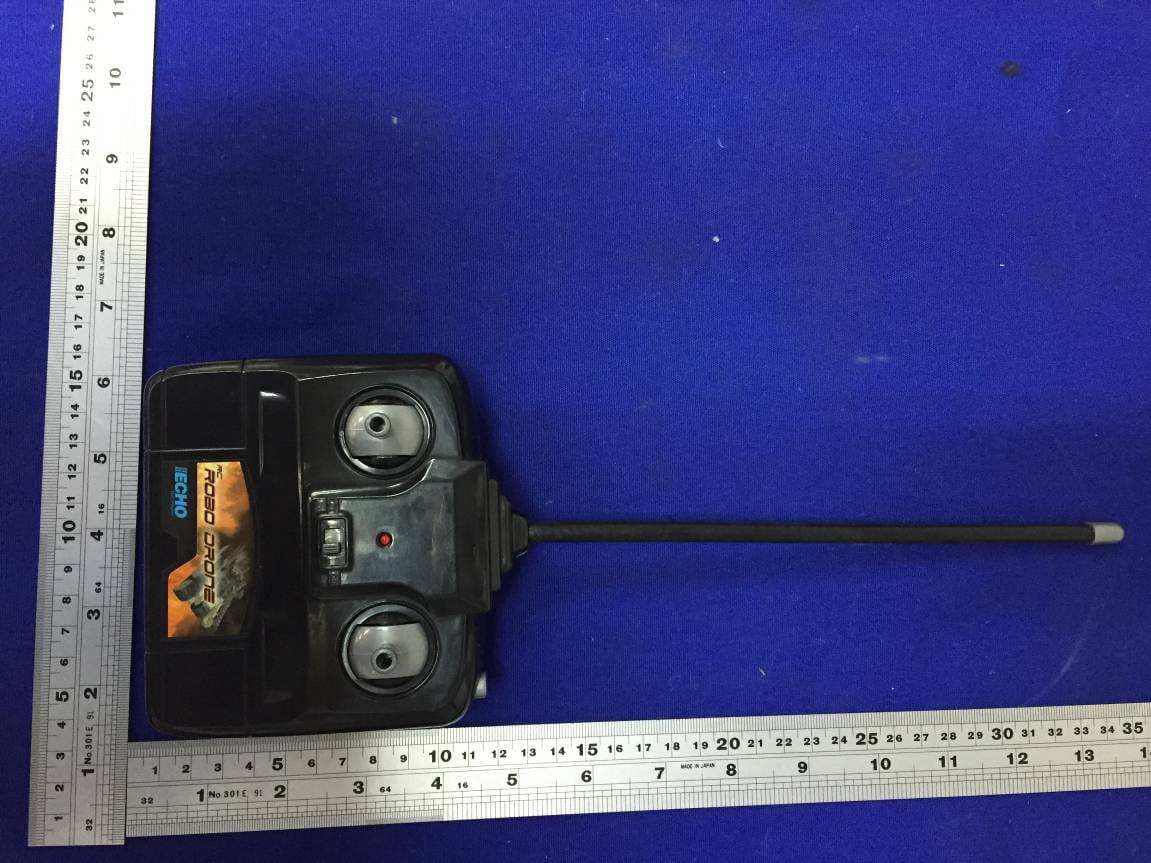
Jul 05, 2015RC ROBO DRONE
Equipment Class
DXX - Part 15 Low Power Communication Device Transmitter
2ACRG-39859H49
Aug 26, 2014RC HOVERCRAFT
Equipment Class
CRR - Superregenerative Receiver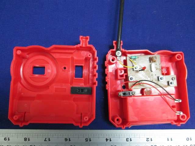
2ACRG-34361F49
Aug 03, 2014RC Street Shredder
Equipment Class
DXX - Part 15 Low Power Communication Device Transmitter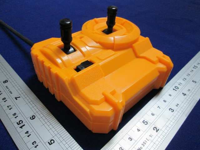
2ACRG-34360F49
Aug 03, 2014RC Carboto
Equipment Class
DXX - Part 15 Low Power Communication Device Transmitter
2ACRG-34361H49
Aug 03, 2014RC Street Shredder
Equipment Class
CRR - Superregenerative Receiver