2ACSOGDRD5Y6YDPulse Radar Level Instrument
Beijing GODA Instruments Co., LTD.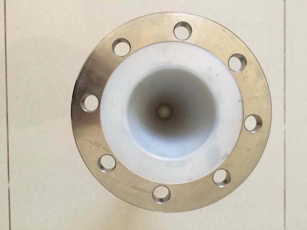
Click to zoom
Application Details
- Equipment Class
- LPR - Level Probing Radar
- Date of Grant
- Jun 04, 2015
- Application Purpose
- Original Equipment
- Date of Application
- Jun 04, 2015
- Equipment Note
- Pulse Radar Level Instrument
- Frequency Range
- 6300.00000000 - 6300.00000000
- Country
- China
Documents & Files
Document Text
Text extracted from the exhibit documents filed with the FCC. Open a document above to read the original.
Users Manual
Beijing GODA Instruments Co.,Ltd. 北京古大仪表有限公司 Level Measurement Expert 6GHz Pulse Radar Level Instrument Table of Contents 1 For your safety...... ............... ....1 2 Measurement Principle ................ ...2 3 Mounting Requirement................. ...3 4 Electrical Connection.................. ....9 6 Adjustment Instructions................. . .11 9 Selection & Ordering Information............ 14 1 1.For your safety All operations described in this operating instructions manual must be carried out ouly by trained specialist personnel authorised by the plant operator. During work on and with the device the required personal protective equipment must always be worn. Operational reliability is ensured only if the instrument is properly used according to the specifications in the operating instructions manual as well as possible supplementary instructions. This device complied with Part 15 of the FCC Rules. Operation is subject to the following two conditions: (1)this device may not cause harmful interference, and (2)this device must accept any interference received, including interference that may cause undesired operation. Changes or modifications not expressly approved by the manufacturer could void the user's authority to operate the equipment. Authorised personal Appropriate use FCC Certification Warning: User must keep a safety distance of at least 20cm from the antenna. NOTE: This equipment has been tested and found to comply with the limits for a Class A digital device, pursuant to part 15 of the FCC Rules. These limits are designed to provide reasonable protection against harmful interference when the equipment is operated in a commercial environment. This equipment generates, uses, and can radiate radio frequency energy and, if not installed and used in accordance with the instruction manual, may cause harmful interference to radio communications. Operation of this equipment in a residential area is likely to cause harmful interference in which case the user will be required to correct the interference at his own expense. 2.Measurement Principle Principle Features The extremely narrow microwave pulse emitted by the antenna on radar level instrument can travel at the speed of light and part of its energy, which is reflected off the surface of target medium, is received by the very same antenna. The time lapse between pulse emission and reception by the antenna is proportional to the distance between the surface of target medium and the reference point on antenna. However, due to the fact that the electromagnetic wave is transmitted at extremely high speed, which leads to the tiny time lapse (nanosecond level) and makes it difficult to be identified,GDRD5X series of radar level instrument have adopted a special demodulation technology, enabling itself to detect the time lapse between pulse emission and reception correctly, and eventually generate accurate measurement result. Equipped with advanced microprocessor and unique EchoDiscovery echo processing technology, the radar level instrument can be used under various hazardous process conditions. The false echo storage function enables the instrument to detect the true echo with the presence of multiple false echoes and eventually generate accurate measurement results. There are multiple options available in choosing various process connection and detection component, which enables GDRD5X series radar level instrument to be applied in a broad array of hazardous applications, such as high temperature, high pressure, small dielectric constant and so on. The guided wave radar level instrument, with pulses as its working tool and extremely low emission power, can be mounted on various metal or nonmetal vessels, harmless towards the environment and human beings. 2 There is a certain existing beam angle while the antenna transmitting microwave pulses. There should beno barriers between the lower edge of antenna and surface of measuredmedium. Therefore it is highly recommended to avoid facilities inside vessels, such asladders, limit switches, heating spirals, struts and etc, during the mounting process. “False echo learning” must be carried out during the installation in this case.Furthermore, microwave beams must NOT intersect the filling streams. Be cautions duringthe installation: the highest level of target medium must NOT enter into blanking zone; the instrument must keep certain distance to vessel walls; every possible measure needs to be taken to position the instrument so that the direction of antenna emission is perpendicular to the surface of measured medium. The installation of instruments in xplosion proof area must abide by relevant local or federal safety regulations. Aluminum housing should be used for intrinsically safe explosion proof version, which is also applicable in explosion proof areas. The instrument must be connected with ground in this case. Note:The highest level of measured medium must not enter into vlanking zone while radar level measurement instrument is in operation. 1.Reference Plane 2.Center of Vessel or Symmetrical Axis Minium distance of 500mm between instrument and vessel wall during installation >500mm 1 2 3 3.Mounting Requirements Basic Requirements The reference plane is the thread or flange surface 100% 0% 11111111 2222 33 3 33 4 Illustrations Mounting Position 1. Blanking Zone(menu1.9) 2. Empty(menu1.8) 3. Max. Adjustment(menu1.2) 4. Min. Adjustment(menu1.1) 6GHz Pulse Radar Level Instrument The best mounting position for a conical vessel with flat top is the center of its top, as the effective measurement can reach the bottom of vessel. In order to avoid dampness under outdoor or humid indoor conditions or for those instruments mounted on cooling/heating vessels, seal rings used on cables should be screwed tight, plus the cable must be bended downward outside cable entry, indicated on the diagram below >500mm 1 2 Damp-proof 4 1.Reference Plane 2.Center of Vessel or Symmetrical Axis Socket Th…
Text truncated - open the document above for the full version.
External Photos
EXTERNAL PHOTO DOCUMENTATION 16804256 001 for Pulse Radar Level Instrument Beijing GODA Instruments Co., LTD. This documentation consists of 2 pages (excluding this cover page). Photo Documentation Report Number: 16804256 001 Model: Pulse Radar Level Instrument - Page 1 of 2 1 Front view of GDRD53 series 2 Side view of GDRD53 series Photo Documentation Report Number: 16804256 001 Model: Pulse Radar Level Instrument - Page 2 of 2 3 Top view of GDRD53 series 4 Bottom view of GDRD53 series
ID Label/Location Info
For GDRD53 series: WARNING label: ID Label:
Internal Photos
INTERNAL PHOTO DOCUMENTATION 16804256 001 for Pulse Radar Level Instrument Beijing GODA Instruments Co., LTD. This documentation consists of 9 pages (excluding this cover page). Photo Documentation Report Number: 16804256 001 Model: Pulse Radar Level Instrument - Page 1of 9 For GDRD53 series: 1 antenna with electronic part 2 antenna with connector top view Photo Documentation Report Number: 16804256 001 Model: Pulse Radar Level Instrument - Page 2of 9 3 electronic part front view 4 electronic part top view Photo Documentation Report Number: 16804256 001 Model: Pulse Radar Level Instrument - Page 3of 9 5 electronic part back view 6 electronic part bottom view Photo Documentation Report Number: 16804256 001 Model: Pulse Radar Level Instrument - Page 4of 9 7 PCB POWER BOARD top view with shielding 8 PCB POWER BOARD top view without shielding Photo Documentation Report Number: 16804256 001 Model: Pulse Radar Level Instrument - Page 5of 9 9 PCB POWER BOARD bottom view 10 PCB MCU BOARD top view Photo Documentation Report Number: 16804256 001 Model: Pulse Radar Level Instrument - Page 6of 9 11 PCB MCU BOARD bottom view 12 PCB DISPLAY BOARD top view Photo Documentation Report Number: 16804256 001 Model: Pulse Radar Level Instrument - Page 7of 9 13 PCB DISPLAY BOARD bottom view 14 PCB HF BOARD top view with shielding Photo Documentation Report Number: 16804256 001 Model: Pulse Radar Level Instrument - Page 8of 9 15 PCB HF BOARD bottom view with shielding 16 PCB HF BOARD top view without shielding Photo Documentation Report Number: 16804256 001 Model: Pulse Radar Level Instrument - Page 9of 9 17 PCB HF BOARD bottom view without shielding
Test Report
Produkte Products TÜV Rheinland (China) Ltd. Avic 707, Beijing Tel.: 010-65666660 Fax: 010-65666667 Mail: service-gc@ tuv.com Web: www.chn.tuv.comom Prüfbericht-Nr.: Test Report No.: 16804256 001 Auftrags-Nr.: Order No.: 1140013772 Seite 1 von 18 Page 1 of 18 Kunden-Referenz-Nr.: Client Reference No.: 412990 Auftragsdatum: Order date: 2014-06-18 Auftraggeber: Client: Beijing GODA Instruments Co., LTD. Hongfu Enterprise Incubation Yard 10, No.2 Workshop 2-4, Chang Ping Dist, Beijing 102209 P.R. China Prüfgegenstand: Test item: Pulse Radar Level Instrument Bezeichnung / Typ-Nr.: Identification / Type No.: Refer to section 2.2 Auftrags-Inhalt: Order content: FCC certification Prüfgrundlage: Test specification: FCC Part 15 Subpart C Section 15.209 Wareneingangsdatum: Date of receipt: 2014-10-16 Prüfmuster-Nr.: Test sample No.: Engineering sample Prüfzeitraum: Testing period: 2014-10-16 to 2014-10-21 Ort der Prüfung: Place of testing: Refer to section 1.1 Prüflaboratorium: Testing laboratory: Refer to section 1.1 Prüfergebnis*: Test result*: Pass Refer to external photo geprüft von / tested by: 2014-12-09 Wang, Gang/ PE kontrolliert von / reviewed by: 2014-12-09 Sun, Lixun/Reviewer Datum Date Name / Stellung Name / Position Unterschrift Signature Datum Date Name / Stellung Name / Position Unterschrift Signature Sonstiges / Other: Zustand des Prüfgegenstandes bei Anlieferung: Condition of the test item at delivery: Prüfmuster vollständig und unbeschädigt Test item complete and undamaged * Legende: 1 = sehr gut 2 = gut 3 = befriedigend 4 = ausreichend 5 = mangelhaft P(ass) = entspricht o.g. Prüfgrundlage(n) F(ail) = entspricht nicht o.g. Prüfgrundlage(n) N/A = nicht anwendbar N/T = nicht getestet Legend: 1 = very good 2 = good 3 = satisfactory 4 = sufficient 5 = poor P(ass) = passed a.m. test specification(s) F(ail) = failed a.m. test specification(s) N/A = not applicable N/T = not tested Dieser Prüfbericht bezieht sich nur auf das o.g. Prüfmuster und darf ohne Genehmigung der Prüfstelle nicht auszugsweise vervielfältigt werden. Dieser Bericht berechtigt nicht zur Verwendung eines Prüfzeichens. This test report only relates to the a. m. test sample. Without permission of the test center this test report is not permitted to be duplicated in extracts. This test report does not entitle to carry any test mark. Produkte Products Prüfbericht - Nr.: Test Report No. 16804256 001 Seite 2 von 18 Page 2 of 18 TEST SUMMARY 4.1.1 RADIATED EMISSION RESULT: Passed 4.2.1 ELECTROMAGNETIC FIELDS RESULT: Passed Produkte Products Prüfbericht - Nr.: Test Report No. 16804256 001 Seite 3 von 18 Page 3 of 18 Contents 1. TEST SITES ...................................................................................................................... 4 1.1 TEST FACILITIES ............................................................................................................... 4 1.2 LIST OF TEST AND MEASUREMENT INSTRUMENTS ............................................................... 4 1.3 TRACEABILITY .................................................................................................................. 5 1.4 CALIBRATION ................................................................................................................... 5 1.5 MEASUREMENT UNCERTAINTY........................................................................................... 5 2. GENERAL PRODUCT INFORMATION .................................................................................... 6 2.1 PRODUCT FUNCTION AND INTENDED USE ........................................................................... 6 2.2 RATINGS AND SYSTEM DETAILS ........................................................................................ 6 2.3 INDEPENDENT OPERATION MODES .................................................................................... 8 2.4 NOISE GENERATING AND NOISE SUPPRESSING PARTS ....................................................... 8 2.5 SUBMITTED DOCUMENTS .................................................................................................. 8 3. TEST SET-UP AND OPERATION MODES .............................................................................. 9 3.1 PRINCIPLE OF CONFIGURATION SELECTION ........................................................................ 9 3.2 TEST OPERATION AND TEST SOFTWARE ............................................................................ 9 3.3 SPECIAL ACCESSORIES AND AUXILIARY EQUIPMENT .......................................................... 9 3.4 COUNTERMEASURES TO ACHIEVE EMC/RF COMPLIANCE ................................................. 10 3.5 TEST SETUP DIAGRAM .................................................................................................... 10 4. TEST RESULTS ............................................................................................................... 11 4.1 TRANSMITTER REQUIREMENT & TEST SUITES .................................................................. 11 4.1.1 Radiated Emission ..................................................................................................................... 11 4.2 RADIO FREQUENCY EXPROSURE COMPLIANCE................................................................. 17 4.2.1 Electromagnetic Fields ............................................................................................................... 17 5. LIST OF TABLES ............................................................................................................. 18 6. LIST OF FIGURES ............................................................................................................ 18 Produkte Products Prüfbericht - Nr.: Test Report No. 16804256 001 Seite 4 von 18 Page 4 of 18 1. Test Sites 1.1 Test Facilities Laboratory 1: TA Beijing Limited (FCC Registration No.: 413514) Address: Building B-4, No.1, JingHai 3rd Road, BDA East ParK,Beijing, 100176 China Laboratory 2: The …
Text truncated - open the document above for the full version.
Test Setup Photos
Produkte Products Prüfbericht - Nr.: Test Report No. 16804256 001 Seite 1 von 4 Page 1 of 4 1. Photographs of the Test Set-Up Photograph 1: Set-up for Radiated Spurious Emissions, below 1GHz Produkte Products Prüfbericht - Nr.: Test Report No. 16804256 001 Seite 2 von 4 Page 2 of 4 Photograph 2: Set-up for Spurious Emissions,above 1GHz 1-18GHz 18-26.5GHz Produkte Products Prüfbericht - Nr.: Test Report No. 16804256 001 Seite 3 von 4 Page 3 of 4 26.5-40GHz Produkte Products Prüfbericht - Nr.: Test Report No. 16804256 001 Seite 4 von 4 Page 4 of 4 Photograph 3: EUT position on testing tank
Contact Information
Applicant
Zhidu Zhou(Director of International Sales)
Test Firm
The State Radio_Monitoring_Center Testing (SRTC)Junfeng Wang
Technical Specifications
| # | Rule Parts | Frequency Range | Power Output |
|---|---|---|---|
| 1 | 15.209 | 6.30 GHz - 6.30 GHz | 29.40 µW |
Other Applications from Beijing GODA Instruments Co., LTD.
2ACSOGDRD5X6XC
Jan 26, 2015Pulse Radar Level Instrument
Equipment Class
LPR - Level Probing Radar
2ACSOGDRD5X6XA
Sep 21, 2014Pulse Radar Level Instrument
Equipment Class
LPR - Level Probing Radar