2ACSZSPMFLEXRFID Chemcassette Recognition
Honeywell Analytics Inc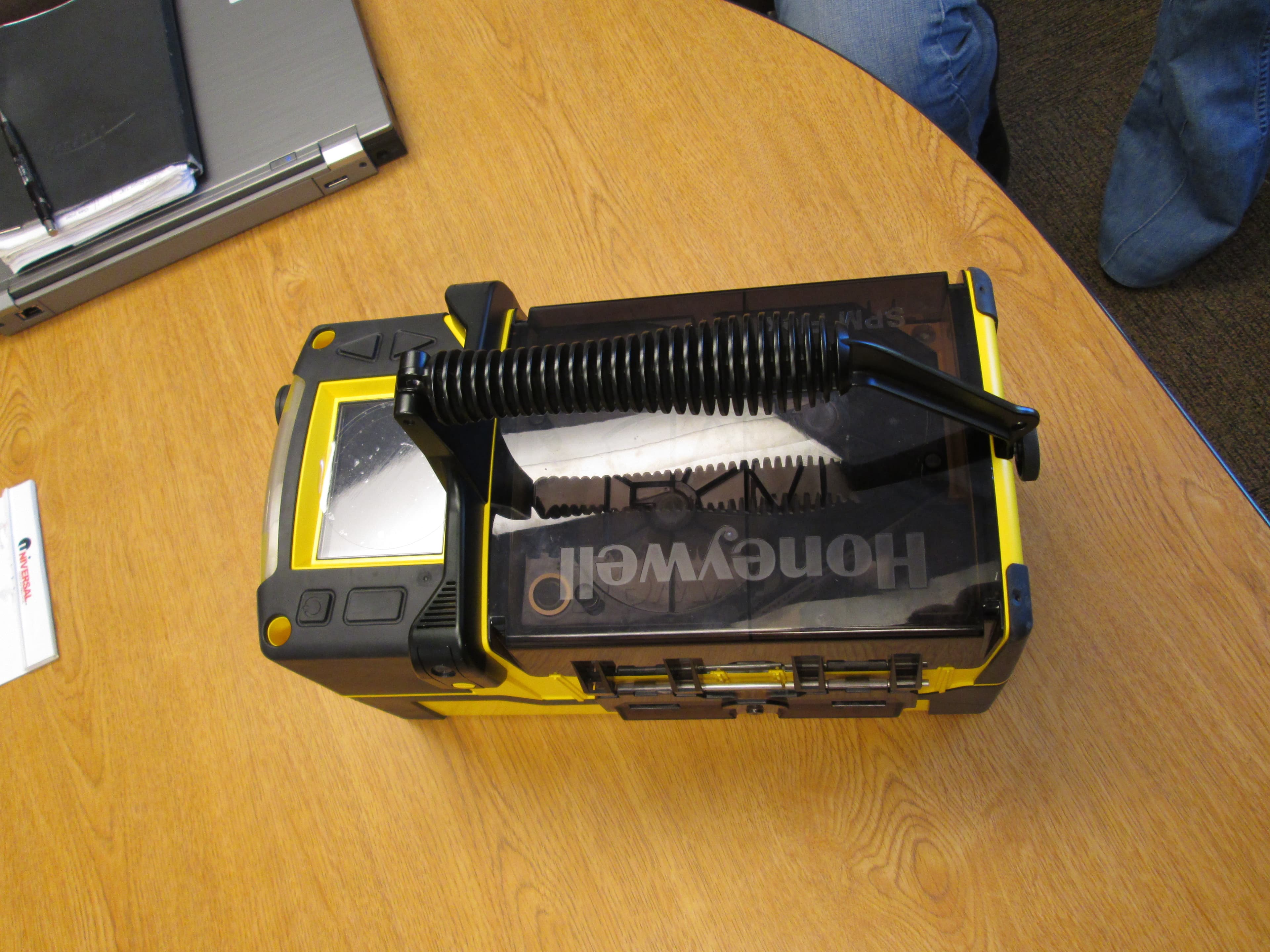
Click to zoom
Application Details
- Equipment Class
- DXX - Part 15 Low Power Communication Device Transmitter
- Date of Grant
- Sep 01, 2014
- Application Purpose
- Original Equipment
- Date of Application
- Aug 29, 2014
- Equipment Note
- RFID Chemcassette Recognition
- Frequency Range
- 13.56000000 - 13.56000000
- Company
- Honeywell Analytics Inc
- Country
- United States
Documents & Files
Document Text
Text extracted from the exhibit documents filed with the FCC. Open a document above to read the original.
Users Manual
SPM Flex Single Point Monitor Gas Detector User’s Manual 3 SPM Flex Gas Detector Introduction ����������������������������������������������������������������������������������������������������������������5 Safety Information ��������������������������������������������������������������������������������������������������6 Contact Information ������������������������������������������������������������������������������������������������7 Glossary ����������������������������������������������������������������������������������������������������������������������8 Product Overview �������������������������������������������������������������������������������������������������������9 Battery operation ��������������������������������������������������������������������������������������������������10 The handle (portable model) ��������������������������������������������������������������������������������11 Opening the cover ������������������������������������������������������������������������������������������������11 Main power rocker switch ������������������������������������������������������������������������������������12 Turning the detector on and off ����������������������������������������������������������������������������13 Navigation �������������������������������������������������������������������������������������������������������������14 Menu Map �������������������������������������������������������������������������������������������������������������15 Wiring and tubing �����������������������������������������������������������������������������������������������������19 Typical fixed installation topologies ���������������������������������������������������������������������19 Wiring diagrams ����������������������������������������������������������������������������������������������������21 4-20 mA wiring ������������������������������������������������������������������������������������������������������22 Modbus register definitions ����������������������������������������������������������������������������������24 Setup �������������������������������������������������������������������������������������������������������������������������26 Installation drawing �����������������������������������������������������������������������������������������������26 Mounting options ��������������������������������������������������������������������������������������������������26 Dimensions ������������������������������������������������������������������������������������������������������������27 Standard mounting bracket ����������������������������������������������������������������������������������28 Backward-compatible mounting bracket ������������������������������������������������������������29 In-line filters �����������������������������������������������������������������������������������������������������������30 Optional sampling wand ���������������������������������������������������������������������������������������30 Attaching the shoulder strap ��������������������������������������������������������������������������������31 Operation �����������������������������������������������������������������������������������������������������������������32 Controls �����������������������������������������������������������������������������������������������������������������32 Setup menu �����������������������������������������������������������������������������������������������������������38 Troubleshooting ��������������������������������������������������������������������������������������������������������42 Maintenance �������������������������������������������������������������������������������������������������������������46 Storing the detector ����������������������������������������������������������������������������������������������49 Recycling ���������������������������������������������������������������������������������������������������������������49 Storing Chemcassette ® cartridges �����������������������������������������������������������������������49 Labels ������������������������������������������������������������������������������������������������������������������������50 Detectable Gases �����������������������������������������������������������������������������������������������������51 Specifications ����������������������������������������������������������������������������������������������������������52 Accessories and Parts ���������������������������������������������������������������������������������������������53 Certifications ������������������������������������������������������������������������������������������������������������56 Warranties �����������������������������������������������������������������������������������������������������������������62 SPM Flex warranty ������������������������������������������������������������������������������������������������62 Chemcassette ® cartridge warranty ����������������������������������������������������������������������62 Index �������������������������������������������������������������������������������������������������������������������������64 4 SPM Flex Gas Detector 5 SPM Flex Gas Detector Introduction The SPM Flex gas detector is an extractive gas monitoring system that draws gas samples locally or from a remote point to a Chemcassette ® tape-based optical gas detection system� A wide range of toxic gas Chemcassette cartridges are available that enable detection of gases used or generated in semiconductor manufacturing and industrial environments � The SPM Flex gas detector, available in wall mounted and portable versions, locally displays gas concentration, alarm, fault and status information via its backlit color LCD and LEDs� A simple to use 4-button keypad adjacent to the display provides the ability to set-up, review, operate and make changes to the detector’s configuration � The intuitive display and menu s…
Text truncated - open the document above for the full version.
Users Manual
29 SPM Flex Gas Detector Backward-compatible mounting bracket Figure 20 shows the detector’s backward-compatible mounting bracket (used when replacing an SPM detector with an SPM Flex detector)� 0.4 in. (1.1 cm) 5.4 in. (13.7 cm) 13.0 in. (33.0 cm) 13.0 in. (32.9 cm) Figure 20. Backward-compatible mounting bracket At least 2 screws must be used when mounting the backward-compatible bracket to a wall� Use the bracket as a template for determining the location of the holes to be drilled in the wall� See the Specifications section on page 52 for a description of the appropriate screws � 30 SPM Flex Gas Detector In-line filters Use an external filter to protect the tubing and the detector from contamination� Use particulate filter part number 780248 for non-corrosive gases� Use filter 1991-0147 for corrosive gases � Refer to Detectable Gases on page 51 for specific gases� Filters should be replaced every 3 to 6 months of operation, depending on the cleanliness of the installation environment � Optional sampling wand The sampling wand is connected to the inlet port and used to detect toxic gas at specific locations 2 � An inlet filter is installed in the grip to prevent debris from entering the unit� All gas-wet surfaces are either Teflon-coated or made of Kynar to be compatible with sticky corrosive gases � An appropriate filter should be used for the gas type being monitored� The sampling wand is supplied with the mounting bracket and required hardware� filter wand bracket back of detector Figure 21. Attaching the sampling wand bracket to the detector 2 Do not use the sampling wand with diisocyanates. 31 SPM Flex Gas Detector filter sampling wand Figure 22. Wand with sampling filter Sampling filters are replaced by unscrewing the halves of the wand’s grip� They will fit in only one orientation� Attaching the shoulder strap If the optional shoulder strap is to be used with a portable detector, attach its spring clips to each of the rings on the detector’s handle� The strap must be laundered before use in clean-room applications� 32 SPM Flex Gas Detector Operation • Protection afforded by the SPM Flex gas detector may be impaired if it is not used according to the manufacturer’s instructions� • Do not operate two-way radios near the detector� WARNING ! Power Before operation, verify that external power is present (the blue LED will be on) or that the internal battery is charged (indicated by the icon shown in the illustration on the following page) � The physical power switch, located under the Chemcassette access door, should be on� Typically, it is recommended to leave the physical switch in the on position unless transporting/shipping the unit where there is a possibility of the detector accidentally being turned on with the soft power switch � When the detector’s startup sequence ends, an “In Monitor,” or “Out of Monitor” display (depending on how it is configured in the Setup menu) will appear, depending on the mode the detector was in when it was turned off� The default startup mode can be configured under Power Options (Setup/General) � Most options will r equire acknowledgment (i�e�, pressing the Select button)� Those that don’t will be displayed for 3 seconds � Pressing the Power button briefly will return the user to the previous screen � Do not power up the detector with a flash drive attached � To turn the unit off, hold the Power button for 5 seconds while on the main display� This will bring up the power off options� Alternately, the power off mode can be accessed via the menu� The user must have the appropriate security level to access� The detector can be used intermittently as long as the Chemcassette cartridge is removed and stored according to manufacturer’s guidelines � Controls The arrows are used to scroll up and down through lists of options, highlighting one at a time� The select button is used to select a highlighted selection� During operation, the power button will cancel a command or, when pressed for more than 3 seconds, will display the main menu � The Open/Close Gate function (see Maintenance on page 46) can be used to open the gate and remove the cartridge for storage� The detector provides tactile and visual feedback (clicks and the unit’s LCD display) to all key presses� The display reflects key presses by illuminating icons representing each of the buttons� The blinking green LED indicates that the unit is on � The green LED blink rate is faster during bootup� The yellow LED indicates a fault; it blinks during instrument 33 SPM Flex Gas Detector faults and is steady during maintenance faults� The red LED indicates alarms; a steady light indicates an Alarm 1, a blinking LED indicates and Alarm 2� The blue LED indicates that the unit is receiving external power� The concentration level of the gas is displayed with the name of the gas below the left side of the display and the units of concentration below its right side � Do not leave the optics gate of fixed units open� Doing so may allow pressurized gases to escape through the tubing into the unit and then into the local environment � CAUTION ! Time There is a real-time clock in the header bar� The real-time clock also verifies that the detector is active� Audible alarm The alarm can be configured for high, medium, and low sound levels� The sound can also be turned off� Low is approximately 75 dB at 1 meter (for office/lab use), Medium is approximately 85 dB at 1 meter (for light industrial use), and High is greater than 90 dB at 1 meter (for heavy industrial use) � Monitoring icons A round green icon in the lower left of the display indicates that the detector is on and detecting� “In monitor” is shown next to the icon and the current gas concentration is displayed� The icon changes to indicate that the detector is out of monitor mode, or is in a fault or alarm state� Alarms and faults can be present simultaneously (the alarm will supercede fault notification on the main display and status bar color) � When …
Text truncated - open the document above for the full version.
Internal Photos
RFID PCB (COVER) Interface LCD PCB RFID PCB Main PCB Main PCB (COVER) Optic PCB Hall IC PCB Encoder PCB
Test Report
UL LLC An organization dedicated 333 Pfingsten Rd. to public safety and committed to Northbrook, IL 60062 quality service for over 100 years Tel: (847) 272-8800 UL LLC 333 Pfingsten Rd. Northbrook, IL 60062 www.ul.com/emc (847) 272-8800 Order Number: 10321964B Date: June 30, 2014 Model: SPM Flex FCC ID 2ACSZSPMFLEX Electromagnetic Compatibility Test Report For Honeywell Analytics Copyright 2012 UL LLC UL LLC authorizes the above-named company to reproduce this Report provided it is reproduced in its entirety. Order Number: 10321964B FCC ID 2ACSZSPMFLEX Page 2 of 35 Model Number: SPM FLEX Client Name: Honeywell Analytics UL LLC 333 Pfingsten Rd. Northbrook, IL 60062 USA Tel.: 847 272-8800 Rev. No 1.0Rev. No 1.0 EMC Report 2012-87-EM-F0042 Test Report Details Tests Performed By: UL LLC 333 Pfingsten Rd. Northbrook, IL 60062 Tests Performed For: Honeywell Analytics Inc 405 Barclay Blvd Lincolnshire, IL 60069 Applicant Contact: Charlene Numrych Phone: 847-955-8200 E-mail: [email protected] Test Report Date: June 23, 2014 Product Type: Gas Detector Product standards FCC Part 15, RSS-210, RSS-GEN Model Number: SPM FLEX FCC ID 2ACSZSPMFLEX Sample Serial Number: N/A EUT Category: Gas Detector Testing Start Date: May 6, 2014 Date Testing Complete: June 30, 2014 Overall Results: Compliant UL LLC reports apply only to the specific samples tested under stated test conditions. All samples tested were in good operating condition throughout the entire test program. It is the manufacturer's responsibility to assure that additional production units of this model are manufactured with identical electrical and mechanical components. UL LLC shall have no liability for any deductions, inferences or generalizations drawn by the client or others from UL LLC issued reports. This report must not be used by the client to claim product certification, approval, or endorsement by NVLAP, NIST, any agency of the Federal Government, or any agency of any government. This report may contain test results that are not covered by the NVLAP or A2LA accreditation. The scope of accreditation is limited to the specific tests that are listed on the NVLAP and/or A2LA websites referenced at the end of this report. Order Number: 10321964B FCC ID 2ACSZSPMFLEX Page 3 of 35 Model Number: SPM FLEX Client Name: Honeywell Analytics UL LLC 333 Pfingsten Rd. Northbrook, IL 60062 USA Tel.: 847 272-8800 Rev. No 1.0Rev. No 1.0 EMC Report 2012-87-EM-F0042 Report Directory 1.0 G E N E R A L - Product Description ..................................................................................................................4 1.1 Equipment Description ...................................................................................................................................4 1.2 Equipment Marking Plate ...............................................................................................................................4 1.3 Device Configuration During Test ..................................................................................................................5 1.3.1 Equipment Used During Test: ....................................................................................................................5 1.3.2 Input/Output Ports: .....................................................................................................................................5 1.3.3 EUT Internal Operating Frequencies: ........................................................................................................6 1.3.4 Power Interface: .........................................................................................................................................6 1.4 Block Diagram: ...............................................................................................................................................7 1.5 EUT Configurations ........................................................................................................................................8 1.6 EUT Operation Modes ....................................................................................................................................8 1.7 Rational for EUT Configuration ......................................................................................................................8 2.0 Summary ............................................................................................................................................................9 2.1 Deviations from standard test methods ..........................................................................................................9 2.2 Device Modifications Necessary for Compliance ...........................................................................................9 2.3 Reference Standards .....................................................................................................................................9 2.4 Results Summary ........................................................................................................................................ 10 3.0 Calibration of Equipment Used for Measurement ........................................................................................... 11 4.0 EMISSIONS TEST RESULTS ......................................................................................................................... 11 4.1 Test Conditions and Results – MAINS TERMINAL – CONDUCTED EMISSIONS .................................... 12 4.2 Test Conditions and Results – Frequency Stability .................................................................................... 16 4.3 Test Conditions and Results – Occupied Bandwidth .................................................................................. 18 4.4 Test Conditions and Results – RADIATED EMISSIONS ............................................................................ 21 Appendix A ........................…
Text truncated - open the document above for the full version.
Test Setup Photos
Order Number: 10321964B FCC ID 2ACSZSPMFLEX Page 32 of 35 Model Number: SPM FLEX Client Name: Honeywell Analytics UL LLC 333 Pfingsten Rd. Northbrook, IL 60062 USA Tel.: 847 272-8800 Rev. No 1.0Rev. No 1.0 EMC Report 2012-87-EM-F0042 Appendix B Test Setup Figure 7 Test Setup for Conducted Emissions Figure 8 Test Setup for Frequency Stability Order Number: 10321964B FCC ID 2ACSZSPMFLEX Page 33 of 35 Model Number: SPM FLEX Client Name: Honeywell Analytics UL LLC 333 Pfingsten Rd. Northbrook, IL 60062 USA Tel.: 847 272-8800 Rev. No 1.0Rev. No 1.0 EMC Report 2012-87-EM-F0042 Figure 9 Test Setup for Occupied Bandwidth Order Number: 10321964B FCC ID 2ACSZSPMFLEX Page 34 of 35 Model Number: SPM FLEX Client Name: Honeywell Analytics UL LLC 333 Pfingsten Rd. Northbrook, IL 60062 USA Tel.: 847 272-8800 Rev. No 1.0Rev. No 1.0 EMC Report 2012-87-EM-F0042 Figure 10 Test Setup for Radiated Emissions Loop Antenna Measurements 3m Bicon/LogP Antenna Measurements 10m Order Number: 10321964B FCC ID 2ACSZSPMFLEX Page 35 of 35 Model Number: SPM FLEX Client Name: Honeywell Analytics UL LLC 333 Pfingsten Rd. Northbrook, IL 60062 USA Tel.: 847 272-8800 Rev. No 1.0Rev. No 1.0 EMC Report 2012-87-EM-F0042
Contact Information
Applicant
Charlene Numrych(Regulatory Engineer)
Test Firm
UL LLCRick Titus
Technical Specifications
| # | Rule Parts | Frequency Range | Power Output |
|---|---|---|---|
| 1 | 15C | 13.56 MHz - 13.56 MHz | - |
Other Applications from Honeywell Analytics Inc
2ACSZVERTEXEDGE
Aug 06, 2020Vertex SF System
Equipment Class
DXX - Part 15 Low Power Communication Device Transmitter