2ACTZMSS25Multi Link Transponder
Aviation Communications and Surveillance Systems (ACSS), LLC.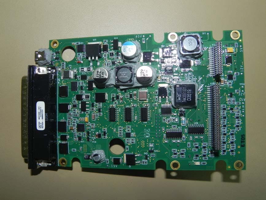
Click to zoom
Application Details
- Equipment Class
- SRT - Radar Transponder
- Date of Grant
- Dec 03, 2014
- Application Purpose
- Original Equipment
- Date of Application
- Oct 01, 2014
- Equipment Note
- Multi Link Transponder
- Frequency Range
- 1030.00000000 - 1030.00000000
- Country
- United States
Documents & Files
Document Text
Text extracted from the exhibit documents filed with the FCC. Open a document above to read the original.
Users Manual
0040-17011-01 (Revision A) Prel-2014 LYNX TM Multilink Surveillance System NGT-2 000/2500 Part Number 9022500-10000 Installation Manual This manual contains installation instructions and recommended flightline maintenance information for the NGT-2 000/2500 Multilink Surveillance System and Configuration Module. Guidelines for external equipment necessary for installation are included. This information is supplemented and kept current by revisions, service letters and service bulletins. DRAFT 3-2 Page A 0040-17011-01 Prel-2014 Revision A Foreword This manual provides information intended for use by persons who, in accordance with current regulatory requirements, are qualified to install this equipment. Installation requirements may vary, depending on the particularities of each aircraft, and this manual is intended as a guideline for that purpose. This manual assumes familiarity with the setup and operation of the aircraft systems that interface with the NGT- 2000/2500. If further information is required, please contact: L- 3 Avionics Systems Attn: Field Service Engineering 5353 52 nd Street, S.E. Grand Rapids, MI USA 49512-9704 Telephone: (800) 453-0288 or (616) 949-6600 Fax: (616) 977-6898 We welcome your comments concerning this manual. Although every effort has been made to keep it free of errors, some may occur. When reporting a specific problem, please describe it briefly and include the manual part number, the paragraph/figure/table number, and the page number. Send your comments to: L- 3 Avionics Systems Attn: Technical Publications 5353 52 nd Street, S.E. Grand Rapids, MI USA 49512-9704 Telephone: (800) 453-0288 or (616) 949-6600 Fax: (616) 977-6898 WARNING INFORMATION SUBJECT TO EXPORT CONTROL LAWS This technical data is controlled under the Export Administration Regulations (EAR) and may not be exported without proper authorization by the U.S. Department of Commerce. Copyright 2014 L- 3 Avionics Systems Trademarks Lynx TM is a trademark of L-3 Avionics Systems Patent Pending DRAFT 3-2 NGT-2000/2500 Installation Manual 0040-17011-01 Page i Revision A Prel-2014 ABOUT THIS MANUAL SECTION 1 – GENERAL INFORMATION This section provides the following information: unit configurations, unit functionality, items required but not supplied with the unit, equipment specifications, installation approval/limitations and TSO approvals. SECTION 2 - INSTALLATION This section contains instructions to locate, assemble and install the NGT-2000/2500 as well as information for unpacking equipment, and inspection procedure for in-shipment damage. SECTION 3 – INSTALLATION CHECKOUT This section contains instructions for post installation setup, post installation and return to service checkout. SECTION 4 – MAINTENANCE This section contains general flightline maintenance procedures. It includes periodic maintenance, troubleshooting and instructions for the return of defective components. APPENDIX A – SIGNAL AND CABLE CHARACTERISTICS This appendix defines the electrical characteristics of all input and output signals. APPENDIX B – ENVIRONMENTAL QUALIFICATION FORM This appendix provides the environmental qualification test data. Descriptions for Warnings, Cautions and Notes described below. WARNING Used to give notice to or call one's attention to beforehand especially of danger (such as a warning to a Flight Crew person or a warning to a mechanic before performing a dangerous task). CAUTION Statement that expresses the need for heightened awareness to conditions that can cause damage to equipment. NOTE Used to point out a procedure, event or practice that it is desirable to highlight. DRAFT 3-2 NGT-2000/2500 Installation Manual Page ii 0040-17011-01 Prel-2014 Revision A References Publication Description 0040-17010-01 Pilot's Guide for the NGT-2000/2500 0040-17020-01 Pilots guide for the CP-2500 Control Panel 0040-17021-01 Installation Manual for the CP-2500 Control Panel DRAFT 3-2 NGT-2000/2500 Installation Manual 0040-17011-01 Page iii Revision A Prel-2014 List of Effective Pages Dates of original and changed pages are: Revision A...................................... Prel-2014 Total number of pages in this publication consists of the following: Title page A Page i thru x 1-1 thru 1-22 2-1 thru 2-20 3-1 thru 3-20 4-1 thru 4-12 A-1 thru A-22 B-1 thru B-2 Disclaimer Information in this manual is subject to change without notice and will not be updated after distribution. Changes to this manual will be reflected in the next revision. Revisions replace the entire manual and are incorporated as needed in order to keep information accurate and up-to-date. Avionics Systems does provide a listing of all publications and directives with their current revision to insure up-to-date information. See www.as.l-3com.com to get an up-to-date listing of all Avionics Systems technical publications and directives. Contact Avionics Systems Customer Care [1-616-949- 6600] to determine availability of technical publications and directives. DRAFT 3-2 NGT-2000/2500 Installation Manual Page iv 0040-17011-01 Prel-2014 Revision A Table of Contents Paragraph Page Foreword ....................................................................................................................................................... A About This Manual ......................................................................................................................................... i References ..................................................................................................................................................... ii List of Effective Pages ................................................................................................................................... iii Table of Contents .......................................................................................................................................... iv List of Illustrations ........................................................…
Text truncated - open the document above for the full version.
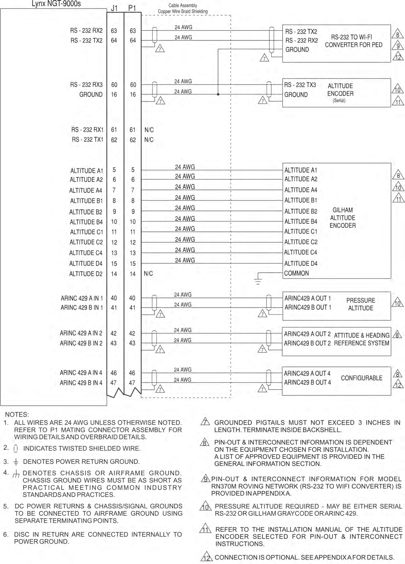
Block Diagram
0040-17011-01 (Revision A) Prel-2014 LYNX TM Multilink Surveillance System NGT-2 000/2500 Part Number 9022500-10000 Installation Manual This manual contains installation instructions and recommended flightline maintenance information for the NGT-2 000/2500 Multilink Surveillance System and Configuration Module. Guidelines for external equipment necessary for installation are included. This information is supplemented and kept current by revisions, service letters and service bulletins. DRAFT 3-2 Page A 0040-17011-01 Prel-2014 Revision A Foreword This manual provides information intended for use by persons who, in accordance with current regulatory requirements, are qualified to install this equipment. Installation requirements may vary, depending on the particularities of each aircraft, and this manual is intended as a guideline for that purpose. This manual assumes familiarity with the setup and operation of the aircraft systems that interface with the NGT- 2000/2500. If further information is required, please contact: L- 3 Avionics Systems Attn: Field Service Engineering 5353 52 nd Street, S.E. Grand Rapids, MI USA 49512-9704 Telephone: (800) 453-0288 or (616) 949-6600 Fax: (616) 977-6898 We welcome your comments concerning this manual. Although every effort has been made to keep it free of errors, some may occur. When reporting a specific problem, please describe it briefly and include the manual part number, the paragraph/figure/table number, and the page number. Send your comments to: L- 3 Avionics Systems Attn: Technical Publications 5353 52 nd Street, S.E. Grand Rapids, MI USA 49512-9704 Telephone: (800) 453-0288 or (616) 949-6600 Fax: (616) 977-6898 WARNING INFORMATION SUBJECT TO EXPORT CONTROL LAWS This technical data is controlled under the Export Administration Regulations (EAR) and may not be exported without proper authorization by the U.S. Department of Commerce. Copyright 2014 L- 3 Avionics Systems Trademarks Lynx TM is a trademark of L-3 Avionics Systems Patent Pending DRAFT 3-2 NGT-2000/2500 Installation Manual 0040-17011-01 Page i Revision A Prel-2014 ABOUT THIS MANUAL SECTION 1 – GENERAL INFORMATION This section provides the following information: unit configurations, unit functionality, items required but not supplied with the unit, equipment specifications, installation approval/limitations and TSO approvals. SECTION 2 - INSTALLATION This section contains instructions to locate, assemble and install the NGT-2000/2500 as well as information for unpacking equipment, and inspection procedure for in-shipment damage. SECTION 3 – INSTALLATION CHECKOUT This section contains instructions for post installation setup, post installation and return to service checkout. SECTION 4 – MAINTENANCE This section contains general flightline maintenance procedures. It includes periodic maintenance, troubleshooting and instructions for the return of defective components. APPENDIX A – SIGNAL AND CABLE CHARACTERISTICS This appendix defines the electrical characteristics of all input and output signals. APPENDIX B – ENVIRONMENTAL QUALIFICATION FORM This appendix provides the environmental qualification test data. Descriptions for Warnings, Cautions and Notes described below. WARNING Used to give notice to or call one's attention to beforehand especially of danger (such as a warning to a Flight Crew person or a warning to a mechanic before performing a dangerous task). CAUTION Statement that expresses the need for heightened awareness to conditions that can cause damage to equipment. NOTE Used to point out a procedure, event or practice that it is desirable to highlight. DRAFT 3-2 NGT-2000/2500 Installation Manual Page ii 0040-17011-01 Prel-2014 Revision A References Publication Description 0040-17010-01 Pilot's Guide for the NGT-2000/2500 0040-17020-01 Pilots guide for the CP-2500 Control Panel 0040-17021-01 Installation Manual for the CP-2500 Control Panel DRAFT 3-2 NGT-2000/2500 Installation Manual 0040-17011-01 Page iii Revision A Prel-2014 List of Effective Pages Dates of original and changed pages are: Revision A...................................... Prel-2014 Total number of pages in this publication consists of the following: Title page A Page i thru x 1-1 thru 1-22 2-1 thru 2-20 3-1 thru 3-20 4-1 thru 4-12 A-1 thru A-22 B-1 thru B-2 Disclaimer Information in this manual is subject to change without notice and will not be updated after distribution. Changes to this manual will be reflected in the next revision. Revisions replace the entire manual and are incorporated as needed in order to keep information accurate and up-to-date. Avionics Systems does provide a listing of all publications and directives with their current revision to insure up-to-date information. See www.as.l-3com.com to get an up-to-date listing of all Avionics Systems technical publications and directives. Contact Avionics Systems Customer Care [1-616-949- 6600] to determine availability of technical publications and directives. DRAFT 3-2 NGT-2000/2500 Installation Manual Page iv 0040-17011-01 Prel-2014 Revision A Table of Contents Paragraph Page Foreword ....................................................................................................................................................... A About This Manual ......................................................................................................................................... i References ..................................................................................................................................................... ii List of Effective Pages ................................................................................................................................... iii Table of Contents .......................................................................................................................................... iv List of Illustrations ........................................................…
Text truncated - open the document above for the full version.
External Photos
Aviation Communication and Surveillance Systems NGT-2500 FCC COMPLIANCE PLAN AND RESULTS CAGE Code 1WYD3 Initial Release Date 01-Oct-2014 Revision Date N/A Document Number 8021005-001 Revision - Proprietary Notice This document and the information disclosed herein are proprietary data of Aviation Communication & Surveillance Systems, LLC. Neither this document nor the information contained herein shall be reproduced, used, or disclosed to others without the written authorization of Aviation Communication & Surveillance Systems, LLC. Notice Freedom of Information Act (5 USC 552) and Disclosure of Confidential Information Generally (18 USC 1905) This document is being furnished in confidence by Aviation Communication & Surveillance Systems, LLC. The information disclosed herein falls within exemption (b) (4) of 5 USC 552 and the prohibitions of 18 USC 1905. Export Notice This technical data is controlled under the Export Administration Regulations (EAR) and may not be exported to a Foreign Person, either in the U.S. or abroad, without proper authorization by the U.S. Department of Commerce. Copyright 2014 Aviation Communication & Surveillance Systems, LLC. All Rights Reserved. Document Number 8021005-001 NGT-2500 FCC Compliance Test Plan and Results Revision - Record of Revisions Rev Date Authorization Description of Change - 01-Oct-2014 ECR015419 Initial Release ACSS Proprietary Use or disclosure of the information on this sheet is subject to the proprietary notice on the title page. RR-1 Document Number 8021005-001 NGT-2500 FCC Compliance Test Plan and Results Revision - Table of Contents 1 INTRODUCTION ................................................................................................................................... 1 1.1 Purpose .......................................................................................................................................... 1 1.2 Scope .............................................................................................................................................. 1 1.3 References ..................................................................................................................................... 1 1.4 Acronyms and Abbreviations .......................................................................................................... 3 2 GENERAL INFORMATION ................................................................................................................... 5 2.1 Type Designation ............................................................................................................................ 5 2.2 Service and Rule for Intended Operation ....................................................................................... 5 2.3 Description of Equipment ............................................................................................................... 5 2.3.1 NGT-2500 Functionality ............................................................................................................ 5 2.3.1.1 Type of Emission ............................................................................................................... 5 2.3.1.2 Frequency Range .............................................................................................................. 5 2.3.1.3 Power Rating ..................................................................................................................... 5 2.3.1.4 Final Power Amplifier ........................................................................................................ 5 2.3.1.5 Active Device Functions .................................................................................................... 6 2.3.2 Circuit Diagram .......................................................................................................................... 6 2.3.3 Instruction Book......................................................................................................................... 6 2.3.4 Tune-up Procedure ................................................................................................................... 6 2.3.5 Oscillator Circuit ........................................................................................................................ 6 2.3.6 LO Source Circuitry ................................................................................................................... 6 2.3.7 Frequency Stabilization ............................................................................................................. 7 2.3.8 Modulation Limiting ................................................................................................................... 7 2.3.9 Radiated Interference Suppression........................................................................................... 7 3 MODULATION DETAILS ....................................................................................................................... 8 3.1 UAT Transmission .......................................................................................................................... 8 3.2 Mode A Interrogation ...................................................................................................................... 8 4 EQUIPMENT AND SETUP .................................................................................................................... 9 4.1 Test Equipment ............................................................................................................................... 9 4.1.1 Setup Block Diagram ................................................................................................................ 9 4.2 LRU Setup ...................................................................................................................................... 9 4.2.1 Hardware Configuration ..................................................…
Text truncated - open the document above for the full version.
ID Label/Location Info
NOTES :1 THIS DEVICE IS SUBJECT T O DAMAGE BY ELECTROSTATIC CHARGES. 4. 2 APPLY ITEM 2 TO ITEM 1 APPROXIMATE LOCATION SHOWN, PER ITEM 701. SEE SEPARATE PARTS LIST 3 TEST PER ITEM 702. 015413 APPLY ITEM 6 TO ITEM 1 APPROXIMATELY AS SHOWN, PER ITEM 701. ADDED FLAG NOTE 4 06-OCT- 2014 IMPROVEMENTS 22-JU LY-2014 UPDATED TABLE AND DRAFTING I/9 C B 015302 REVISIONS ECR NO REV ZONE DESCRIPTION 014656 - INITIAL RELEASE 20-SEP-2013 014765 A THIS SHEET NOT AFFECTED 06-NOV- 2013 PRODUCTION END ITEM OPERATIONAL SOFTWARE / FIRMWARE CONFIGURATION TABLE PART NUMBER 9022500-10000 DEFAULT SOFTWARE LOAD BOOT LOADER 9121105-001 9121110-001 ABROAD, WITHOUT THE PROPER AUTHORIZATION BY THE PROPRIETARY NOTICE TOLERANCES PROJECTION 4 5 6 7 8 9 10 11 12 AB CD EFG H I J K L M 12 11 10 9 8 7 6 5 4 3 2 1 M L K J I H G F ED END ITEM U.S. DEPARTMENT OF COMMERCE FREEDOM OF INFORMATION ACT (5 USC 552) AND THIRD ANGLE (4) OF 5 USC 552 AND THE PROHIBITIONS OF 18 USC 190 5. ASME Y14.5-2009 C 1 19810 North 7th AvenueSurveillance Systems Aviation Communication & DISCLOSURE OF CONFIDENTIAL INFORMATION GENERALLY or disclosed to others without the written authoriz ation of Aviation Communication 9022500-10000 C (18 USC 1905) Neither this document nor the information contained herein shall be reproduced, used, & Thales Company 9022500-10000 END ITEM NEXT ASSY SHEET 1 OF 2 CAGE CODE : 1WYD3 APPLICATION DRAWING NO REV THIS DOCUMENT IS BEING FURNISHED IN CONFIDENCE BY A CSS, LLC data of Aviation Communication & Surveillance Syste ms, LLC. An L-3 Communications TITLE THE INFORMATION DISCLOSED HEREIN FALLS WITHIN EXEMP TION (b) This document and the information disclosed herein are proprietary UNLESS OTHERWISE SPECIFIED, DIMENSIONS ARE IN mm. INTERPRET Phoenix, Arizona 85027-4400 A B 3 2 DIMENSIONS AND TOLERANCES PER NOTICE EXPORT NOTICE (EAR) THIS TECHNICAL DATA IS CONTROLLED UNDER THE EXPORT. ADMINISTRATION REGULATIONS (EAR) AND MAY NOT BEEXPORTED TO A FOREIGN PERSON, EITHER IN THE U.S. OR ASSEMBLY, NGT-2000/2500 9022500-10000 REVISIONS ECR NO REV ZONE DESCRIPTION 014656 - INITIAL RELEASE 20-SEP-2013 014765 A H/3 REMOVE INCORRECT ARROW 06-NOV-2 013 015302 B VAR DRAFTING IMPROVEMENTS 22-JU LY-2014 015413 C J/11 J/11 F/3 DELETE FLAG NOTE 2 DELETE ITEM 2 ADD ISOMETRIC VIEW 06-OCT-2 014 4 5 6 7 8 9 10 11 12 AB CD EFG H I J K L M 12 11 10 9 8 7 6 5 4 3 2 1 M L K J I H G F EDC A B 3 2 1 USE OR DISCLOSURE OF INFORMATION ON THIS SHEET IS SUBJECT TO THE RESTRICTION ON THE FIRST SHEET OF THIS DOCUMENT An L-3 Communications & Thales Company C REV SHEET 2 OF 2 CAGE CODE : 1WYD3 DRAWING NO 9022500-10000 1 1 4. 2.
ID Label/Location Info
5. FOR ALL PART NUMBERS USE BRADY MATERIAL : WHITE POLYSTER (B-483) 1 . ENTER DATE OF MANUFACTURE IN LOCATION SHOWN IN FO RMAT MM/YYYY. 4 ADHESIVE BACKED. . SERIAL NO :THE APPLIANCE ARTICLE SHALL BE MARKED WITH A UNIQUE SERIAL NUMBER NOTES - UNLESS OTHERWISE SPECIFIED 3. 2. REVISIONS ECR NO REV ZONE DESCRIPTION 014656 - INITIAL RELEASE 20-SEP-2013 015046 015047 A F/9 H/7 REMOVED SW MOD INFO UPDATED TSO INFO 07-APR -2014 015187 B UPDATED LABEL REMOVED NOTES 2 AND 3 ADDED NOTE 5 23- JULY-2014 015455 C H/7 ADD FCC ID 06-OCT-2014 1 4 3.00 ±.05 2.00 ±.05 FREEDOM OF INFORMATION ACT (5 USC 552) AND THIRD ANGLE (4) OF 5 USC 552 AND THE PROHIBITIONS OF 18 USC 190 5. PROPRIETARY NOTICE PROJECTION 4 5 6 7 8 9 10 11 12 AB CD EFG H I J K L M 12 11 10 9 8 7 6 5 4 3 2 1 M L K J I H G F E U.S. DEPARTMENT OF COMMERCE 9022500-10000 C This document and the information disclosed herein are proprietary UNLESS OTHERWISE SPECIFIED, DIMENSIONS D 2 DIMENSIONS AND TOLERANCES PER ASME Y14.5-2009 Aviation Communication & DISCLOSURE OF CONFIDENTIAL INFORMATION GENERALLY or disclosed to others without the written authoriz ation of Aviation Communication Surveillance Systems (18 USC 1905) Neither this document nor the information contained herein shall be reproduced, used, & Thales Company 9022502-001 NGT-2000/2500 End Item Label Drawing END ITEM NEXT ASSY SHEET : 1 OF 1 CAGE CODE : 1WYD3 APPLICATION C 19810 North 7th Avenue THIS DOCUMENT IS BEING FURNISHED IN CONFIDENCE BY A CSS, LLC REV DRAWING NO 1 THE INFORMATION DISCLOSED HEREIN FALLS WITHIN EXEMP TION (b) TITLE An L-3 Communications data of Aviation Communication & Surveillance Syste ms, LLC. ARE IN INCHES. INTERPRET Phoenix, Arizona 85027-4400 A B 3 NOTICE EXPORT NOTICE (EAR) THIS TECHNICAL DATA IS CONTROLLED UNDER THE EXPORT. ADMINISTRATION REGULATIONS (EAR) AND MAY NOT BEEXPORTED TO A FOREIGN PERSON, EITHER IN THE U.S. OR ABROAD, WITHOUT THE PROPER AUTHORIZATION BY THE 9022500-10000
Operational Description
0040-17011-01 (Revision A) Prel-2014 LYNX TM Multilink Surveillance System NGT-2 000/2500 Part Number 9022500-10000 Installation Manual This manual contains installation instructions and recommended flightline maintenance information for the NGT-2 000/2500 Multilink Surveillance System and Configuration Module. Guidelines for external equipment necessary for installation are included. This information is supplemented and kept current by revisions, service letters and service bulletins. DRAFT 3-2 Page A 0040-17011-01 Prel-2014 Revision A Foreword This manual provides information intended for use by persons who, in accordance with current regulatory requirements, are qualified to install this equipment. Installation requirements may vary, depending on the particularities of each aircraft, and this manual is intended as a guideline for that purpose. This manual assumes familiarity with the setup and operation of the aircraft systems that interface with the NGT- 2000/2500. If further information is required, please contact: L- 3 Avionics Systems Attn: Field Service Engineering 5353 52 nd Street, S.E. Grand Rapids, MI USA 49512-9704 Telephone: (800) 453-0288 or (616) 949-6600 Fax: (616) 977-6898 We welcome your comments concerning this manual. Although every effort has been made to keep it free of errors, some may occur. When reporting a specific problem, please describe it briefly and include the manual part number, the paragraph/figure/table number, and the page number. Send your comments to: L- 3 Avionics Systems Attn: Technical Publications 5353 52 nd Street, S.E. Grand Rapids, MI USA 49512-9704 Telephone: (800) 453-0288 or (616) 949-6600 Fax: (616) 977-6898 WARNING INFORMATION SUBJECT TO EXPORT CONTROL LAWS This technical data is controlled under the Export Administration Regulations (EAR) and may not be exported without proper authorization by the U.S. Department of Commerce. Copyright 2014 L- 3 Avionics Systems Trademarks Lynx TM is a trademark of L-3 Avionics Systems Patent Pending DRAFT 3-2 NGT-2000/2500 Installation Manual 0040-17011-01 Page i Revision A Prel-2014 ABOUT THIS MANUAL SECTION 1 – GENERAL INFORMATION This section provides the following information: unit configurations, unit functionality, items required but not supplied with the unit, equipment specifications, installation approval/limitations and TSO approvals. SECTION 2 - INSTALLATION This section contains instructions to locate, assemble and install the NGT-2000/2500 as well as information for unpacking equipment, and inspection procedure for in-shipment damage. SECTION 3 – INSTALLATION CHECKOUT This section contains instructions for post installation setup, post installation and return to service checkout. SECTION 4 – MAINTENANCE This section contains general flightline maintenance procedures. It includes periodic maintenance, troubleshooting and instructions for the return of defective components. APPENDIX A – SIGNAL AND CABLE CHARACTERISTICS This appendix defines the electrical characteristics of all input and output signals. APPENDIX B – ENVIRONMENTAL QUALIFICATION FORM This appendix provides the environmental qualification test data. Descriptions for Warnings, Cautions and Notes described below. WARNING Used to give notice to or call one's attention to beforehand especially of danger (such as a warning to a Flight Crew person or a warning to a mechanic before performing a dangerous task). CAUTION Statement that expresses the need for heightened awareness to conditions that can cause damage to equipment. NOTE Used to point out a procedure, event or practice that it is desirable to highlight. DRAFT 3-2 NGT-2000/2500 Installation Manual Page ii 0040-17011-01 Prel-2014 Revision A References Publication Description 0040-17010-01 Pilot's Guide for the NGT-2000/2500 0040-17020-01 Pilots guide for the CP-2500 Control Panel 0040-17021-01 Installation Manual for the CP-2500 Control Panel DRAFT 3-2 NGT-2000/2500 Installation Manual 0040-17011-01 Page iii Revision A Prel-2014 List of Effective Pages Dates of original and changed pages are: Revision A...................................... Prel-2014 Total number of pages in this publication consists of the following: Title page A Page i thru x 1-1 thru 1-22 2-1 thru 2-20 3-1 thru 3-20 4-1 thru 4-12 A-1 thru A-22 B-1 thru B-2 Disclaimer Information in this manual is subject to change without notice and will not be updated after distribution. Changes to this manual will be reflected in the next revision. Revisions replace the entire manual and are incorporated as needed in order to keep information accurate and up-to-date. Avionics Systems does provide a listing of all publications and directives with their current revision to insure up-to-date information. See www.as.l-3com.com to get an up-to-date listing of all Avionics Systems technical publications and directives. Contact Avionics Systems Customer Care [1-616-949- 6600] to determine availability of technical publications and directives. DRAFT 3-2 NGT-2000/2500 Installation Manual Page iv 0040-17011-01 Prel-2014 Revision A Table of Contents Paragraph Page Foreword ....................................................................................................................................................... A About This Manual ......................................................................................................................................... i References ..................................................................................................................................................... ii List of Effective Pages ................................................................................................................................... iii Table of Contents .......................................................................................................................................... iv List of Illustrations ........................................................…
Text truncated - open the document above for the full version.
Test Report
Aviation Communication and Surveillance Systems NGT-2500 FCC COMPLIANCE PLAN AND RESULTS CAGE Code 1WYD3 Initial Release Date 01-Oct-2014 Revision Date N/A Document Number 8021005-001 Revision - Proprietary Notice This document and the information disclosed herein are proprietary data of Aviation Communication & Surveillance Systems, LLC. Neither this document nor the information contained herein shall be reproduced, used, or disclosed to others without the written authorization of Aviation Communication & Surveillance Systems, LLC. Notice Freedom of Information Act (5 USC 552) and Disclosure of Confidential Information Generally (18 USC 1905) This document is being furnished in confidence by Aviation Communication & Surveillance Systems, LLC. The information disclosed herein falls within exemption (b) (4) of 5 USC 552 and the prohibitions of 18 USC 1905. Export Notice This technical data is controlled under the Export Administration Regulations (EAR) and may not be exported to a Foreign Person, either in the U.S. or abroad, without proper authorization by the U.S. Department of Commerce. Copyright 2014 Aviation Communication & Surveillance Systems, LLC. All Rights Reserved. Document Number 8021005-001 NGT-2500 FCC Compliance Test Plan and Results Revision - Record of Revisions Rev Date Authorization Description of Change - 01-Oct-2014 ECR015419 Initial Release ACSS Proprietary Use or disclosure of the information on this sheet i…
Text truncated - open the document above for the full version.
Contact Information
Applicant
John Soukup(Certification Engineer)
Technical Specifications
| # | Rule Parts | Frequency Range | Power Output | Emission | Tolerance |
|---|---|---|---|---|---|
| 2 | 87 | 1.03 GHz - 1.03 GHz | 320.00 µW | 18M0P1D | 19560 Hz |
Other Applications from Aviation Communications and Surveillance Systems (ACSS), LLC.
2ACTZMSS90
Apr 09, 2015Multi Link Transponder
Equipment Class
SRT - Radar Transponder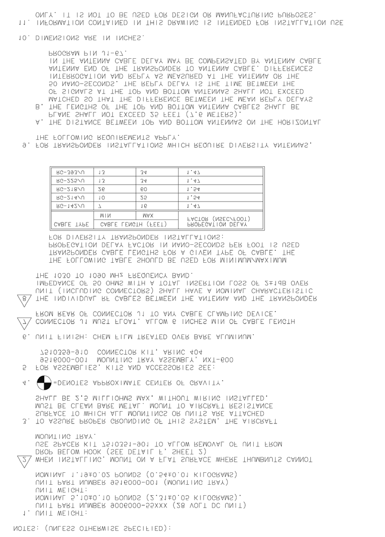
2ACTZNXTXPONDER
Oct 09, 2014ATCRBS/Mode S Transponder
Equipment Class
SRT - Radar Transponder