2ACUJR4269K-Band Doppler Sensor Module (Movement Sensor)
Nisshinbo Micro Devices Inc.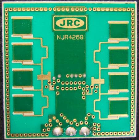
Click to zoom
Application Details
- Equipment Class
- FDS - Part 15 Field Disturbance Sensor
- Date of Grant
- Aug 31, 2015
- Application Purpose
- Original Equipment
- Date of Application
- Aug 31, 2015
- Equipment Note
- K-Band Doppler Sensor Module (Movement Sensor)
- Frequency Range
- 24125.00000000 - 24125.00000000
- Company
- Nisshinbo Micro Devices Inc.
- Country
- Japan
Documents & Files
Document Text
Text extracted from the exhibit documents filed with the FCC. Open a document above to read the original.
Users Manual
1 Rev.01_Jul.8,2015_NJR4269 K-Band Doppler Sensor Module RF Frequency: 24.075 to 24.175 GHz Model No. NJR4269F3V1/F3V2 Voltage Line-up: V1: 5V Vcc V2: 3V/3.3V Vcc Specifications Rev.01 July 8, 2015 Copyright 2015 New Japan Radio Co., Ltd. Microwave Components Division -Notice of Proprietary Information- This documents and its contents are proprietary to New Japan Radio Co., Ltd. This publication and its contents may not be reproduced or distributed for any other purpose without the written permission of New Japan Radio Co., Ltd. * Above Specifications are subject to change without notice. 2 Rev.01_Jul.8,2015_NJR4269 Caution 1. NJRC strives to produce reliable and high quality microwave components. NJRC's microwave components are intended for specific applications and require proper maintenance and handling. To enhance the performance and service of NJRC's microwave components, the devices, machinery or equipment into which they are integrated should undergo preventative maintenance and inspection at regularly scheduled intervals. Failure to properly maintain equipment and machinery incorporating these products can result in catastrophic system failures. 2. To ensure the highest levels of reliability, NJRC products must always be properly handled. The introduction of external contaminants (e.g. dust, oil or cosmetics) can result in failures of microwave components. 3. NJRC offers a variety of microwave components intended for particular applications. It is important that you select the proper component for your intended application. You may contact NJRC's sales office or sales representatives, if you are uncertain about the products listed in the catalog and the specification sheets. 4. Special care is required in designing devices, machinery or equipment, which demand high levels of reliability. This is particularly important when designing critical components or systems whose foreseeable failure can result in situations that could adversely affect health or safety. In designing such critical devices, equipment or machinery, careful consideration should be given to, amongst other things, their safety design, fail-safe design, back-up and redundancy systems, and diffusion design. 5. The products listed in the catalog and specification sheets may not be appropriate for use in certain equipment where reliability is critical or where the products may be subjected to extreme conditions. You should consult our sales office or sales representatives before using the products in any of the following types of equipment. * Aerospace Equipment * Equipment Used in the Deep Sea * Power Generator Control Equipment (nuclear, steam, hydraulic) * Life Maintenance Medical Equipment * Fire Alarm/Intruder Detector * Vehicle Control Equipment (automobile, airplane, railroad, ship, etc.) * Various Safety Equipment 6. NJRC's products have been designed and tested to function within controlled environmental conditions. Do not use products under conditions that deviate from methods or applications specified in the catalog and specification sheets. Failure to employ NJRC's products in the proper applications can lead to deterioration, destruction or failure of the products. NJRC shall not be responsible for any bodily injury, fires or accidents, property damage or any consequential damages resulting from the misuse or misapplication of its products. PRODUCTS ARE SOLD WITHOUT WARRANTY OF ANY OF KIND, EITHER EXPRESS OR IMPLIED, INCLUDING BUT NOT LIMITED TO ANY IMPLIED WARRANTY OF MERCHANTABILITY OR FITNESS FOR A PARTICULAR PURPOSE. 7. The product specifications and descriptions listed in the catalog and specification sheets are subject to change at any time, without notice. * Above Specifications are subject to change without notice. 3 Rev.01_Jul.8,2015_NJR4269 1. Electric Characteristics (Common measure condition Ta= +25 ºC) Item Specification Unit Condition / Note Min. Typ. Max. 1.1 Operation Voltage V1 type (Vcc = 5V) 4.75 - 5.25 V Refer to Remarks V2 type (Vcc = 3V/3.3V) 2.95 - 3.35 V Refer to Remarks 1.2 Operation Current V1 type (Vcc = 5V) - 30 40 mA Vcc = 5 V V2 type (Vcc = 3V/3.3V) - 30 40 mA Vcc = 3 V - 35 45 mA Vcc = 3.3 V 1.3 Operation Frequency Ta= -20 to +60 ºC 24.075 - 24.175 GHz 1.4 E.I.R.P. - +16 - dBm 1.5 Frequency Stability - -0.4 - MHz/ºC Ta= -20 to +60 ºC 1.6 Start-up Time - 20 - usec Pulse Condition: Duty 0.5% min. 1.7 2nd Harmonics (E.I.R.P.) - - -30 dBm 1.8 Radiation Pattern - - - - 1.8.1 –3dB Beam Width (H-plane) - 76 - deg. Refer to Figure 1 1.8.2 –3dB Beam Width (V-plane) - 37 - deg. 1.8.3 Side-lobe Suppression (H-plane) - - - dB No side lobe 1.8.4 Side-lobe Suppression (V-plane) - 13 - dB 1.9 IF Output Offset Voltage -300 - +300 mV 1.10 IF Output Signal Level 250 450 - mVp-p Refer to Figure 2 : Signal Test System Amp. Gain: 29 dB 1.11 IF Noise Output Voltage - 200 - mVp-p Test Setup: Amp. Gain: 86 dB Amp. Band Width: 10 to 300 Hz Remarks: DC power supply for each module should be conformed to the electrical specifications as descr ibed in this section. A host in which a module is integrated should provide stable DC power through suitable regulator circuit to the module. * Above Specifications are subject to change without notice. 4 Rev.01_Jul.8,2015_NJR4269 Figure 1 Typical Radiation Pattern 2. Mechanical characteristics Item Specification 2.1 Size 25(W) x 25(D) x 6.8(H) mm Tolerance: ±0.3 mm 2.2 Weight 7 g max. 2.3 Interface / Pin assignment Pin Size: 0.64 mm square Pin Pitch: 2.54 mm Recommended via hole diameter: 1.2 ± 0.05 mm 20100-10-20 90 60 30 0 -30 -60 -90 (dBm) Angle (deg.) 20100-10-20 90 60 30 0 -30 -60 -90 (dBm) Angle (deg.) V - P lane H-Plane H-plane 76 degree V-plane 37 degree * Above Specifications are subject to change without notice. 5 Rev.01_Jul.8,2015_NJR4269 3. Environmental characteristics Item Specification 3.1 Operation Temperature -20 to +60 ºC 3.2 Storage Temperature -40 to +80 ºC 3.3 Humidity 0 to 95 % @ +30 ºC 3.4 Vibration 49.03 m/s 2 (5 G) 30 to 50 Hz, 10 minute…
Text truncated - open the document above for the full version.
External Photos
13 7. External Photos Diagrammatic perspective view Front side Back side: Patch Antenna
ID Label/Location Info
12 6. Label *NJR4262F3V1 *NJR4262F3V2 Material: PET Adhesive compound: PA-T1 (acrylic ester) Life time: over 10years
Internal Photos
14 8. Internal Photo With Shield cover Without Shield cover
RF Exposure Info
FCC ID: 2ACUJR4269 Produkte Products RF Exposure Statement: 50031017 002 Page 1 of 1 Client: New Japan Radio Co., Ltd. 1-1, Fukuoka 2-Chome, Fujimino City Saitama, 356-8510 Japan Test item: K-Band Doppler Sensor Module (Movement Sensor) Identification: NJR4269F3V1, NJR4269F3V2 FCC Requirement According to the FCC 2.1093, portable equipment must comply with the following applicable limit for maximum permissible exposure (MPE) specified in FCC 1.1310: Equipment Use Frequency Range Power Density [mW/cm 2 ] Average Time [min] General Population / Uncontrolled Exposure 1.5 – 100GHz 1.0 30 Note: According to the FCC 2.1093 (d), this evaluation was conducted at 5cm distance. Measurement Result The maximum measured transmitter power is given in the following table: Measured E-Field Strength [dBuV/m] Meas. Distance [m] Evaluated Distance [cm] Distance Correction Factor [dB] Calculated E-Field Strength E (at 5cm) Calculated Power Density S [mW/cm 2 ] [dBuV/m] [V/m] 109.5 3 5 35.6 145.1 18.0 0.086 Note: Distance Correction Factor = 20 × Log 10 (3 / 0.05) = 35.6 dB The power density S in mW/cm 2 is calculated according to the next formula: S = E 2 / 3770, Where E = electric field strength in V/m Conclusion The EUT is categorized as portable device specified by the customer. SAR evaluation is NOT required since the transmitter frequency is higher than 6GHz (i.e. 24.125GHz as nominal). Therefore, this evaluation was performed by the calculations. As a result, Calculated Power Density S is below the FCC thresholds at 5cm distance. For details, refer to the test report 50031017 001, especially section 5.2 Radiated measurement. TÜV Rheinland Japan Ltd. – Global Technology Assessment Center 4-25-2 Kita-Yamata, Tsuzuki-ku, Yokohama 224-0021, Japan
Test Report
FCC ID: 2ACUJR4269 Produkte Products Prüfbericht - Nr.: Test Report No.: 50031017 001 Seite 2 von 30 Page 2 of 30 TEST SUMMARY 5.1.1 SUPPLY VOLTAGE REQUIREMENTS RESULT: PASS 5.1.2 ANTENNA REQUIREMENTS RESULT: PASS 5.1.3 RESTRICTED BANDS OF OPERATION RESULT: PASS 5.2.1 RADIATED EMISSIONS OF TRANSMITTER (CARRIER, SPURIOUS AND HARMONICS) RESULT: PASS 5.2.2 20DB BANDWIDTH RESULT: PASS 5.3.1 AC POWER LINE CONDUCTED EMISSION OF TRANSMITTER RESULT: PASS FCC ID: 2ACUJR4269 Produkte Products Prüfbericht - Nr.: Test Report No.: 50031017 001 Seite 3 von 30 Page 3 of 30 Contents 1. GENERAL REMARKS ............................................................................................... 4 1.1 COMPLEMENTARY MATERIALS ................................................................................. 4 2. TEST SITES ............................................................................................................ 4 2.1 TEST FACILITIES ..................................................................................................... 4 2.2 LIST OF TEST AND MEASUREMENT INSTRUMENTS ...................................................... 5 2.3 MEASUREMENT UNCERTAINTY ................................................................................. 7 3. GENERAL PRODUCT INFORMATION ........................................................................... 8 3.1 PRODUCT FUNCTION AND INTENDED USE .................................................................. 8 3.2 SYSTEM DETAILS .................................................................................................... 8 3.3 CLOCK FREQUENCIES ............................................................................................. 9 3.4 NOISE SUPPRESSING PARTS .................................................................................... 9 4. TEST SET-UP AND OPERATION MODES ................................................................... 10 4.1 TEST METHODOLOGY ............................................................................................ 10 4.2 OPERATION MODES .............................................................................................. 10 4.3 PHYSICAL CONFIGURATION FOR TESTING ............................................................... 10 4.4 TEST SOFTWARE .................................................................................................. 11 4.5 SPECIAL ACCESSORIES AND AUXILIARY EQUIPMENT ............................................... 11 4.6 COUNTERMEASURES TO ACHIEVE EMC COMPLIANCE .............................................. 12 5. TEST RESULTS R ADI O ....................................................................................... 13 5.1 TECHNICAL REQUIREMENTS ................................................................................... 13 5.1.1 Supply Voltage Requirements ................................................................................................... 13 5.1.2 Antenna Requirements .............................................................................................................. 13 5.1.3 Restricted Bands of Operation ................................................................................................... 14 5.2 RADIATED MEASUREMENTS ................................................................................... 15 5.2.1 Radiated Emissions of Transmitter (Carrier, Spurious and Harmonics) .................................... 15 5.2.2 20dB Bandwidth ......................................................................................................................... 21 5.3 AC POWER LINE CONDUCTED MEASUREMENTS ...................................................... 23 5.3.1 AC Power Line Conducted Emission of Transmitter .................................................................. 23 6. PHOTOGRAPHS OF THE TEST SETUP....................................................................... 26 7. LIST OF TABLES .................................................................................................... 30 8. LIST OF FIGURES .................................................................................................. 30 9. LIST OF PHOTOGRAPHS ......................................................................................... 30 FCC ID: 2ACUJR4269 Produkte Products Prüfbericht - Nr.: Test Report No.: 50031017 001 Seite 4 von 30 Page 4 of 30 1. General Remarks 1.1 Complementary Materials There is no attachment to this test report. 2. Test Sites 2.1 Test Facilities TÜV Rheinland Japan Ltd. – Global Technology Assessment Center 4-25-2 Kita-Yamata, Tsuzuki-ku, Yokohama 224-0021, Japan The used test equipment is in accordance with CISPR 16 for measurement of radio interference. The Federal Communications Commission has reviewed the technical characteristics of the radiated and conducted emission facilities and has found these test sites to be in compliance with the requirements of section 2.948 of the FCC rules. The description of the test facility is listed under FCC registration number 299054. The test facility is accredited by VLAC (member of ILAC) under number VLAC-017 according to ISO/IEC 17025:2005. TÜV Rheinland Japan Ltd. is accredited by the Federal Communications Commission as a Conformity Assessment Body under Designation Number JP0017 and Test Firm Registration Number 386498. FCC ID: 2ACUJR4269 Produkte Products Prüfbericht - Nr.: Test Report No.: 50031017 001 Seite 5 von 30 Page 5 of 30 2.2 List of Test and Measurement Instruments Table 1: List of Test and Measurement Equipment Kind of Equipment Manufacturer Model Name Serial Number Equipment ID Calibrated until For AC Power Line Conducted Emission Conducted Emission Measurement Software Toyo Corporation EP5/CE Ver. 5.0.20 RF-0025 2016-01 Receiver Rohde & Schwarz ESU 40 100029 RF-0021 2016-03 LISN Rohde & Schwarz ENV216 100276 RF-0016 2016-05 For Radiated Emission Radiated Emission Measurement Soft- ware (below 30MHz) Toyo Corporat…
Text truncated - open the document above for the full version.
Test Setup Photos
FCC ID: 2ACUJR4269 Produkte Products Prüfbericht - Nr.: Test Report No.: 50031017 001 Seite 26 von 30 Page 26 of 30 6. Photographs of the Test Setup Photograph 1: Set-up for AC Power Line Conducted Emission of Transmitter, Front View Photograph 2: Set-up for AC Power Line Conducted Emission of Transmitter, Rear View FCC ID: 2ACUJR4269 Produkte Products Prüfbericht - Nr.: Test Report No.: 50031017 001 Seite 27 von 30 Page 27 of 30 Photograph 3: Set-up for Radiated Emission of Transmitter, Front View Photograph 4: Set-up for Radiated Emission of Transmitter, MMW General View FCC ID: 2ACUJR4269 Produkte Products Prüfbericht - Nr.: Test Report No.: 50031017 001 Seite 28 von 30 Page 28 of 30 Photograph 5: Set-up for Radiated Emission, EUT Configuration X-Axis Photograph 6: Set-up for Radiated Emission, EUT Configuration Y-Axis FCC ID: 2ACUJR4269 Produkte Products Prüfbericht - Nr.: Test Report No.: 50031017 001 Seite 29 von 30 Page 29 of 30 Photograph 7: Set-up for Radiated Emission, EUT Configuration Z-Axis
Contact Information
Applicant
Yuji Kita(QA General Manager)
Technical Contact
TUV Rheinland Japan Ltd.Akira Abe
[email protected]+81459140242
Global Technology Assessment Center · Yokohama · Japan
Test Firm
TUV Rheinland Japan Ltd.Thimo Sauter
Technical Specifications
| # | Rule Parts | Frequency Range | Power Output |
|---|---|---|---|
| 1 | 15.245 | 24.13 GHz - 24.13 GHz | - |
Other Applications from Nisshinbo Micro Devices Inc.
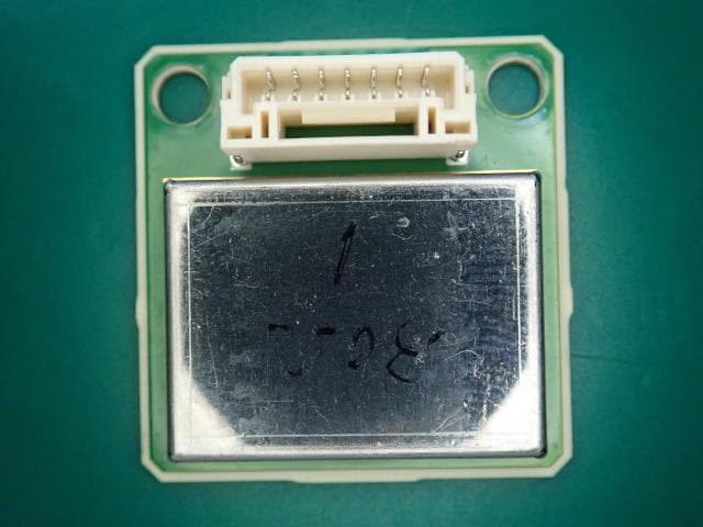
2ACUJR4274
Feb 17, 2022K-Band Doppler Sensing Device (Movement Sensor)
Equipment Class
DXX - Part 15 Low Power Communication Device Transmitter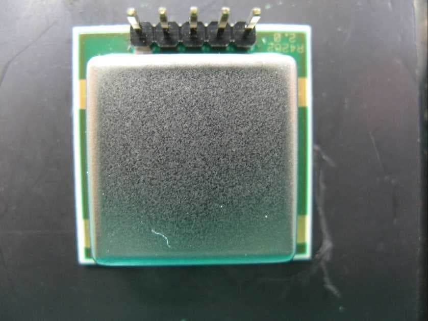
2ACUJR4262
Jan 19, 2015K-Band Doppler Sensor Module (Movement Sensor)
Equipment Class
FDS - Part 15 Field Disturbance Sensor