2ACUQ-SR-281Wall mounted DMX512 Master
Shenzhen Sunricher Technology Co.,Ltd
Click to zoom
Application Details
- Equipment Class
- DTS - Digital Transmission System
- Date of Grant
- Jul 30, 2014
- Application Purpose
- Original Equipment
- Date of Application
- Jul 30, 2014
- Equipment Note
- Wall mounted DMX512 Master
- Frequency Range
- 2412.00000000 - 2462.00000000
- Country
- China
Documents & Files
Document Text
Text extracted from the exhibit documents filed with the FCC. Open a document above to read the original.
Users Manual
Wall mounted DMX512 Master Parameter Product Size 1 zone Touch sensitive Suitable for USA market Feature SR-2812Wi(US) Glass interface(White & Black) Save color and mode function Part No. Operation Voltage DIMENSIONS ø/h (mm) OUTPUT SR-2812Wi(US)12VDC 120x75x29.1 WIFI Installation Wiring diagram D-GND LN 110V-230VAC Power Supply 12 VDC GNDD+ SR-2812Wi(US) 120.0 75.0 29.1 Vin Power Supply 12-36VDC L N 110V-230VAC D1 D1 D2 D2 SR-2102B DMX512 Decoder GND white D1 D1 D2 D2 SR-2102B DMX512 Decoder GND white D1 D1 D2 D2 SR-2102B DMX512 Decoder GND white Power Supply 12-36VDC L N 100V-240VAC white SR-1009FA LED CONTROLLER 1 2 3 4 Learning Key white SR-1009FA LED CONTROLLER 1 2 3 4 Learning Key white SR-1009FA LED CONTROLLER 1 2 3 4 Learning Key 3)RF SR-2812(US) with SR-1009XX 1)DMX SR-2812(US) with DMX decoder RF WIFI Operation Play&pause button. There is only 1 build-in mode. When you touch button, it will run. Long press speed up, long press again speed down. Brightness Button can save the three color from mode or save color when you touch color wheel. When you press this button, 1 build-in mode will run, if now you see a favorite mode, then you can press "S" button for 5 seconds until connected lighting flashes. Then it saved successfully. When you touch color wheel, if you touch a favorite color on it, then you want to save it, then you press "S" button for 5 seconds until the connected lighting flashes. Then it saved successfully. For Warm white, Natural white, Cool white changing.(Through the three RGB color mixing) Touching wheels Switch off and on, long press means default setting Short press means switch on and off for each channel. 1st Long press means brightness+, 2nd Long press means brightness—. At the corner of the panel there is a signal light, Blue means on, Red means off Please set the connected DMX Decoders’ address to be 001 only. when SR-2812Wi(US) is used under wireless RF wall mounted dimmer Learning process a. Wake up the panel by touching ON/OFF button. b. Press at learning button on receiver. c.Then touch color wheel. d.Connected LED l ight wi l l bl ink e . Press at learning button on receiver over 5 seconds unti l LED l ight flash, then delete the learned ID. Safety & Warnings Warranty Agreement 1) The product shall be installed and serviced by a qualified person. 2) IP20.Please avoid the sun and rain. When installed outdoors, please ensure it is mounted in a water proof enclosure. 3) Always be sure to mount this unit in an area with proper ventilation to avoid overheating. 4) Please check if the output voltage of any LED power supplies used comply with the working voltage of the product. 5) Never connect any cables while power is on and always assure correct connections to avoid short circuits before switching on. 6) 7) For update information please consult your supplier. Please ensure that the cable is secured tightly in the connector 1) We provide lifelong technical assistance with this product: 3-year warranty. We print date on every products, for example :1125 means year 2011,week 25.The warranty is for free repair or replacement and covers manufacturing faults only. For faults beyond the 3-year warranty we reserve the right to charge for time and parts. 2) Limited Warrenty Any defects caused by wrong operation. Any damages caused by unauthorized removal, maintenance, modifying, incorrect connection and replacement of chips. Any damages due to transportation, vibration etc. after purchase. Any damages caused by earthquake, fire, lightning, pollution and abnormal voltage. Any damages caused by negligence, inappropriate storing at high temperatures and humidity or near harmful chemicals. Product has been updated 3) Repair or replacement as provided under this warranty is the exclusive remedy to the customer. IOS or android system connection to the SR-2812Wi(US) a.Download app to phone. Open wifi connection setting interface,connect your phone to EASYCOLOR or Realcolor network. b.Open EASYCOLOR installed on the phone , press to the setting interface, and enter the following: SSID:EASYCOLOR IP: 10.10.100.254 8899 Name: (the name you want or don’t enter anything.) c.Press button to turn it on ,and press button to back to the main operation interface. Wifi to DMX function the app is 8 zone control, so you may set more zones for the WiFi control as below: DMX decoder’s address 001 is controlled by Zone 1 DMX decoder’s address 005 is controlled by Zone 2 DMX decoder’s address 009 is controlled by Zone 3 DMX decoder’s address 013 is controlled by Zone 4 DMX decoder’s address 017 is controlled by Zone 5 DMX decoder’s address 021 is controlled by Zone 6 DMX decoder’s address 025 is controlled by Zone 7 DMX decoder’s address 029 is controlled by Zone 8 38 FCC Certification Requirements Caution: Any changes or modifications in construction of this device which are not expressly approved by the party responsible for compliance could void the user's authority to operate the equipment. This device complies with part 15 of the FCC Rules. Operation is subject to the following two conditions: (1) This device may not cause harmful interference, and (2) This device must accept any interference received, including interference that may cause undesired operation. The manufacturer is not responsible for any radio or TV interference caused by unauthorized modifications to this equipment. Such modifications could void the user’s authority to operate the equipment. This equipment has been tested and found to comply with the limits for a Class B digital device, pursuant to Part 15 of the FCC Rules. These limits are designed to provide reasonable protection against harmful interference in a residential installation. This equipment generates, uses and can radiate radio frequency energy and, if not installed and used in accordance with the instructions, may cause harmful interference to radio communications. However, there is no guarantee that interference will not occur in a particular instal…
Text truncated - open the document above for the full version.
Cover Letter(s)
Shenzhen Sunricher Technology Co.,Ltd 310,Longtaili building No.30,Avenue 4th,High Tech Sience Park,Shenzhen Confidentiality Request Letter Page 1 of 1 Rev 2.0 July 28, 2014 To: Federal Communications Commission Authorization and Evaluation Division 7435 Oakland Mills Road Columbia, MD Permanent Confidentiality Request Confidentiality Request regarding application for certification of FCC ID: 2ACUQ-SR-281 We hereby request confidential treatment of information accompanying this application as outlined below: - Block Diagram - Operational Description - Schematic The above materials contain trade secrets and proprietary information not customarily released to the public. The public disclosure of these materials may be harmful to the applicant and provide unjustified benefits to its competitors. The applicant understands that pursuant to Section 0.457 & 0.459 of the Rules, disclosure of this application and all accompanying documentation will not be made before the date of the Grant for this application. Sincerely, Client’s signature: Client’s name / title: Zou Lifang/ Manager Contact information / address: 310,Longtaili building No.30,Avenue 4th,High Tech Sience Park,Shenzhen TEL: 0755-86017718 FAX: 0755-26765389 E-mail: [email protected]
Cover Letter(s)
Shenzhen Sunricher Technology Co.,Ltd 310,Longtaili building No.30,Avenue 4th,High Tech Sience Park,Shenzhen Date: July 28, 2014 Subject: Ad Hoc Mode Function Declaration FCC ID: 2ACUQ-SR-281 To Whom it may concern, This device is acting as slave and operating in the 2.4 GHz (2412 – 2462 MHz) band. Ad Hoc function is supported but not able to operate on non-US frequencies. 9.59dBm is the Max Conducted Power Please contact the one signed below or the authorized agent for this filing. Thank you. Regards, Client’s signature: Client’s name / title: Zou Lifang/ Manager Contact information / address: 310,Longtaili building No.30,Avenue 4th,High Tech Sience Park,Shenzhen TEL: 0755-86017718 FAX: 0755-26765389 E-mail: [email protected]
External Photos
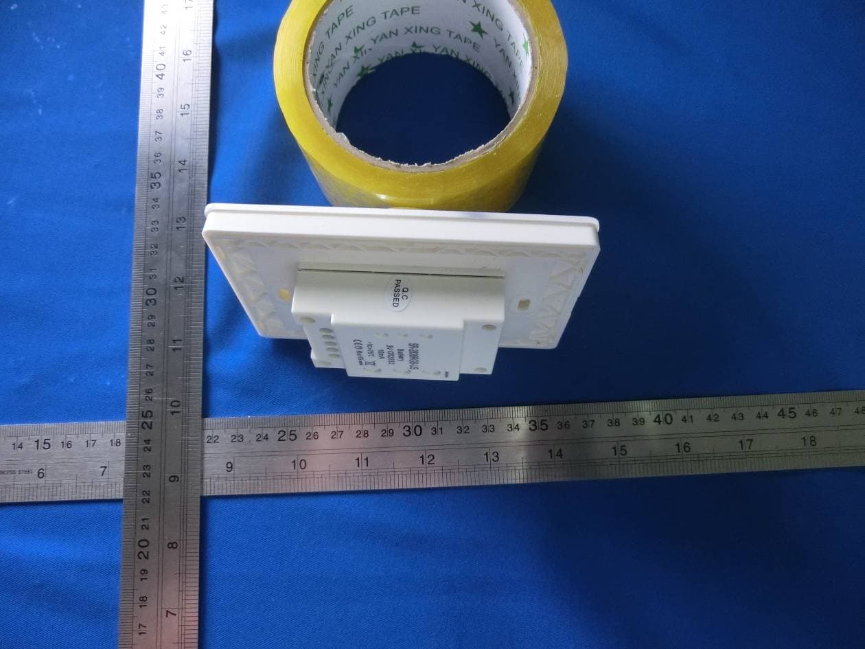
External Photo
ID Label/Location Info
FCC Certification Label FCC ID: 2ACUQ-SR-281 Label Location on EUT label size:high 1cm, Wide:2 cm EUT View/ FCC ID Label Location
Internal Photos
Internal Photo WIFI Antenna
RF Exposure Info
BSL1771011Y-6 1 Maximum Permissible Exposure report For Shenzhen Sunricher Technology Co.,Ltd 310,Longtaili building No.30,Avenue 4th,High Tech Sience Park,Shenzhen FCC ID: 2ACUQ-SR-281 July 28, 2014 This Report Concerns: Original Report Equipment Type: Wall mounted DMX512 Master Test Engineer: Lisa Chen Report No.: BSL1771011Y-6 Receive EUT Date/Test Date: July 09 / July 09 - July 28, 2014 Reviewed By: Sky Zhang Prepared By: BSL Testing Co.,LTD. NO. 24, ZH Park, Nantou, Shenzhen, 518000 China Tel: 86- 755-26508703 Fax: 86- 755-26508703 BSL1771011Y-6 2 1.§ 15.247 (i) and §1.1307 (b) (1) – Maximum Permissible exposure (MPE) 1.1 Standard Applicable According to subpart 15.247 (i) and subpart 1.1307 (b)(1), systems operating under the provisions of this section shall be operated in a manner that ensures the public is not exposed to RF energy level in excess of the communication guidelines. Limits for General Population/Uncontrolled Exposure Frequency Range (MHz) Electric Field Strength (V/m) Magnetic Field Strength (A/m) Power Density (mW/cm 2 ) Averaging Time (minute) Limits for General Population/Uncontrolled Exposure 0.3–3.0 614 1.63 *(100) 30 3.0–30 824/f 2.19/f *(180/f2) 30 30–300 27.5 0.073 0.2 30 300–1500 / / f/1500 30 1500–100,0 00 / / 1.0 30 f = frequency in MHz * = Plane-wave equivalent power density 1.2 Test Data Prediction of MPE limit at a given distance Equation from page 18 of OET Bulletin 65, Edition 97-01 S = PG/4πR² S: Power density, in mW/cm² P: Power input to the antenna, in mW G: numeric gain of the antenna R: distance to the center of the antenna, in cm BSL1771011Y-6 3 802.11b Mode Maximum peak output power at antenna input terminal (dBm): 9.59 Maximum peak output power at antenna input terminal (mW): 9.10 Prediction distance (cm): 20 Prediction frequency (MHz): 2412 Antenna Gain, typical (dBi): 0 Maximum Antenna Gain (numeric): 1 Power density at predication frequency and distance (mW/cm 2 ): 0.0018 MPE limit for Occupational exposure at predication frequency (mW/cm 2 ): 1.0 802.11g Mode Maximum peak output power at antenna input terminal (dBm): 9.13 Maximum peak output power at antenna input terminal (mW): 8.18 Prediction distance (cm): 20 Prediction frequency (MHz): 2412 Antenna Gain, typical (dBi): 0 Maximum Antenna Gain (numeric): 1 Power density at predication frequency and distance (mW/cm 2 ): 0.0016 MPE limit for Occupational exposure at predication frequency (mW/cm 2 ): 1.0 802.11n Mode Maximum peak output power at antenna input terminal (dBm): 9.30 Maximum peak output power at antenna input terminal (mW): 8.51 Prediction distance (cm): 20 Prediction frequency (MHz): 2412 Antenna Gain, typical (dBi): 0 Maximum Antenna Gain (numeric): 1 Power density at predication frequency and distance (mW/cm 2 ): 0.0017 MPE limit for Occupational exposure at predication frequency (mW/cm 2 ): 1.0 1.3 Test Result The device is compliant with the requirement MPE limit of General Population/Uncontrolled Exposure at predication frequency 1.0 mW/cm2 .And the precaution is outlined in the user’s manual to prevent to high level of RF energy.
Test Report
FCC PART 15.247 EMI MEASUREMENT AND TEST REPORT For Shenzhen Sunricher Technology Co.,Ltd 310,Longtaili building No.30,Avenue 4th,High Tech Sience Park,Shenzhen FCC ID: 2ACUQ-SR-281 July 28, 2014 This Report Concerns: Original Report Equipment Type: Wall mounted DMX512 Master Test Engineer: Lisa Chen Report No.: BSL7407101ba Receive EUT Date/Test Date: July 09 / July 09 - July 28, 2014 Reviewed By: Sky Zhang Prepared By: BSL Testing Co.,LTD. NO. 24, ZH Park, Nantou, Shenzhen, 518000 China Tel: 86- 755-26508703 Fax: 86- 755-26508703 Note: The test report is specially limited to the above company and this particular sample only. It may not be duplicated without prior written consent of BSL Testing Co.,LTD. This report must not be used by the client to claim product certification, approval,or endorsement by NVLAP, NIST or any agency of the US Government. FCC ID: 2ACUQ-SR-281 BSL7407101ba Page 2/48 TABLE OF CONTENTS 1. GENERAL INFORMATION ....................................................................................................4 1.1. Report information ............................................................................................................4 1.2. Measurement Uncertainty .................................................................................................4 2. PRODUCT DESCRIPTION ......................................................................................................5 2.1. EUT Description ...............................................................................................................5 2.2. Block Diagram of EUT Configuration..............................................................................6 2.3. Support Equipment List ....................................................................................................6 2.4. Test Conditions .................................................................................................................6 3. TEST RESULTS SUMMARY ...................................................................................................7 Modifications ................................................................................................................................7 4. TEST EQUIPMENT USED .......................................................................................................8 5. §15.203 - ANTENNA REQUIREMENT ...................................................................................9 5.1. Standard Applicable..........................................................................................................9 5.2. Antenna Connector Construction......................................................................................9 5.3. Result ................................................................................................................................9 6. §15.207 - CONDUCTED EMISSIONS....................................................................................10 6.1. Applicable Standard........................................................................................................10 6.2. Test Procedure ................................................................................................................10 6.3. Conducted Power line Emission Limits..........................................................................10 6.4. Block Diagram of Test Setup..........................................................................................10 6.5. Conducted Power Line Test Result.................................................................................11 7. §15.209, §15.205, §15.247(D) - SPURIOUS EMISSIONS .....................................................13 7.1. Test Equipment ...............................................................................................................13 7.2. Test Procedure ................................................................................................................13 7.3. Radiated Test Setup ........................................................................................................13 7.4. Radiated Emission Limit.................................................................................................15 7.5. Radiated Emission Test Result .......................................................................................16 7.6. Conducted Emission Method ..........................................................................................24 7.7. Test Requirement: ...........................................................................................................24 7.8. Limit:...............................................................................................................................24 7.9. Test Setup........................................................................................................................24 7.10. Test Result ......................................................................................................................24 8. §15.247(A) (2) – 6DB BANDWIDTH TESTING....................................................................30 8.1. Test Equipment ...............................................................................................................30 8.2. Test Procedure ................................................................................................................30 8.3. Applicable Standard........................................................................................................30 8.4. Test Result:Pass. .............................................................................................................30 9. §15.247(B) (3) - MAXIMUM PEAK OUTPUT POWER ......................................................36 9.1. Test Equipment ...............................................................................................................36 9.2. Test Procedure ......................................…
Text truncated - open the document above for the full version.
Test Setup Photos
Radiated emissions test Conducted emissions test
Contact Information
Applicant
Zou Lifang(Manager)
Test Firm
BSL Testing Co.,LTD.Boss Deng
Technical Specifications
| # | Rule Parts | Frequency Range | Power Output |
|---|---|---|---|
| 1 | 15C | 2.41 GHz - 2.46 GHz | 9.10 mW |
Other Applications from Shenzhen Sunricher Technology Co.,Ltd
2ACUQ2836
Sep 23, 2015LED Controller
Equipment Class
DSC - Part 15 Security/Remote Control Transmitter
2ACUQPEAK
Jun 17, 2015WIFI LED controller
Equipment Class
DTS - Digital Transmission System