2ACWNZS6284Zonesafe Standard Unit
Avonwood Developments Ltd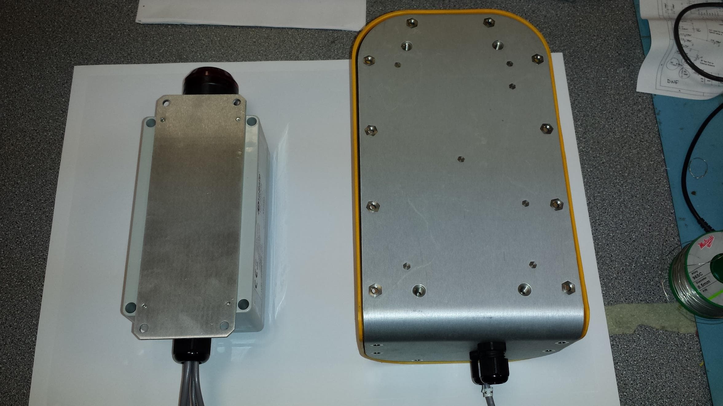
Click to zoom
Application Details
- Equipment Class
- DCD - Part 15 Low Power Transmitter Below 1705 kHz
- Date of Grant
- Oct 05, 2014
- Application Purpose
- Original Equipment
- Date of Application
- Oct 05, 2014
- Equipment Note
- Zonesafe Standard Unit
- Frequency Range
- 0.12500000 - 0.12500000
- Company
- Avonwood Developments Ltd
- Country
- United Kingdom
Documents & Files
Document Text
Text extracted from the exhibit documents filed with the FCC. Open a document above to read the original.
Users Manual
ZoneSafe™ System User Manual ZoneSafe ™ System User Manual Avonwood Developments Limited Knoll Technology Centre, Stapehill Road Wimborne, Dorset, BH21 7ND Tel: +44 (0) 1202 868000 Fax: +44 (0) 1202 868001 Email: [email protected] www.avonwood.co.uk ZoneSafe™ System User Manual A176283 © 2011 Copyright Avonwood Developments Limited Page | 2 Document Name ZoneSafe ™ System User Manual Document Number A176283 Original Issue Date 24/09/2014 Record of Changes Issue No. Date of Issue Detail of Change Information in this document is subject to change without notice. You do not have permission to reproduce, publish or share any part of this document either electronically or printed in part or full without prior written consent from Avonwood Developments Ltd. ZoneSafe™ System User Manual A176283 © 2011 Copyright Avonwood Developments Limited Page | 3 Contents 1 Introduction 5 2 How the System Works 5 3 System Components 6 3.1 Control Unit 6 3.2 Wakeup Antenna Units 6 3.3 Transponder 6 3.4 Driver Transponder 7 3.5 Manager Software 7 3.6 Transponder Test Unit 7 3.7 LED Test Transponder 7 3.8 Fixing Kits 7 4 Hardware Installation 8 5 Example Installation 9 6 Connections 10 7 System Specification 11 7.1 Control Unit 11 7.2 Wakeup Antenna Unit 11 7.3 Transponder 12 7.4 Transponder Test Unit 12 8 WEEE Directive 13 9 FCC Compliance Information 14 10 Disclaimer 15 11 Appendix A – Transponder Test Unit Operation Guide 16 17 ZoneSafe™ System User Manual A176283 © 2011 Copyright Avonwood Developments Limited Page | 4 This page is intentionally blank ZoneSafe™ System User Manual A176283 © 2011 Copyright Avonwood Developments Limited Page | 5 NOTE: Detection accuracy will depend on environmental and installation factors . NOTE: The ZoneSafe™ proximity warning system is supplied as an audible and/or visual alert system only. It is not a protective device, it does not initiate or perform safety related functions and it does not provide control to reduce risk but and audible/visual alert to the operator of the risk. . 1 Introduction ZoneSafe™ is a proximity warning system that produces an invisible detection zone around any machine or area it is fitted to. The system detects transponders worn by personnel or fitted to other objects that are within its proximity and provides an audible/visual warning. ZoneSafe™ systems are supplied as audible and/or visual warning systems, which provide an aid to safety only. ZoneSafe™ should not be used to replace proper job site organisation, safeguards, operator training and the application of relevant vision standards that addresses safety and the safety of people on job sites. 2 How the System Works ZoneSafe™ is based on proven radio frequency technology. The driver of the vehicle places an Authorized driver transponder in to the control unit. Completing this ensures the drivers transponder does not set off the detection alarm. If no Authorized Driver Transponder is placed in the Control Unit a constant alarm will sound. The system produces a user configurable detection zone around a machine or area between 3m to 9m which interacts with transponders worn by personnel or other hazards. When a ZoneSafe™ transponder is within the proximity of, or enters the detection zone of a ZoneSafe™ enabled object, a visual and/or audible indication is provided to the machine operator. The ZoneSafe™ system comprises a control unit with display, antenna units and transponders. Each installed system has its own unique identification code, as do each of the transponders used with the system. The Control Unit can optionally contain an LCD which can indicate the location of the detected transponder in the zone The system’s main control unit has a real time clock and built in memory for storing an audit trail of up to 7000 proximity detection events and system configuration settings. Event logs and system settings can be viewed for each control unit using the ZoneSafe™ software or ZoneSafe Android APP ZoneSafe™ Manager software provides an easy to use interface for downloading, viewing, analysing and exporting event data. ZoneSafe™ System User Manual A176283 © 2011 Copyright Avonwood Developments Limited Page | 6 3 System Components The ZoneSafe™ system comprises the following standard components and accessories (part numbers in Installation and Operation Manual): Standard Components 1. ZoneSafe™ Control Unit 2. ZoneSafe™ Wakeup Antenna Unit(s) 3. ZoneSafe™ Driver Transponders 4. ZoneSafe™ Transponders Accessories 5. ZoneSafe™ Transponder Test Unit 6. ZoneSafe™ LED Test Transponder 7. ZoneSafe™ Fixing Kits 8. ZoneSafe™ Software 9. Discovery Readers 3.1 Control Unit The ZoneSafe™ Control Unit contains the main electronics of the system and requires a 24V DC supply (other voltages available on request). All of the other system devices are connected to and are controlled by the control unit. The control unit contains a real-time clock (with battery backup) for time and date information, internal memory to store event data and a Bluetooth interface for communication. A relay is available for the addition of external sounders or beacons for alerting personnel in the detection zone. Warning indicators and unit features include: Alarm Buzzer/Light o Pulsing -Transponder in Zone o Constant - No Driver Transponder, No ignition or system fault Mute Button o Alarm mute for one transponder when pressed 3.2 Wakeup Antenna Units The ZoneSafe™ Wakeup Antenna Units generate the detection zone around an object. Antennas should be fitted at appropriate locations to provide the optimum detection zone required. Wakeup antenna units are linked together with the first unit connected to the system control unit. The number of antennas required depends on the size of the detection zone and the size of the machine or area they are fitted to. The size of the generated detection zone from each antenna is adjustable from approximately 3m to 9m. 3.3 Transponder All ZoneSafe™ Transponders are worn by all personnel or f…
Text truncated - open the document above for the full version.
Cover Letter(s)
Eureka Radio Frequency Identification Systems t: +44 (0) 1202 868000 www.avonwood.co.uk e: [email protected] Avonwood Developments Limited Knoll Technology Centre, Stapehill Road, Wimborne, Dorset, BH21 7ND Tel: +44 (0) 1202 868000 Fax: +44 (0) 1202 868001 Email: [email protected] Web: www.avonwood.co.uk Avonwood is an ISO 9001:2000 Registered Company & RoSH Compliant Avonwood Developments Limited is registered in England & Wales No. 02570711. Reg. Office: Knoll Technology Centre, Stapehill Road, Wimborne, Dorset, BH21 7ND. Request for Confidentiality Date: 30/09/2014 Subject: Confidentiality Request for: 2ACWNZS6284 Pursuant to FCC 47 CRF 0.457(d) and 0.459 and IC RSP-100, Section 10, the applicant requests that a part of the subject FCC application be held confidential. Type of Confidentiality Requested Exhibit Short Term Permanent Block Diagrams Short Term Permanent Operation Description/Theory of Operation Short Term Permanent Parts List & Placement/BOM Short Term Permanent Schematics Avonwood Developments Ltd has spent substantial effort in developing this product and it is one of the first of its kind in industry. Having the subject information easily available to "competition" would negate the advantage they have achieved by developing this product. Not protecting the details of the design will result in financial hardship. Permanent Confidentiality: The applicant requests the exhibits listed above as permanently confidential be permanently withheld from public review due to materials that contain trade secrets and proprietary information not customarily released to the public. Sincerely, By: Engineering Manager David Stanley-Boden
Cover Letter(s)
Eureka Radio Frequency Identification Systems t: +44 (0) 1202 868000 www.avonwood.co.uk e: [email protected] Avonwood Developments Limited Knoll Technology Centre, Stapehill Road, Wimborne, Dorset, BH21 7ND Tel: +44 (0) 1202 868000 Fax: +44 (0) 1202 868001 Email: [email protected] Web: www.avonwood.co.uk Avonwood is an ISO 9001:2000 Registered Company & RoSH Compliant Avonwood Developments Limited is registered in England & Wales No. 02570711. Reg. Office: Knoll Technology Centre, Stapehill Road, Wimborne, Dorset, BH21 7ND. 03 Oct 14 References: A. EMC Test Report No. 14R307b FR dated 7 Aug 14 – Hursley EMC Services B. FCC Application ID 2ACWNZS6284 Clarification of FCC application 2ACWNZS6284 To whom it may concern, The equipment under test (EUT) specified at reference A has 4 different configurations that are stated in section 2.1 of that document. The tests carried out on this piece of equipment were all conducted with a single antenna attached (EURIDK6083 control and 1 antenna). Due to this, the FCC application is only for the single antenna variant of this system. Yours Sincerely, David Stanley-Boden Engineering Manager
ID Label/Location Info
Zonesafe Compact FCC ID: 2ACWNZS6284 Contains FCC ID: T9J-RN42 This device complies with part 15 of the FCC Rules. Operation is subject to the following two conditions: (1) This device may not cause harmful interference, and (2) This device must accept any interference received, including interference that may cause undesired operation.
ID Label/Location Info
Old Label position New Label position FCC Label Position
Test Report
Hursley EMC Services Ltd. Trafalgar House Trafalgar Close Chandlers Ford, Eastleigh Hampshire. UK. SO53 4BW EMC TEST REPORT No. 14R307b FR Issue#1: 7 th August 2014 UKAS Accredited EU Notified Body FCC & VCCI Registered BSMI Lab ID: SL2-IN-E-3008 KC Lab ID: EU0184 Tel. +44 (0) 23 8027 1111 Fax. +44 (0) 23 8027 1144 e mail. [email protected] www.hursley-emc.co.uk FCC Part 15C Certification Report for the Avonwood Developments Ltd Standard Zone Safe Control Unit and Antenna Project Engineer: R. P. St John James Approval Signatory Approved signatories: S. M. Connolly J. A. Jones The above named are authorised Hursley EMC Services engineers. EMC TEST REPORT 14R307b FR FCC Part 15C Certification Report Issue#1: 7 th August 2014 Page 2 of 14 Contents 1.0 DECLARATION ................................................................................................................................................ 3 1.1 FCC PART 15C STATEMENT.................................................................................................................................. 3 1.2 RELATED SUBMITTAL(S) GRANTS ......................................................................................................................... 3 1.3 EUT MANUFACTURER .......................................................................................................................................... 3 2.0 EUT DESCRIPTION ......................................................................................................................................... 4 2.1 IDENTITY ............................................................................................................................................................... 4 2.2 PRODUCT OPERATION ........................................................................................................................................... 4 2.3 SUPPORT EQUIPMENT ............................................................................................................................................ 4 2.4 EXERCISER PROGRAM ........................................................................................................................................... 4 3.0 MEASUREMENT PROCEDURE AND INSTRUMENTATION ................................................................. 5 3.1 EMI SITE ADDRESS & TEST DATE ........................................................................................................................ 5 3.2 GENERAL OPERATING CONDITIONS ...................................................................................................................... 5 3.3 ENVIRONMENTAL AMBIENT .................................................................................................................................. 5 3.4 RADIATED EMISSIONS ........................................................................................................................................... 6 4.0 TEST DATA ....................................................................................................................................................... 7 4.1 FCC – RADIATED EMISSIONS (RECEIVE MODE) .................................................................................................. 10 5.0 TEST PLOTS.................................................................................................................................................... 10 5.1 RADIATED EMISSION PLOT, 9 KHZ TO 30 MHZ ................................................................................................... 10 5.2 RADIATED EMISSION PLOT, 30 TO 1000 MHZ ..................................................................................................... 11 5.3 RADIATED EMISSIONS PLOT, 0.998 TO 2.9 GHZ .................................................................................................. 12 5.4 RADIATED EMISSIONS PLOT, 2.8 TO 10.0 GHZ .................................................................................................... 13 6.0 RADIATED EMISSIONS PLOTS – RECEIVE MODE .............................................................................. 14 7.0 FCC DETAILS ................................................................................................................................................. 14 EMC TEST REPORT 14R307b FR FCC Part 15C Certification Report Issue#1: 7 th August 2014 Page 3 of 14 1.0 DECLARATION 1.1 FCC Part 15C Statement The Equipment Under Test (EUT), as described and reported within this document, complies with parts 15.109 and 15.209 of the CFR 47:2013 FCC rules in accordance with ANSI C63.4:2003. The EUT operates at frequencies of 902.4 MHz and complies with part 15C emission requirements. 1.2 Related Submittal(s) Grants This is an application for certification of an Avonwood Standard Zone Safe Control Unit and Antenna (transmitting at 125kHz and receiving at 902.4 MHz), described in this report. The sections of FCC Part 15 that apply to the EUT are: 15.209 General requirements 15.109 applied to the EUT in receive mode. Note: The EUT in receiver mode complies with part 15B of the FCC rules for unintentional radiators. 1.3 EUT Manufacturer Trade name: Avonwood Developments Ltd Company name: Avonwood Developments Ltd Company address: Knoll Technology Centre Stapehill Road Hampreston Wimborne Dorset BH21 7ND United Kingdom Manufacturing address: As above. Company representative: Mr Martin Hoyle Tel: +44 (0) 1202 868000 EMC TEST REPORT 14R307b FR FCC Part 15C Certification Report Issue#1: 7 th August 2014 Page 4 of 14 2.0 EUT DESCRIPTION 2.1 Identity EUT: Standard Zone Safe Control Unit and Antenna Model: K = kit EURIDK6083 control and 1 antenna K = kit EURIDK6059 control and 2 antenna K = kit EURIDK6085 control and 3 antenna K = kit EURIDK6025 control and 4 antenna Containing: Control unit: EURIDI6089 Large Wakeup unit: EURIDW6068 Serial numbers: Control unit: 22969 Large Wakeup unit: 23508 Sample build:…
Text truncated - open the document above for the full version.
Test Setup Photos
Hursley EMC Services Ltd. Trafalgar House Trafalgar Close Chandlers Ford, Eastleigh Hampshire. UK. SO53 4BW EMC TEST REPORT No. 14R307b FRA Tel. +44 (0) 23 8027 1111 Fax. +44 (0) 23 8027 1144 e mail. [email protected] www.hursley-emc.co.uk UKAS Accredited EU Notified Body FCC & VCCI Registered BSMI Lab ID: SL2-IN-E-3008 KC Lab ID: EU0184 Photo Log for the Avonwood Developments Ltd Standard Zone Safe Control Unit and Antenna EMC TEST REPORT 14R307b FRA FCC Part 15C Certification Report Page 2 of 8 1.0 PHOTO LOG Emissions: Radiated emissions, 9 kHz to 30 MHz OATS 10m EMC TEST REPORT 14R307b FRA FCC Part 15C Certification Report Page 3 of 8 Photo Log (continued) Oats Scan 3m EMC TEST REPORT 14R307b FRA FCC Part 15C Certification Report Page 4 of 8 Photo Log (continued) Radiated emissions, Oats 30 MHz to 1 GHz EMC TEST REPORT 14R307b FRA FCC Part 15C Certification Report Page 5 of 8 Photo Log (continued) Radiated emissions, Oats 30 MHz to 1 GHz EMC TEST REPORT 14R307b FRA FCC Part 15C Certification Report Page 6 of 8 Photo Log (continued) Radiated emissions, Oats 1 GHz to 10 GHz EMC TEST REPORT 14R307b FRA FCC Part 15C Certification Report Page 7 of 8 Photo Log (continued) EUT Close up EMC TEST REPORT 14R307b FRA FCC Part 15C Certification Report Page 8 of 8 Photo Log (continued)
Contact Information
Applicant
David Thomas
Technical Contact
Non-Technical Contact
Avonwood Developments LtdDavid Thomas
Test Firm
Eurofins Hursley LtdAndrew Coombes
Technical Specifications
| # | Rule Parts | Frequency Range | Power Output |
|---|---|---|---|
| 1 | 15C | 0.125 MHz - 0.125 MHz | - |
Other Applications from Avonwood Developments Ltd
2ACWNZS6277
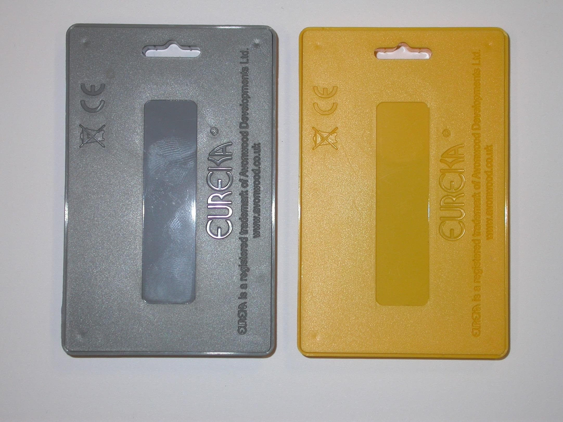
Sep 29, 2014Transponder Tag
Equipment Class
DXX - Part 15 Low Power Communication Device Transmitter