2ACXB872737ARemote Lock
Snap-on Incorporated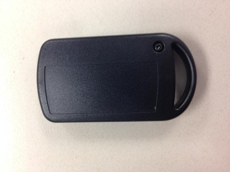
Click to zoom
Application Details
- Equipment Class
- DSR - Part 15 Remote Control/Security Device Transceiver
- Date of Grant
- Sep 29, 2014
- Application Purpose
- Original Equipment
- Date of Application
- Sep 29, 2014
- Equipment Note
- Remote Lock
- Frequency Range
- 433.90000000 - 433.90000000
- Company
- Snap-on Incorporated
- Country
- United States
Documents & Files
Document Text
Text extracted from the exhibit documents filed with the FCC. Open a document above to read the original.
Users Manual
1 Remote Lock Owner’s Manual 2 IMPORTANT SAFETY INSTRUCTIONS This document contains important safety and operation instructions for tool storage units equipped with remote lock. Refer to this information often for safe usage and operation. SAVE THESE INSTRUCTIONS WARNING Improper usage can cause broken parts. Read instructions before usage. Broken parts can cause injury. Units can tip or strike you. Do not open more than one loaded drawer at a time Close lid and lock drawers before moving Apply brakes on locking casters when not moving Do not step in or on drawers Secure units together with fasteners Disconnect or unplug all power cords and cable assemblies before moving unit Read instruction manual Tipping of storage unit or unit striking you can cause injury Component edges can cut or pinch. Keep fingers clear of edges when working near or with sheet metal components Keep hands and fingers clear of sharp objects Units’ edges or components can cause injury WARNING Risk of tripping. Do not place power adapter in walkway Disconnect or unplug all power cords and cable assemblies before moving unit Tripping can cause injury Risk of electric shock and fire. Do not remove the ground connection Do not expose to rain, snow, or wet conditions Do not operate with damaged cord or plug Replace damaged cord or plug immediately Do not expose remote’s lithium battery to fire or very high temperatures Electric shock or fire can cause injury 3 IMPORTANT SAFETY INSTRUCTIONS con’t This document contains important safety and operation instructions for tool storage units equipped with remote lock. Refer to this information often for safe usage and operation. SAVE THESE INSTRUCTIONS WARNING Risk of explosion. Flammable fuel or vapors can ignite This equipment should not be lo cated in a recessed area or below floor level Remote lock has internal arcing or sparking parts Do not expose to flammable vapors. Explosion or flame can cause injury Risk of shock or injury. Remote lock service must be performed only by a Snap-on Representative Service or maintenance performe d by a person other than a Snap- on Representative ma y result in injury When servicing remote lock, use only identical replacement parts. Follow instructions in the maintenance section of this manual. Use of unauthorized parts or fa ilure to follow maintenance instructions may result in shock or injury. GROUNDING INSTRUCTIONS This product must be grounded. If it shoul d malfunction or break down, grounding provides a path of least resistance for elec tric current to reduce the risk of electric shock. This product is equipped with a cord having an equipment-grounding conductor and a grounding plug. The plug must be plugged into an appropriate outlet that is properly installed and grounded in accordance with all local codes and ordinances. WARNING Risk of electric shock and fire. Do not remove the ground connection Electric shock or fire can cause injury Improper connection of the equipment-grounding conductor is able to result in a risk of electric shock. Check with a qualified el ectrician or serviceman if you are in doubt as to whether the product is properly grounded. Do not modify the plug provided with the product – if it will not fit the outlet, have a proper outlet installed by a qualified electrician. 4 FCC Notice FCC ID: Fob/Transmitter 2ACXB872737A IC: 12245A-872737A This device complies with part 15 of the FCC rules. Operation is subject to the following two conditions: (1) This device may not cause harmful interference; and (2) This device must accept any interference received, including interference that may cause undesired operation. Le présent appareil est conforme aux CNR d’Industrie Canada applicables aux appareils radio exempts de licence. L’expl oitation est autorisée aux deux conditions suivantes: (1) l’appareil ne doit pas produire de brouillage, et (2) l’utilisateur de l’appareil doit accepter tout brouillage radioél ectrique subi, même si le brouillage est susceptible d’en compromettre le fonctionnement. Note: This equipment has been tested and found to comply with the limits for a Class B digital device, pursuant to part 15 of the FCC Rules. These limits are designed to provide reasonable protection against harmful interference in a residential installation. This equipment generates, us es, and can radiate radio frequency energy and, if not installed and used in accordance with the instructions, may cause harmful interference to radio communications. However, there is no guarantee that interference will not occur in a particular installation. If this equipment does cause harmful interference to radio or televisi on reception, which can be determined by turning the equipment off and on, the user is encouraged to try to correct the interference by one or more of the following measures: o Reorient or relocate the receiving antennae o Increase the separation between the equipment and receiver o Connect the equipment into an output or circuit different from that to which the receiver is connected o Consult the dealer or an experienced radio/TV technician for help 5 Table of Contents IMPORTANT SAFETY INSTRUCTIONS ............................... 2 FCC Notice ................................................................................. 4 Table of Contents ....................................................................... 5 Features ...................................................................................... 6 Specifications ............................................................................. 6 Remote.................................................................................... 6 Power .................................................................................. 6 Battery Life......................................................................... 6 Storage ................................................................................ 6 Remote Lo…
Text truncated - open the document above for the full version.
Cover Letter(s)
Tool Storage August 5, 2014 Subject: Confidentiality Request for: FCC ID: 2ACXB872737A Pursuant to FCC 47 CRF 0.457(d) and 0.459 and IC RSP-100, Section 10, the applicant requests that a part of the subject FCC application be held confidential. Type of Confidentiality Requested Exhibit Permanent Block Diagrams Permanent Operation Description/Theory of Operation Permanent Parts List & Placement/BOM Permanent Tune-Up Procedure Permanent Schematics Snap-on Incorporated has spent substantial effort in developing this product and it is one of the first of its kind in industry. Having the subject information easily available to “competition” would negate the advantage they have achieved by developing the product. Not protecting the details of the design will result in financial hardship. Permanent Confidentiality: The applicant requests the exhibits listed above as permanently confidential be permanently withheld from public review due to materials that contain trade secrets and proprietary information not being customarily released to the public. NOTE for Industry Canada Applications: The applicant understands that until such time that IC distinguishes between Short Term and Permanent Confidentiality, either type of marked exhibit above will simply be marked Confidential when submitted to IC. Sincerely, By: __________________________ _______________________________ Snap-on Incorporated P.O. Box 1410 Kenosha, WI 53141-1431 262-656-5200
Test Report
Engineering Test Report No. 1402783-01 Measurement of RF Emissions from a Model 8-73737A-6 Transmitter For Snap On Tools 2801 80th Street Kenosha, WI 53143 P.O. Number 130-1YC002125 Date Tested July 10 through 24, 2014 Test Personnel Dan Crowder Test Specification FCC "Code of Federal Regulations” Title 47 Part15, Subpart C Industry Canada RSS-GEN Industry Canada RSS-210 Test Report By: Dan Crowder Requested By: Matthew Crass Snap On Tools Approved By: Raymond J. Klouda Registered Professional Engineer of Illinois - 44894 Elite Electronic Engineering, Inc. 1516 Centre Circle Downers Grove, IL 60515 Tel : (630) 495-9770 Fax: (630) 495-9785 www.elitetest.com Engineering Test Report No. 1402783-01 TABLE OF CONTENTS PARAGRAPH DESCRIPTION OF CONTENTS PAGE NO. THIS REPORT SHALL NOT BE REPRODUCED, EXCEPT IN FULL, WITHOUT THE WRITTEN APPROVAL OF ELITE ELECTRONIC ENGINEERING INCORPORATED. Page 2 of 25 1. Introduction ................................................................................................................................................... 5 1.1. Scope of Tests ..................................................................................................................................... 5 1.2. Purpose ............................................................................................................................................... 5 1.3. Deviations, Additions and Exclusions .................................................................................................. 5 1.4. EMC Laboratory Identification ............................................................................................................. 5 1.5. Laboratory Conditions.......................................................................................................................... 5 2. Applicable Documents .................................................................................................................................. 5 3. EUT Setup and Operation ............................................................................................................................ 5 3.1. General Description ............................................................................................................................. 5 3.1.1. Power Input ................................................................................................................................. 6 3.1.2. Peripheral Equipment ................................................................................................................. 6 3.1.3. Signal Input/Output Leads .......................................................................................................... 6 3.1.4. Grounding ................................................................................................................................... 6 3.2. Software ............................................................................................................................................... 6 3.3. Operational Mode ................................................................................................................................ 6 3.4. EUT Modifications ................................................................................................................................ 6 4. Test Facility and Test Instrumentation ......................................................................................................... 6 4.1. Shielded Enclosure .............................................................................................................................. 6 4.2. Test Instrumentation ............................................................................................................................ 6 4.3. Calibration Traceability ........................................................................................................................ 6 4.4. Measurement Uncertainty ................................................................................................................... 6 5. Test Procedures ........................................................................................................................................... 7 5.1. Powerline Conducted Emissions ......................................................................................................... 7 5.1.1. Requirements .............................................................................................................................. 7 5.2. Periodic Operation Measurements ...................................................................................................... 7 5.2.1. Requirements .............................................................................................................................. 7 5.2.2. Procedures .................................................................................................................................. 7 5.2.3. Results ........................................................................................................................................ 7 5.3. Duty Cycle Factor Measurements ....................................................................................................... 7 5.3.1. Procedures .................................................................................................................................. 7 5.3.2. Results ........................................................................................................................................ 8 5.4. Radiated Measurements ..................................................................................................................... 8 5.4.1. Requirements .............................................................................................................................. 8 5.4.2. Procedures .......................................................................................…
Text truncated - open the document above for the full version.
Test Setup Photos
Engineering Test Report No. 1402783-01 Page 15 of 25 Figure 3 Test Setup for Radiated Emissions, 30MHz to 1GHz – Horizontal Polarization Test Setup for Radiated Emissions, 30MHz to 1GHz – Vertical Polarization Engineering Test Report No. 1402783-01 Page 16 of 25 Figure 4 Test Setup for Radiated Emissions, 1GHz to 5GHz – Horizontal Polarization Test Setup for Radiated Emissions, 1GHz to 5GHz – Vertical Polarization
Contact Information
Applicant
Rodger Isetts(Product Manager)
Technical Contact
Creative WerksBob Folkestad
[email protected]5156455902
1434 E. Fleming Ave. · Des Moines, Iowa · United States
Test Firm
Elite Electronic Engineering Inc.Kevin Halpin
Technical Specifications
| # | Rule Parts | Frequency Range | Power Output |
|---|---|---|---|
| 1 | 15.231 | 433.9 MHz - 433.9 MHz | - |
Other Applications from Snap-on Incorporated
2ACXBECFLPRA0
Apr 12, 2020Wireless Charge Base
Equipment Class
DCD - Part 15 Low Power Transmitter Below 1705 kHz
2ACXBCTBTSP861
Mar 15, 2020BLUETOOTH SPEAKER
Equipment Class
DSS - Part 15 Spread Spectrum Transmitter