2ACXBECFLPRA0Wireless Charge Base
Snap-on Incorporated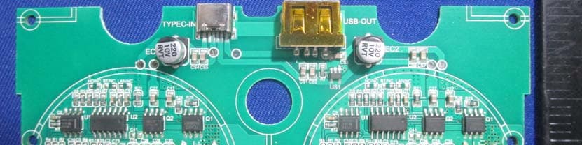
Click to zoom
Application Details
- Equipment Class
- DCD - Part 15 Low Power Transmitter Below 1705 kHz
- Date of Grant
- Apr 12, 2020
- Application Purpose
- Original Equipment
- Date of Application
- Apr 12, 2020
- Equipment Note
- Wireless Charge Base
- Frequency Range
- 0.11000000 - 0.20500000
- Company
- Snap-on Incorporated
- Country
- United States
Documents & Files
Document Text
Text extracted from the exhibit documents filed with the FCC. Open a document above to read the original.
Users Manual
This equipment should be installed and operated with minimum distance 15cm between Wireless Charge Base ECFLPRA0 ECFLPRA0 Base de carga inalámbrica Product Details: ■ Wireless dynamic charging system allow partial recharging. ■ Only work with Snap-on wireless lamps and accessories. ■ Recharge using the bi-directional USB-C connection. ■ Equipped with built-in magnets. ■ Charge external devices with built-in USB charging port, output: DC5V 1A. ■ Pack delivered with 5V 3.5A charger, Input: AC100-240V, Output: DC5V 3.5A Product Description: Descripción del producto Replacement Parts: ■ ECFLPRA0-7 - 5V 3.5A USB-C Charger Warranty/Service: ■ 1 year warranty covering defects in material and workmanship ■ For service, please send to the appropriate repair center below Western Repair Center (USA) 3602 Challenger Way Carson City, NV 89706-0753 USA Toll Free # - USA only: (888) 762-7972 Telephone: (775) 883-8585 Fax: (775) 883-8590 Northern Repair Center (USA) 3011 E. RT 176, Dock 8 Crystal Lake, IL 60014 USA Toll Free # - USA only: (877) 777-4412 Telephone: (815) 479-6850 Fax: (815) 479-6857 Eastern Repair Center (USA) 6320 Flank Dr. Harrisburg, PA 17112 USA Toll Free # - USA only: (800) 848-5067 Telephone: (717) 652-7914 Fax: (717) 652-7123 ■ ECFLPRA0-7 - 5V 3.5A Cargador USB -C Datos del producto: ■ El sistema de carga dinámica inalámbrico permite la recarga parcial. ■ Funciona solamente con lámparas y accesorios inalámbricos Snap-on. ■ Recárguela con la conexión USB-C bidireccional. ■ Equipado con imanes integrados. ■ Cargue dispositivos externos con el puerto de carga USB incorporado, Salida: 5Vcc 1A ■ El paquete incluye cargador USB-C de 5V 3.5A; Entrada: 100-240Vca; Salida: 5Vcc 3.5A Made in China Snap-on and wrench "S" are trademarks of Snap-on Incorporated. ©2019 Snap-on Incorporated. Printed in China Snap-on, 2801 80th St., Kenosha, WI 53143 www.snapon.com Hecho en China Snap-on y la Wrench “S” son marcas registradas de Snap-on Incorporated. ©2019 Snap-on Incorporated. Impreso en China Snap-on, 2801 80th St., Kenosha, WI 53143 www.snapon.com ■ Do not use the wireless charging base near open flames. ■ Do not charge the wireless smartphones. Piezas de remplazo: Garantía/ Servicio: ■ 1 año de garantía que cubre defectos en materiales y mano deobra ■ Para el servicio, por favor envíe al centro de reparación adecuada a continuación Centro de Reparación del Oeste (EE.UU.) 3602 Challenger Way Ciudad de Carson, NV 89706-0753 EE.UU. Teléfono Gratuito # - sólo EE.UU. (888) 762-7972 Teléfono: (775) 883-8585 Fax: (775) 883-8590 Centro de Reparación del Este (EE.UU.) 6320 Flank Dr. Harrisburg, PA 17112 EE.UU. Teléfono Gratuito # - sólo EE.UU. (800) 848-5067 Teléfono: (717) 652-7914 Fax: (717) 652-7123 Centro de Reparación del Norte (EE.UU.) 3011 E. RT 176, Dock 8 Crystal Lake, IL 60014 EE.UU. Teléfono Gratuito # - sólo EE.UU. (877) 777-4412 Teléfono: (815) 479-6850 Fax: (815) 479-6857 ■ No uses la base de carga inalámbrica cerca de llamas abiertas. ■ No cargue los smartphones inalámbricos. . Charge Magnet Magnet Bolt hole Input Output Port Carga Imán Imán Orificio para perno Entrad Puerto de salida FCC Warning Any Changes or modifications not expressly approved by the party responsible for compliance could void the user's authority to operate the equipment. This device complies with part 15 of the FCC Rules. Operation is subject to the following two conditions: (1) This device may not cause harmful interference, and (2) this device must accept any interference received, including interference that may cause undesired operation. Note: This equipment has been tested and found to comply with the limits for a Class B digital device, pursuant to part 15 of the FCC Rules. These limits are designed to provide reasonable protection against harmful interference in a residential installation. This equipment generates, uses and can radiate radio frequency energy and, if not installed and used in accordance with the instructions, may cause harmful interference to radio communications. However, there is no guarantee that interference will not occur in a particular installation. If this equipment does cause harmful interference to radio or television reception, which can be determined by turning the equipment off and on, the user is encouraged to try to correct the interference by one or more of the following measures: —Reorient or relocate the receiving antenna. —Increase the separation between the equipment and receiver. —Connect the equipment into an outlet on a circuit different from that to which the receiver is connected. —Consult the dealer or an experienced radio/TV technician for help. FCC Radiation Exposure Statement the radiator& your body. This transmitter must not be co-located or operating in conjunction with any other antenna or transmitter. ■ Le système de chargement dynamiquesans fil permet un rechargement partiel. ■ Ne fonctionne qu'avec des lampes sans fil et des accessoires Snap-on. ■ Rechargez en utilisant la connexion USB-C bidirectionnelle. ■ Équipé d’aimant intégrés. ■ Chargez des appareils externes avec un port de chargement USB intégré, sortie : DC5V 1A ■ Paquet livré avec un chargeur USB-C 5V 3.5A ; Entrée : AC100 - 240V ; Sortie : DC5V 3.5A ECFLPRA0 Base de charge sans fil Piéces de remplacement : Garantie/Service: ■ Garantie de 1 année couvrant les défauts de matériaux et de fabrication ■ Pour le service, veuillez envoyez au centre de réparation approprié ci-dessous Centre de Réparation Ouest (États-Unis) 3602 Challenger Way Carson City, NV 89706-0753 États-Unis Numéro Sans Frais # - États-Unis seulement: (888) 762-7972 Téléphone: (775) 883-8585 Télécopieur: (775) 883-8590 Centre De Réparation Est (États-Unis) 6320 Flank Dr. Harrisburg, PA 171 12 États-Unis Numéro Sans Frais # - États-Unis seulement: (800) 848-5067 Téléphone: (717) 652-7914 Télécopieur: (717) 652-7123 Centre De Réparation Nord (États-Unis) 301 1 E. RT 176, Quai 8 Crystal Lake, IL 60014 États-Unis Numéro Sans Frais # - …
Text truncated - open the document above for the full version.
Cover Letter(s)
QA-FR-170-B 7/29/2014 Snap-on Incorporated Add:2801 80th St. Kenosha,Wisconsin,United States 53143 Tel: 262-656-6067 Fax: 262-656-5389 E-mail: [email protected] FCC Authorization (Date: 2020-03-06) FEDERAL COMMUNICATIONS COMMISSIONS Authorization and Evaluation Division 7435 Oakland Mills Road Columbia, MD 21046 Subject: Agent Authorization To whom it may concern: We, Snap-on Incorporated hereby authorizes Bay Area Compliance Laboratories Corp. to act on its behalf in all matters relating to application for Equipment authorization, including the signing of all documents relating to these matters. All acts carried out by Bay Area Compliance Laboratories Corp. on our behalf shall have the same effect as our own action. We, the undersigned, hereby certify that we are not subject to a denial of federal benefits, that includes FCC benefits, pursuant to Section 5301 of the Anti-Drug Abuse Act of 1988, 21 U.S.C. 862. This authorization is valid until further written notice from the applicant. Sincerely Yours, Signature: Print name: Rodger Isetts Title: Product Manager
Cover Letter(s)
QA-FR-171-A Snap-on Incorporated Add:2801 80th St. Kenosha,Wisconsin,United States 53143 Tel: 262-656-6067 Fax: 262-656-5389 E-mail: [email protected] FCC Confidential Authorization Date: 2020-03-06 FEDERAL COMMUNICATIONS COMMISSIONS Authorization and Evaluation Division 7435 Oakland Mills Road Columbia, MD 21046 Subject: Confidentiality Request regarding application for certification of FCC ID: 2ACXBECFLPRA0 In accordance with Sections 0.457 and 0.459 of the Commission’s Rules, Snap-on Incorporated hereby requests long-term confidential treatment of information accompanying this application as outlined below: Block Diagram Schematics Operation Description The above materials contain proprietary and confidential information not customarily released to the public. The public disclosure of these materials provides unjustified benefits to its competitors in the market. Sincerely, Signature: Print name: Rodger Isetts Title: Product Manager
ID Label/Location Info
ECFLPRA0 USB-C input5V 3.5A USB outputMax 5V 1A 191900001 FCC ID: 2ACXBECFLPRA0
Internal Photos
EXHIBIT C - EUT INTERNAL PHOTOGRAPHS RF chip Coil
RF Exposure Info
Bay Area Compliance Laboratories Corp. (Dongguan) Report No.: RXM190708052-00 Page 8 of 23 FCC §1.1310, §2.1091- MAXIMUM PERMISSIBLE EXPOSURE (MPE) Applicable Standard According to subpart §1.1310, systems operating under the provisions of this section shall be operated in a manner that ensures that the public is not exposed to radio frequency energy level in excess of the Commission’s guidelines. Limits for Maximum Permissible Exposure (MPE) (§1.1310, §2.1091) (B) Limits for General Population/Uncontrolled Exposure Frequency Range (MHz) Electric Field Strength (V/m) Magnetic Field Strength (A/m) Power Density (mW/cm 2 ) Averaging Time (minutes) 0.3–1.34 614 1.63 *(100) 30 1.34–30 824/f 2.19/f *(180/f²) 30 30–300 27.5 0.073 0.2 30 300–1500 / / f/1500 30 1500–100,000 / / 1.0 30 f = frequency in MHz; * = Plane-wave equivalent power density; According with KDB 680106 D01 RF Exposure Wireless Charging Apps v03 clause 3 c) According to 680106 D01 RF Exposure Wireless Charging App v03 clause 5 b) Bay Area Compliance Laboratories Corp. (Dongguan) Report No.: RXM190708052-00 Page 9 of 23 Block Diagram of Test Setup Note: 20 cm for Top test. Test Equipment List and Details Manufacturer Description Model Serial Number Calibration Date Calibration Due Date Narda Exposure Level TesterELT-400 N-0229 2017-11-15 2019-11-15 Narda B Field Probe ELT Probe 100cm2 M-0666 2017-11-15 2019-11-15 Amplifier Research Isotropic Field ProbeFP5000 301825 2018-11-22 2021-11-22 * Statement of Traceability: Bay Area Compliance Laboratories Corp. (Dongguan) attests that all calibrations have been performed, traceable to National Primary Standards and International System of Units (SI). Test Data Environmental Conditions Temperature: 27.9 C Relative Humidity: 60 % ATM Pressure: 100.5kPa Test Engineer: Miller Zhao Test Date: 2019-08-26 Test mode: Transmitting 15cm Bay Area Compliance Laboratories Corp. (Dongguan) Report No.: RXM190708052-00 Page 10 of 23 H-field Strength Frequency Range (kHz) Right Side (A) (A/m) Back Side (B) (A/m) Left Side (C) (A/m) Front Side (D) (A/m) Top Side (E) (A/m) 50% Limit (A/m) Limit Te s t (A/m) 110-205 0.046 0.088 0.066 0.069 0.064 0.815 1.63 Note: Test with 15cm distance from the center of the probe(s) to the edge of the device, 20 cm for top test. E-field Strength Frequency Range (kHz) Right Side (A) (V/m) Back Side (B) (V/m) Left Side (C) (V/m) Front Side (D) (V/m) Top Side (E) (V/m) 50% Limit (V/m) Limit Te s t (V/m) 110-205 0.669 1.406 1.367 1.361 1.679 307 614 Note: Test with 15cm distance from the center of the probe(s) to the edge of the device, 20 cm for top test. Result: Compliance Considerations of compliance 680106 D01 RF Exposure Wireless Charging App v03 clause 5 b: (1) Power transfer frequency is less than 1 MHz. Yes, the operation frequency is 110-205 kHz. (2) Output power from each primary coil is less than or equal to 15 watts. Yes, the maximum output power of primary coil is 10 Watts, less than 15 watts. (3) The transfer system includes only single primary and secondary coils. This includes charging systems that may have multiple primary coils and clients that are able to detect and allow coupling only between individual pairs of coils. The transfer system includes only single primary coils to detect and allow coupling only between individual pairs of coils. (4) Client device is placed directly in contact with the transmitter. Yes, client device is placed directly in contact with the transmitter (5) Mobile exposure conditions only (portable exposure conditions are not covered by this exclusion). Yes, mobile exposure conditions only (6) The aggregate H-field strengths at 15 cm surrounding the device and 20 cm above the top surface from all simultaneous transmitting coils are demonstrated to be less than 50% of the MPE limit. Yes, the test result for H and E-field strength less than 50% of the MPE limit.
Test Report
Note: This test report is prepared for the customer shown above and for the device described herein. It may not be duplicated or used in part without prior written consent from Bay Area Compliance Laboratories Corp. (Dongguan). This report must not be used by the customer to claim product certification, approval, or endorsement by A2LA* or any agency of the Federal Government. * This report may contain data that are not covered by the A2LA accreditation and are marked with an asterisk “*”. FCC PART 15C TEST REPORT For Snap-on Incorporated 2801 80th St,Kenosha,Wisconsin United States 53143 FCC ID: 2ACXBECFLPRA0 Report Type: Original Report Product Name: Wireless Charge Base Re port Number: RXM190708052-00 Re port Date: 2019-08-30 Reviewed By: Ivan Cao Assistant Manager Test Laboratory: Bay Area Compliance Laboratories Corp. (Dongguan) No.69 Pulongcun, Puxinhu Industry Area, Tangxia, Dongguan, Guangdong, China Tel: +86-769-86858888 Fax: +86-769-86858891 www.baclcorp.com.cn Bay Area Compliance Laboratories Corp. (Dongguan) Report No.: RXM190708052-00 Page 2 of 23 TABLE OF CONTENTS GENERAL INFORMATION ....................................................................................................................................... 3 PRODUCT DESCRIPTION FOR EQUIPMENT UNDER TEST (EUT) .................................................................................... 3 OBJECTIVE ................................................................................................................................................................... 3 RELATED SUBMITTAL(S)/GRANT(S) ............................................................................................................................. 3 TEST METHODOLOGY .................................................................................................................................................. 3 MEASUREMENT UNCERTAINTY .................................................................................................................................... 3 TEST FACILITY ............................................................................................................................................................. 4 SYSTEM TEST CONFIGURATION .......................................................................................................................... 5 JUSTIFICATION ............................................................................................................................................................. 5 EUT EXERCISE SOFTWARE .......................................................................................................................................... 5 SUPPORT EQUIPMENT LIST AND DETAILS .................................................................................................................... 5 SUPPORT CABLE LIST AND DETAILS ............................................................................................................................ 5 BLOCK DIAGRAM OF TEST SETUP ................................................................................................................................ 6 SUMMARY OF TEST RESULTS ............................................................................................................................... 7 FCC §1.1310, §2.1091- MAXIMUM PERMISSIBLE EXPOSURE (MPE) ............................................................. 8 APPLICABLE STANDARD .............................................................................................................................................. 8 BLOCK DIAGRAM OF TEST SETUP ................................................................................................................................ 9 TEST EQUIPMENT LIST AND DETAILS ........................................................................................................................... 9 TEST DATA .................................................................................................................................................................. 9 FCC§15.203 - ANTENNA REQUIREMENT ............................................................................................................ 11 APPLICABLE STANDARD ............................................................................................................................................ 11 ANTENNA CONNECTED CONSTRUCTION .................................................................................................................... 11 FCC §15.207 – AC LINE CONDUCTED EMISSION ............................................................................................. 12 EUT SETUP ................................................................................................................................................................ 12 EMI TEST RECEIVER SETUP ....................................................................................................................................... 12 TEST EQUIPMENT LIST AND DETAILS ......................................................................................................................... 13 TEST PROCEDURE ...................................................................................................................................................... 13 CORRECTED AMPLITUDE & MARGIN CALCULATION ................................................................................................. 13 TEST RESULTS SUMMARY .......................................................................................................................................... 14 TEST DATA ................................................................................................................................................................ 14 FCC §15.205 & §15.209 - RADIATED EMISSIONS TEST .................................................................................... 17 APPLICABL…
Text truncated - open the document above for the full version.
Test Setup Photos
EXHIBIT D - TEST SETUP PHOTOGRAPHS Conducted Emissions – Front View Conducted Emissions – Side View Radiated Emission View (9 kHz~30 MHz) Radiated Emission View (30 MHz ~1 GHz) H-Field Front Side Back Side 15cm 15cm Right Side Left Side 15cm 15cm Top Side E-Field Strength View Front Side 20cm 15cm Back Side Left Side 15cm 15cm Right Side Top Side 15cm 20cm
Contact Information
Applicant
Rodger Isetts(Product Manager)
Test Firm
Bay Area Compliance Laboratories Corp.(Dongguan)David Zhang
[email protected]0086 0769 86858888
Technical Specifications
| # | Rule Parts | Frequency Range | Power Output |
|---|---|---|---|
| 1 | 15C | 0.11 MHz - 0.205 MHz | - |
Other Applications from Snap-on Incorporated

2ACXBCTBTSP861
Mar 15, 2020BLUETOOTH SPEAKER
Equipment Class
DSS - Part 15 Spread Spectrum Transmitter
2ACXB872737A
Sep 29, 2014Remote Lock
Equipment Class
DSR - Part 15 Remote Control/Security Device Transceiver