2ACZK-150W-BI-K1Compact 150W Monolight
Gradus Group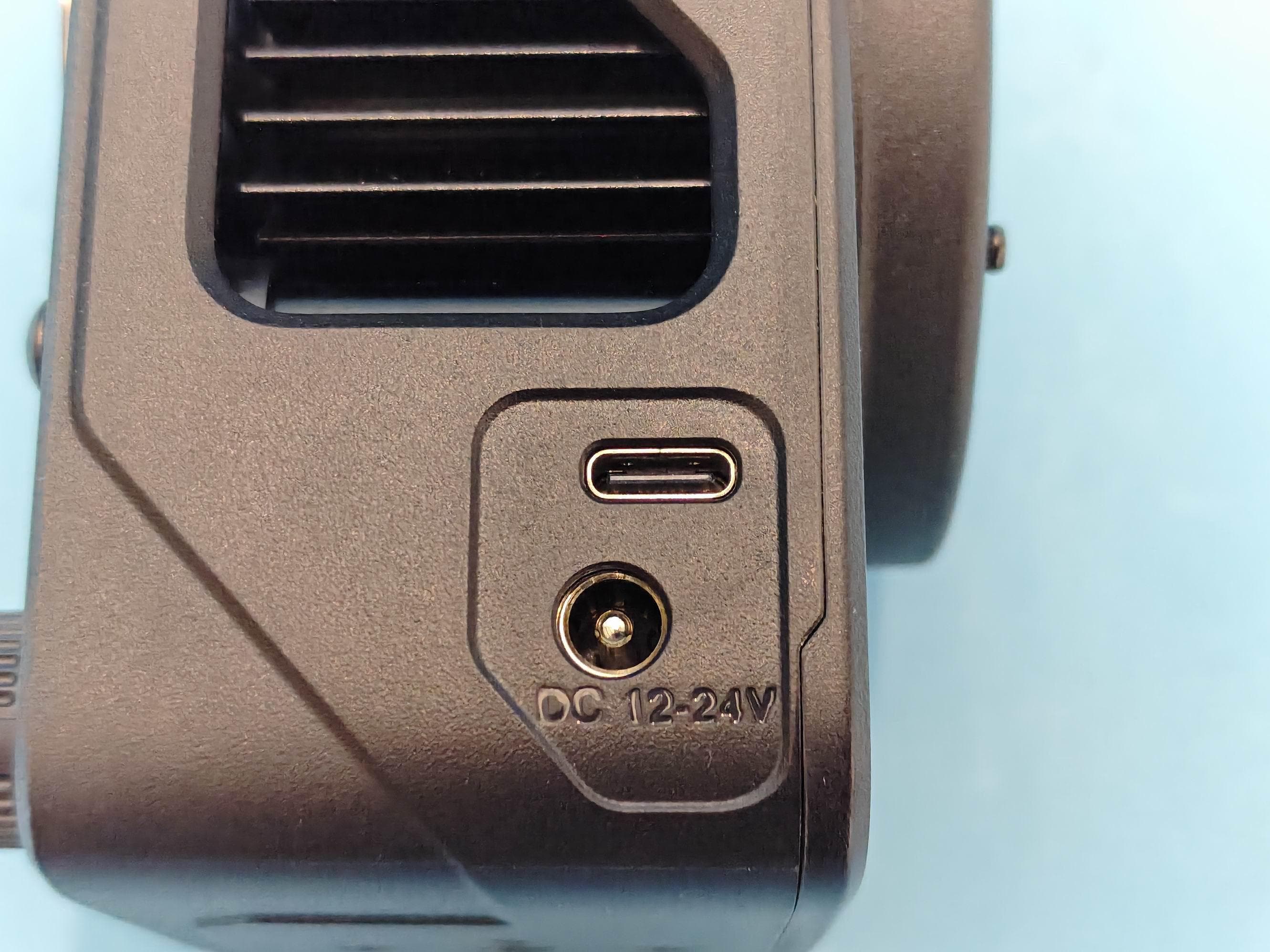
Click to zoom
Application Details
- Equipment Class
- DTS - Digital Transmission System
- Date of Grant
- Jun 22, 2026
- Application Purpose
- Original Equipment
- Equipment Note
- Compact 150W Monolight
- Frequency Range
- 2402.00000000 - 2480.00000000
- Company
- Gradus Group
- Country
- United States
Documents & Files
Document Text
Text extracted from the exhibit documents filed with the FCC. Open a document above to read the original.
Users Manual
USER MANUAL Compact 150 Watt LED MONOLIGHT 150W-BI-K1 / 150W-RGB-K1 150W-xxx-K1_Manual.indd 1150W-xxx-K1_Manual.indd 15/7/26 5:05 PM5/7/26 5:05 PM Compact 150 Watt LED Monolight - USER MANUAL 2 Compact 150 Watt LED Monolight - USER MANUAL 3 THANK YOU FOR CHOOSING GENARAY The Genaray 150-watt Monolight Kit features a compact and powerful LED light that has enough power output to light subjects from a distance without interfering with the picture frame. Ideal for image makers on the go, its compact form factor and included rechargeable battery handle make it road ready and dependable whenever you need to light subjects or scenes. Onboard and wireless control via the LEDLYD app make the 150W-BI-K1 and 150W-RGB-K1 great choices as stand-alone lights in the field or in a multi-light setup. The monolight kit includes all the tools needed for lighting vlogs, interviews, and a host of other uses. The handle features a 77 Wh rechargeable battery that has enough power to light quick news videos out in the field. For longer photo and video sessions, the light can be powered directly via the included AC adapter. The kit includes a textured silver reflector for directing your light while preventing light spill and amplifying the beam. · Please read and follow these instructions and keep this manual in a safe place. · Clean the unit with only a soft, dry cloth. · Use only parts provided by the manufacturer. · Make sure that this product is intact and that there are no missing parts. · Keep this unit away from water and any flammable gases or liquids. · Use only the correct, recommended voltage. · Do not attempt to disassemble or repair the equipment—doing so will void the warranty, and Genaray will not be responsible for any damage. · The high-intensity LEDs emit a bright light. Never stare directly into the light. · Disconnect all cables prior to transport. · All images are for illustrative purposes only. PRECAUTIONS Precautions Compact 150 Watt LED Monolight INTRODUCTION 150W-xxx-K1_Manual.indd 2-3150W-xxx-K1_Manual.indd 2-35/7/26 5:05 PM5/7/26 5:05 PM Compact 150 Watt LED Monolight - USER MANUAL 4 Compact 150 Watt LED Monolight - USER MANUAL 5 Product o verview PRODUCT OVERVIEW FrontBattery HandleTilt AdapterBack Diffuser (RGB light only) Reflector Mini Bowens mount DC 12.24 V barrel connector USB-C port Heat sink Reflector release button DIM knob LCD screen Power switch SET knob / Cursor 1/4-20 mounting stud Guide pins Locking wheel Tilt lock USB-C port (input and output) DC barrel connector (output only) Battery indicator LEDs and battery check button 1/4-20 mounting socket 1/4-20 mounting screw Quick release plate Quick release lock Umbrella lock Tilt lock Locking knob 5/8 in. baby receiver 150W-xxx-K1_Manual.indd 4-5150W-xxx-K1_Manual.indd 4-55/7/26 5:05 PM5/7/26 5:05 PM Compact 150 Watt LED Monolight - USER MANUAL 6 Compact 150 Watt LED Monolight - USER MANUAL 7 ATTACHING THE HANDLE Align the handle’s guide pins with the light’s guide holes. Attach the light by turning the locking wheel counterclockwise until secure. For mounting lights that don’t have guide pins, place the included rubber spacer over the mounting plate. This forms a flat surface for mounting a light with a 1/4-20 mounting socket. The light includes an integrated mini Bowens mount reflector with a textured silver interior that directs and amplifies the beam. To attach the included reflector: 1. Insert the reflector’s mounting pegs into the accessory slots on the front of the light. 2. Turn the reflector clockwise until it clicks. ATTACHING THE REFLECTOR To remove the reflector, slide the reflector release button backward, turn the reflector counterclockwise, and remove it from the mount. MOUNTING THE LIGHT Screw the handle onto a tripod’s or light stand’s 1/4-20 mounting stud until secure. The light can also be mounted directly onto a tripod or stud with a 1/4-20 top stud. instructions instructions 150W-xxx-K1_Manual.indd 6-7150W-xxx-K1_Manual.indd 6-75/7/26 5:05 PM5/7/26 5:05 PM Compact 150 Watt LED Monolight - USER MANUAL 8 Compact 150 Watt LED Monolight - USER MANUAL 9 ADJUSTING THE TILT USING THE TILT ADAPTER Important! Always hold the light with one hand when adjusting the tilt angle. Turn the tilt lock counterclockwise to loosen the tilt adapter. Adjust the tilt angle and retighten the tilt lock. The tilt adapter is compatible with any light stand or wall mount with a 5/8-inch baby pin stud. Attach the light to the tilt adapter for light stand mounting. Without the handle, the light must run on AC power. To mount the light to the tilt adapter: 1. Loosen the locking knob and place the receiver onto the mounting stud until it’s completely inserted. Tighten the locking knob until secure. 2. Press the quick release lock to remove the quick release plate from the adapter and attach it to the base of the light. 3. Angle the quick-release plate into lock side of the clamp and press down on the opposite side until the plate snaps into place. The tilt adapter has a +90° to -90° range and is secured by a rosette joint that won’t slip once the light angle is set. Loosen the tilt lock, adjust the angle, and retighten the tilt lock until secure. Use an umbrella to soften and diffuse the light and eliminate hot spots. Slide the handle into the umbrella mount and tighten the umbrella lock until secure. instructions instructions 150W-xxx-K1_Manual.indd 8-9150W-xxx-K1_Manual.indd 8-95/7/26 5:05 PM5/7/26 5:05 PM Compact 150 Watt LED Monolight - USER MANUAL 10 Compact 150 Watt LED Monolight - USER MANUAL 11 CONNECTING THE LIGHT TO A POWER SOURCE Option 1: Connect the light to the handle with the included barrel connector power cord. Option 2: Connect the light to the handle with the included USB-C cable. Press the battery check button and then turn on the light. CHARGING THE HANDLE The handle houses a Li-ion battery that can be recharged via the USB-C port with a wall charger or power bank. Press the battery check button to see the handle’…
Text truncated - open the document above for the full version.
Attestation Statements
Gradus Group Address: 370 West 35th Street New York, NY 10001 Date: 2026-06-01 Federal Communications Commission Authorization and Evaluation Division 7435 Oakland Mills Road Columbia, MD 21046 Ref: Attestation Statements Part 2.911(d)(7) Filing SUBJECT: FCC Application for FCC ID: 2ACZK-150W-BI-K1 FRN:0023872500 (“Gradus Group”) certifies that, as of the date of the filing of the application, Gradus Group is our designated U.S. agent for service of process for the above referenced FCC ID. (“Gradus Group”) accepts to maintain an agent for no less than one year after the grantee has terminated all marketing and importation or the conclusion of any Commission-related proceeding involving the equipment. Gradus Group accepts, as of the date of the filing of the application, the obligation of the designated U.S. agent for service of process for the above referenced FCC ID. Designated U.S. Agent Information: Name: Gradus Group Address: 370 West 35th Street New York, NY 10001 FRN: 0023872500 Contact Person : Israel Brody Te l : 212-594-2120 Email: [email protected] Sincerely, Signed on behalf of (Gradus Group) Signed on behalf of Gradus Group Name: Israel Brody Name: Israel Brody Title: Manager Title: Manager Date: 2026-06-01 Date: 2026-06-01 Israel Brody Israel Brody
External Photos
Page 1 of 4FCC ID: 2ACZK-150W-BI-K1 Dongguan Yaxu (AiT) Technology Limited No. 22, Jinqianling 3rd Street, Jitigang, Huangjiang, Dongguan,Guangdong, China External Photos Photo 1 Photo 2 Page 2 of 4FCC ID: 2ACZK-150W-BI-K1 Dongguan Yaxu (AiT) Technology Limited No. 22, Jinqianling 3rd Street, Jitigang, Huangjiang, Dongguan,Guangdong, China Photo 3 Photo 4 Page 3 of 4FCC ID: 2ACZK-150W-BI-K1 Dongguan Yaxu (AiT) Technology Limited No. 22, Jinqianling 3rd Street, Jitigang, Huangjiang, Dongguan,Guangdong, China Photo 5 Photo 6 Page 4 of 4FCC ID: 2ACZK-150W-BI-K1 Dongguan Yaxu (AiT) Technology Limited No. 22, Jinqianling 3rd Street, Jitigang, Huangjiang, Dongguan,Guangdong, China Photo 7 Photo 8 ------End------
ID Label/Location Info
Label FCCID:2ACZK-150W-BI-K1
Internal Photos
Page 1 of 7FCC ID: 2ACZK-150W-BI-K1 Dongguan Yaxu (AiT) Technology Limited No. 22, Jinqianling 3rd Street, Jitigang, Huangjiang, Dongguan,Guangdong, China Internal Photos Photo 1 Photo 2 Page 2 of 7FCC ID: 2ACZK-150W-BI-K1 Dongguan Yaxu (AiT) Technology Limited No. 22, Jinqianling 3rd Street, Jitigang, Huangjiang, Dongguan,Guangdong, China Photo 3 Photo 4 Page 3 of 7FCC ID: 2ACZK-150W-BI-K1 Dongguan Yaxu (AiT) Technology Limited No. 22, Jinqianling 3rd Street, Jitigang, Huangjiang, Dongguan,Guangdong, China Photo 5 Photo 6 Page 4 of 7FCC ID: 2ACZK-150W-BI-K1 Dongguan Yaxu (AiT) Technology Limited No. 22, Jinqianling 3rd Street, Jitigang, Huangjiang, Dongguan,Guangdong, China Photo 7 Photo 8 Page 5 of 7FCC ID: 2ACZK-150W-BI-K1 Dongguan Yaxu (AiT) Technology Limited No. 22, Jinqianling 3rd Street, Jitigang, Huangjiang, Dongguan,Guangdong, China Photo 9 Photo 10 Page 6 of 7FCC ID: 2ACZK-150W-BI-K1 Dongguan Yaxu (AiT) Technology Limited No. 22, Jinqianling 3rd Street, Jitigang, Huangjiang, Dongguan,Guangdong, China Photo 11 Photo 12 Page 7 of 7FCC ID: 2ACZK-150W-BI-K1 Dongguan Yaxu (AiT) Technology Limited No. 22, Jinqianling 3rd Street, Jitigang, Huangjiang, Dongguan,Guangdong, China Photo 13 ------End------ BT Antenna
RF Exposure Info
Page1of8ReportNo.:AiTDG-260422002W2 Note:Thisdevicehasbeentestedandfoundtocomplywiththestandard(s)listed,thistestreportmerelycorrespondstothe testsample.Itisnotpermittedtocopyextractsofthesetestresultwithoutthewrittenpermissionofthetestlaboratory.This reportshallnotbereproducedexceptinfull,withoutthewrittenapprovalofDongguanYaxu(AiT)TechnologyLimited.Ifthere isaneedtoalterorrevisethisdocument,therightbelongstoDongguanYaxu(AiT)TechnologyLimited,anditshouldgivea priorwrittennoticeoftherevisiondocument.Thistestreportmustnotbeusedbytheclienttoclaimproductendorsement. DongguanYaxu(AiT)TechnologyLimited No.22,Jinqianling3rdStreet,Jitigang,Huangjiang,Dongguan,Guangdong,China. RFExposureevaluation ProductName: Compact150WMonolight BrandName: Genaray Model: 150W-BI-K1 SeriesModel: 150W-RGB-K1 FCCID:2ACZK-150W-BI-K1 Applicant: GradusGroup Address: 370West35thStreet,NewYork,NY10001,UnitedStates Manufacturer: JiangmenLiyadiPhotographyEquipmentCo.,Ltd. Address: 9thFloor,BuildingB,No.83,YunqinRoad,JianghaiDistrict, JiangmenCity,GuangdongProvince,China Standard(s): 47CFR§1.1310,47CFR§2.1091 KDB447498D01GeneralRFExposureGuidancev06 DateofReceipt:Apr.22,2026 DateofTest:Apr.22,2026~May.11,2026 IssuedDate:May.12,2026 IssuedBy: DongguanYaxu(AiT)TechnologyLimited No.22,Jinqianling3rdStreet,Jitigang,Huangjiang,Dongguan,Guangdong,China Tel.:+86-769-82020499Fax.:+86-769-82020495 Reviewedby:Approvedby: EmiyaLinSimbaHuang Page 2 of 8 ReportNo.:AiTDG-260422002W2 ReportReviseRecord ReportVersionIssuedDateNotes M0May.12,2026InitialRelease Page 3 of 8 ReportNo.:AiTDG-260422002W2 Contents 1GENERALINFORMATION.............................................................................................................................................4 1.1ENVIRONMENTALCONDITIONS........................................................................................................................................4 1.2GENERALDESCRIPTIONOFEUT......................................................................................................................................4 1.3TESTFACILITY...............................................................................................................................................................5 1.4MEASUREMENTUNCERTAINTY........................................................................................................................................6 2METHODOFMEASUREMENT......................................................................................................................................7 2.1APPLICABLESTANDARD.................................................................................................................................................7 2.2LIMIT..........................................................................................................................................................................7 2.3MPECALCULATIONMETHOD.........................................................................................................................................8 2.4MANUFACTURINGTOLERANCE........................................................................................................................................8 2.5STANDALONEMPERESULT............................................................................................................................................8 2.6CONCLUSION................................................................................................................................................................8 Page 4 of 8 ReportNo.:AiTDG-260422002W2 1GENERALINFORMATION 1.1Environmentalconditions Duringthemeasurementtheenvironmentalconditionswerewithinthelistedranges: NormalTemperature:25°C RelativeHumidity:55% AirPressure:101kPa 1.2GeneralDescriptionofEUT ProductName:Compact150WMonolight Model/Type reference: 150W-BI-K1 SerialModel:150W-RGB-K1 Powersupply:12~24VDC ADAPTOR: ModelNo:JYH11Z-2400625-BF Input:100-240V~50/60Hz2.7A Output:24.0V6.25A150.0W Hardwareversion.:N/A Softwareversion.:N/A Testsample(s)ID:AiTDG-260422002-1 BT: Operationfrequency:2402MHz-2480MHz ChannelNumber:40channels Channelseparation:2MHz Modulation Technology: GFSK AntennaType:PCBAntenna Antennagain:3.3dBi Remark:TheaboveDUT'sinformationwasdeclaredbymanufacturer.Formoredetailedfeatures description,pleaserefertothemanufacturer’sspecificationsortheUser'sManual. Page 5 of 8 ReportNo.:AiTDG-260422002W2 1.3TestFacility TestLaboratory: DongguanYaxu(AiT)TechnologyLimited No.22,Jinqianling3rdStreet,Jitigang,Huangjiang,Dongguan,Guangdong,China Thetestfacilityisrecognized,certifiedoraccreditedbythefollowingorganizations: CNAS-RegistrationNo:L6177 DongguanYaxu(AiT)technologyLimitedisaccreditedtoISO/IEC17025:2017generalRequirements forthecompetenceoftestingandcalibrationlaboratories(CNAS-CL01AccreditationCriteriaforthe competenceoftestingandcalibrationlaboratories)onApril18,2022 FCC-RegistrationNo.:362653DesignationNumber:CN1457 DongguanYaxu(AiT)technologyLimitedhasbeenregisteredandfullydescribedinareportfiledwith the(FCC)FederalCommunicationsCommission.TheacceptanceletterfromtheFCCismaintainedin ourfiles. IC-RegistrationNo.:6819CABidentifier:CN0122 The3mSemi-anechoicchamberofDongguanYaxu(AiT)technologyLimitedhasbeenregisteredby CertificationandEngineeringBureauofIndustryCanadaforradioequipmenttestingwithRegistration No.:6819A A2LA-LabCert.No.:6317.01 DongguanYaxu(AiT)technologyLimitedhasbeenaccreditedbyA2LAfortechnicalcompetencein thefieldofelectricaltesting,andprovedtobeincompliancewithISO/IEC17025:2017General RequirementsfortheCompetenceofTestingandCalibrationLaboratoriesandanyadditionalprogram requirementsintheidentifiedfieldoftesting. Page 6 of 8 ReportNo.:AiTDG-260422002W2 1.4Measurementuncertainty Thedataandresultsreferencedinthisdocumentaretrueandaccurate.Thereaderiscautionedthat theremaybeerrorswithinthecalibrationlimitsoftheequipmentandfacilities.Themeasurement uncertaintywascalculatedforallmeasurementslistedinthis…
Text truncated - open the document above for the full version.
Test Report
Page1of27ReportNo.:AiTDG-260422002W1 Note:Thisdevicehasbeentestedandfoundtocomplywiththestandard(s)listed,thistestreportmerelycorrespondstothe testsample.Itisnotpermittedtocopyextractsofthesetestresultwithoutthewrittenpermissionofthetestlaboratory.This reportshallnotbereproducedexceptinfull,withoutthewrittenapprovalofDongguanYaxu(AiT)TechnologyLimited.Ifthere isaneedtoalterorrevisethisdocument,therightbelongstoDongguanYaxu(AiT)TechnologyLimited,anditshouldgivea priorwrittennoticeoftherevisiondocument.Thistestreportmustnotbeusedbytheclienttoclaimproductendorsement. DongguanYaxu(AiT)TechnologyLimited No.22,Jinqianling3rdStreet,Jitigang,Huangjiang,Dongguan,Guangdong,China. TESTREPORT ProductName:Compact150WMonolight BrandName:Genaray Model: 150W-BI-K1 SeriesModel: 150W-RGB-K1 FCCID:2ACZK-150W-BI-K1 Applicant: GradusGroup Address: 370West35thStreet,NewYork,NY10001,UnitedStates Manufacturer: JiangmenLiyadiPhotographyEquipmentCo.,Ltd. Address: 9thFloor,BuildingB,No.83,YunqinRoad,JianghaiDistrict, JiangmenCity,GuangdongProvince,China Standard(s):FCCCFRTitle47Part15SubpartCSection15.247 DateofReceipt:Apr.22,2026 DateofTest:Apr.22,2026~May.11,2026 IssuedDate:May.12,2026 IssuedBy: DongguanYaxu(AiT)TechnologyLimited No.22,Jinqianling3rdStreet,Jitigang,Huangjiang,Dongguan,Guangdong,China Tel.:+86-769-82020499Fax.:+86-769-82020495 Reviewedby:Approvedby: EmiyaLinSimbaHuang Page 2 of 27 ReportNo.:AiTDG-260422002W1 ReportReviseRecord ReportVersionIssuedDateNotes M0May.12,2026InitialRelease Page 3 of 27 ReportNo.:AiTDG-260422002W1 Contents 1TESTSUMMARY..........................................................................................................................................................4 1.1TESTSTANDARDS..........................................................................................................................................................4 1.2TESTSUMMARY...........................................................................................................................................................4 1.3TESTFACILITY...............................................................................................................................................................5 1.4MEASUREMENTUNCERTAINTY........................................................................................................................................6 2GENERALINFORMATION.............................................................................................................................................7 2.1ENVIRONMENTALCONDITIONS........................................................................................................................................7 2.2GENERALDESCRIPTIONOFEUT......................................................................................................................................7 2.3DESCRIPTIONOFTESTMODESANDTESTFREQUENCY........................................................................................................8 2.4SPECIALACCESSORIES....................................................................................................................................................9 2.5EQUIPMENTLISTFORTHETEST......................................................................................................................................9 3TESTCONDITIONSANDRESULTS...............................................................................................................................11 3.1CONDUCTEDEMISSIONSTEST.......................................................................................................................................11 3.2RADIATEDEMISSIONSANDBANDEDGE.........................................................................................................................14 3.3MAXIMUMPEAKCONDUCTEDOUTPUTPOWER.............................................................................................................21 3.4POWERSPECTRALDENSITY..........................................................................................................................................22 3.56DBBANDWIDTH.......................................................................................................................................................23 3.6OUT-OF-BANDEMISSIONS...........................................................................................................................................24 3.7ANTENNAREQUIREMENT.............................................................................................................................................26 4TESTSETUPPHOTOGRAPHSOFEUT..........................................................................................................................27 5PHOTOSOFEUT........................................................................................................................................................27 Page 4 of 27 ReportNo.:AiTDG-260422002W1 1TESTSUMMARY 1.1TestStandards Thetestswereperformedaccordingtofollowingstandards: FCCRulesPart15.247:FrequencyHopping,DirectSpreadSpectrumandHybridSystemsthatarein operationwithinthebandsof902-928MHz,2400-2483.5MHz,and5725-5850MHz ANSIC63.10:2020:AmericanNationalStandardforTestingUnlicensedWirelessDevices KDB558074D0115.247MeasGuidancev05r02:GuidanceforComplianceMeasurementsonDigital TransmissionSystem,FrequencyHoppingSpredaSpectrumSystem,andHybridSystemDevices OperatingUnderSection15.247oftheFCCRules 1.2TestSummary TestItemSectionin47CFRResult Antennarequirement§15.203Pass OnTimeandDutyCycle// ACPowerLineConductedEmission§15.207(a)Pass ConductedPeakOutputPower§15.247(b)(3)Pass ChannelBandwidth§15.247(a)(2)Pass PowerSpectralDensity§15.247(e)Pass TransmitterRadiatedSpurious Emission §15.205/15.209Pass RestrictedBands§15.205/15.209Pass ConductedUnwantedemissionsand Bandedge §15.205,§15.247(d)Pass Page 5 of 27 ReportNo.:AiTDG-260422002W1 1.3TestFacility TestLaboratory: DongguanYax…
Text truncated - open the document above for the full version.
Test Report
Application Report 2.4-GHz Inverted F Antenna ABSTRACT This document describes a printed-circuit board (PCB) antenna design that can be used with all 2.4-GHz transceivers and transmitters from Texas Instruments ™ . The maximum gain when used on the reference board is measured to be +3.3 dBi, and the overall size requirements for this antenna are 25.7 × 7.5 mm (not including ground plane). Table of Contents 1 Description of the antenna Design........................................................................................................................................2 2 Measurement Results.............................................................................................................................................................3 2.1 Radiation Pattern...............................................................................................................................................................3 2.2 Reflection.........................................................................................................................................................................10 2.3 Bandwidth.........................................................................................................................................................................11 3 Summary................................................................................................................................................................................11 4 References.............................................................................................................................................................................11 5 Revision History...................................................................................................................................................................12 Trademarks Texas Instruments ™ is a trademark of Texas Instruments. All trademarks are the property of their respective owners. www.ti.comTable of Contents SWRU120D – APRIL 2007 – REVISED JANUARY 2019 Submit Document Feedback 2.4-GHz Inverted F Antenna1 Copyright © 2021 Texas Instruments Incorporated 1 Description of the antenna Design It is important to make an exact copy of the antenna dimensions to obtain optimum performance. The easiest approach to implement the antenna in a PCB CAD tool is to import the antenna layout from a gerber file or a DXF file. Such files are included in CC2430DB reference design [1]. The gerber file is called Inverted_F_Antenna.spl and the DXF file is called Inverted_F_Antenna.dxf. If the antenna is implemented on a PCB that is wider than the antenna, avoid placing components or having a ground plane close to the end points of the antenna. If the CAD tool being used does not support importing gerber or DXF files, see Figure 1-1 and Table 1-1. The antenna impedance is tuned to 50 ohm on the reference board. The impedance will however be affected by different size and shape of the ground plane, objects in the antenna nearfield such as mechanical assemblies (housing, batteries, etc.), PCB thickness, PCB material and so on. It is therefore recommended to add a pi-network close to the antenna feedpoint for impedance matching. The results presented in this document are based on an antenna implemented on a PCB with a 1-mm thickness using standard FR-4 material. Figure 1-1. IFA Dimensions Table 1-1. IFA Dimensions H15.70 mmW20.46 mm H20.74 mmL125.58 mm H31.29 mmL216.40 mm H42.21 mmL32.18 mm H50.66 mmL44.80 mm H61.21 mmL51.00 mm H70.80 mmL61.00 mm H81.80 mmL73.20 mm H90.61 mmL80.45 mm W11.21 mm Description of the antenna Designwww.ti.com 22.4-GHz Inverted F AntennaSWRU120D – APRIL 2007 – REVISED JANUARY 2019 Submit Document Feedback Copyright © 2021 Texas Instruments Incorporated 2 Measurement Results All of the results presented in this section are based on measurements performed with the CC2430DB [1] evaluation board. 2.1 Radiation Pattern Figure 2-1 shows how to relate all of the radiation patterns to the orientation of the antenna. The radiation patterns were measured with the CC2430 device programmed to 0-dBm output power. Figure 2-1. Relating Antenna to Radiation Patterns www.ti.comMeasurement Results SWRU120D – APRIL 2007 – REVISED JANUARY 2019 Submit Document Feedback 2.4-GHz Inverted F Antenna3 Copyright © 2021 Texas Instruments Incorporated Figure 2-2 shows the XY plane vertical polarization. Figure 2-2. XY Plane–Vertical Polarization Measurement Resultswww.ti.com 42.4-GHz Inverted F AntennaSWRU120D – APRIL 2007 – REVISED JANUARY 2019 Submit Document Feedback Copyright © 2021 Texas Instruments Incorporated Figure 2-3 shows the XY plane horizontal polarization. Figure 2-3. XY Plane–Horizontal Polarization www.ti.comMeasurement Results SWRU120D – APRIL 2007 – REVISED JANUARY 2019 Submit Document Feedback 2.4-GHz Inverted F Antenna5 Copyright © 2021 Texas Instruments Incorporated Figure 2-4 shows the XZ plane vertical polarization. Figure 2-4. XZ Plane–Vertical Polarization Measurement Resultswww.ti.com 62.4-GHz Inverted F AntennaSWRU120D – APRIL 2007 – REVISED JANUARY 2019 Submit Document Feedback Copyright © 2021 Texas Instruments Incorporated Figure 2-5 shows the XZ plane horizontal polarization. Figure 2-5. XZ Plane–Horizontal Polarization www.ti.comMeasurement Results SWRU120D – APRIL 2007 – REVISED JANUARY 2019 Submit Document Feedback 2.4-GHz Inverted F Antenna7 Copyright © 2021 Texas Instruments Incorporated Figure 2-6 shows the YZ plane vertical polarization. Figure 2-6. YZ Plane–Vertical Polarization Measurement Resultswww.ti.com 82.4-GHz Inverted F AntennaSWRU120D – APRIL 2007 – REVISED JANUARY 2019 Submit Document Feedback Copyright © 2021 Texas Instruments Incorporated Figure 2-7 shows the YZ plane horizontal polarization. Figure 2-7. YZ Plane–Horizontal Polarization www.ti.comMeasurement Results SWRU120D – APRIL 2007 – REVISED JANUARY 2019 Submit Document Feedback 2.4-GHz Inverted F Antenna9 Copyright © 202…
Text truncated - open the document above for the full version.
Test Report
Dongguan Yaxu (AiT) Technology Limited Report No.:AiTDG-260422002W1 FCC ID: 2ACZK-150W-BI-K1 Page 1 of 30 RF Test Data for BT (BLE) (Conducted Measurement) Product Name: Compact 150W Monolight Trade Mark: Genaray Test Model: 150W-BI-K1 Environmental Conditions Temperature: 24.6 C Relative Humidity:52.4% ATM Pressure:100.0 kPa Test Engineer:Emiya Lin Supervised by:Simba Huang Dongguan Yaxu (AiT) Technology Limited Report No.:AiTDG-260422002W1 FCC ID: 2ACZK-150W-BI-K1 Page 2 of 30 Contents Page COVER PAGE 1 Duty Cycle........................................................................................................................................................................................ 3 1.1 Test Result............................................................................................................................................................................3 1.2 Test Graphs...........................................................................................................................................................................4 2 Maximum Conducted Output Power................................................................................................................................................. 7 2.1 Test Result............................................................................................................................................................................7 2.2 Test Graphs...........................................................................................................................................................................8 3 -6dB Bandwidth...............................................................................................................................................................................11 3.1 Test Result.......................................................................................................................................................................... 11 3.2 Test Graphs.........................................................................................................................................................................12 4 Maximum Power Spectral Density Level.........................................................................................................................................15 4.1 Test Result..........................................................................................................................................................................15 4.2 Test Graphs............................................................................................................................................…
Text truncated - open the document above for the full version.
Contact Information
Applicant
Israel Brody
[email protected]Fax: 212-563-8636
Technical Contact
Test Firm
Dongguan Yaxu (AiT) Technology LimitedCoin Tang
Technical Specifications
| # | Rule Parts | Frequency Range | Power Output |
|---|---|---|---|
| 1 | 15C | 2.40 GHz - 2.48 GHz | 500.00 µW |
Other Applications from Gradus Group
2ACZK-PSL-16
Apr 26, 2015Wireless Remote Trigger
Equipment Class
DXX - Part 15 Low Power Communication Device Transmitter
2ACZK-VC500
Aug 21, 2014remote controller
Equipment Class
DXX - Part 15 Low Power Communication Device Transmitter