2AD3Q-VPES04Activ Hub
VOLFONI R&D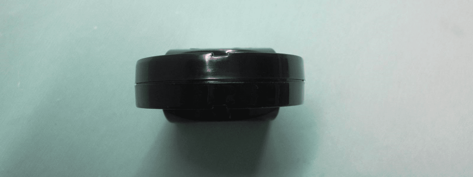
Click to zoom
Application Details
- Equipment Class
- DXX - Part 15 Low Power Communication Device Transmitter
- Date of Grant
- Apr 08, 2015
- Application Purpose
- Original Equipment
- Date of Application
- Apr 08, 2015
- Equipment Note
- Activ Hub
- Frequency Range
- 2401.50000000 - 2438.60000000
- Company
- VOLFONI R&D
- Country
- France
Documents & Files
Document Text
Text extracted from the exhibit documents filed with the FCC. Open a document above to read the original.
Users Manual
User Guide Manuel d’utilisation model VPES-04100 www.volfoni.com RF50 3 SUMMARY 1. PRODUCT OVERVIEW 4. 1.1 DESCRIPTION 4. 1.2 CONTENT OF THE ACTIVHUB TM RF50 KIT 5. 1.3 CONNECTORS AND FUNCTIONS 5. 1.4 REQUIREMENTS 5. 2. COMPATIBILITY 7. 3. USING YOUR ACTIVHUB TM RF50 8. 3.1 POWERING THE ACTIVHUB TM RF50 8. 3.2 SELECTING THE SYNCHRONIZATION SOURCE 8. 3.3 SELECTING THE EMISSION CHANNEL 9. 3.4 EXAMPLES OF SETUPS 9. 4. ADVANCED USES 12. 5. LED SIGNIFICANCES 12. 6. SOFTWARE UPDATES 13. 7. Q 13. 8. IMPORTANT SAFETY RECOMMENDATIONS 13. 9. MAINTENANCE OF THE ACTIVHUB TM RF50 14. 10. WARRANTY 14. 11. CONTACT 14. 12. REGULATORY STANDARDS 15. 4 1. PRODUCT OVERVIEW 1.1 Description The ActivHub TM RF50 is an emitter used to wirelessly synchronize 3D glasses with a 3D display system. It can receive 3D synchronization via - Wired link, typically VESA-DIN3 or BNC connectors - Infra-Red link, from a wide variety of sources like 3DTVs and 3D IR emitters - DLP-link embedded in the 3D images of a 3D-Ready TM projector It can transmit 3D synchronization via - RF link from any 3D source. - VESA Link (square signal 0-5V) Its intelligent core allows it to be - Automatically compatible with most 3D display brands using IR synchronization - Upgraded to new functions via volfoni’s website - Loaded with custom-made software for specific applications It is especially suitable for - Virtual Reality centers, thanks to its omnidirectional, interference-free RF link - Digital Content Creators, thanks to its selectable 12-channels RF Link - 3D professionals, thanks to its industry-wide multi-brand compatibility 5 1.2 Content of the ActivHub TM RF50 Kit Your ActivHub TM RF50 kit includes; - an ActivHub TM RF50 3D emitter - a VESA-DIN3 to Jack 3.5 connection cable - a BNC & USB to Jack 3.5 connection cable - a USB-A to micro-USB cable for maintenance and power 1.3 Connectors and Functions 1. USB connector 2. Jack 3.5 connector 3. IR reception window 4. DLP-Link TM reception window 5. Function selector 6. Power and Function LED 1.4 Requirements The ActivHub TM RF50 is a 3D signal emitter to be used with active glasses to view 3D contents played on an active 3D display like 3D monitors, 3DTV or 3D projectors. The ActivHub TM RF50 should receive the 3D synchronization signal from an Infrared source, a DLP-link TM compatible 3D projector, or a VESA-DIN3 or BNC connector. It can transmit the 3D signal RF, in the following configurations. 1. 6. 4. 3. 5. 2. 6 The ActivHub TM RF50 can transmit RF synchronization when connected to a VESA or BNC cable The ActivHub TM RF50 can transmit RF synchronization when receiving an IR 3D signal. The ActivHub TM RF50 can transmit RF synchronization when receiving a DLP-Link 3D signal. For complex installation please contact Volfoni technical support, [email protected] 3D Content Movie, sports... Active 3D display RF glasses ActivHUB 3D Player Computer, Blu-Ray... In=Wire, Out=RF 3D Content Movie, sports... RF glasses ActivHUB In=DLP, Out=RF 3D Content Movie, sports... Active 3D display RF glasses ActivHUB 3D Player Computer, Blu-Ray... In=Wire, Out=RF 7 2. COMPATIBILITY Active 3D TV brands compatible with ActivHub TM RF50 in IR mode : Sony®, Panasonic®, LG®, Samsung®, Konka®, Hinsen®, Arcelik®. Computer 3D displays and systems compatible with ActivHub TM RF50 in IR mode : Nvidia®, NuVision®, Volfoni®.This includes selected ACER® and ASUS® 3D monitors and laptops Your ActivHub TM RF50 uses Volfoni’s proprietary RF 3D mode. The ActivHub TM RF50 is not compatible with 3D systems using Bluetooth®, RF4CE or ZigBee RF protocols, like the Samsung® Bluetooth® Displays and Glasses, or the BitCaldron® RF Products Using your ActivHub TM RF50 in DLP-Link 3D mode The ActivHub TM RF50 is compatible with all 3D-Ready TM projectors with an active DLP-link function. The DLP-link 3D signal is an invisible light pulse embedded into the 3D image projection. Refers to your projector user manual regarding the procedure to activate the DLP-link signal. Most DLP-based rear-projection 3DTV sold after 2005 are DLP-link compatible. Compatible 3D Glasses The ActibHub TM RF50 is compatible with Volfoni 3D glasses. The ActivHub TM RF50 is specifically adapted to Volfoni 3D glasses. You may find more information about this glasses on our website www.volfoni.com. 8 Using seemingly compatible, yet non-Volfoni, glasses with the ActivHub TM RF50 will most likely generate timing issues and degrade the 3D image quality, color fidelity, sharpness and brightness. This may cause unwanted eyestrain or fatigue. These compatibility lists are indicatives. Due to possible changes of protocol by manufacturers, Volfoni cannot warranty compatibility with products previously cited 3. Using your ActivHub TM RF50 3.1 Powering the ActivHub TM RF50 The ActivHub TM RF50 gets its power either from the Jack or micro-USB ports. Do not plug both inputs to power-providing devices at once, this may damage the ActivHub TM or the host systems. The VESA port should be powered with either 5v or 12v. If your VESA is not powered, then the ActivHub TM RF50 can be powered via its USB port. In this case, make sure to use an optional universal adapter rather than a powered USB port on an electronic device. 3.2 Selecting the synchronization source Synchronization source selection is automatic on the ActivHub TM RF50. At power-on, synchronization sources like VESA, DLP-Link TM and IR, are automatically checked by the ActivHub TM . As soon as any of these three signals is detected, the ActivHub TM will focus exclusively on it until its next full power cycle. To switch to another synchronization source, you need to power off the ActivHub TM RF50. 9 The scan priority order is : 1.Wired 3D signal 2.DLP-link 3D signal 3.IR 3D signal 3.3 Selecting the emission channel This option is only available with EDGE TM VR and ActivEyes TM Pro The emission mode is selected by the function selector: 0 : Autotest mode 3 to E: RF channels 8 : Default RF channel F: VESA channel Plea…
Text truncated - open the document above for the full version.
Cover Letter(s)
VOLFONI R&D EURL au capital de 10.000€ 29, Rue Jean-Jacques Rousseau – 75001 Paris – France RCS Paris 513.362.129 – TVA FR 36.513.362.129 – SIRET 513.362.129.000.35 www.volfoni.com Date: 2014-08-18 Volfoni R&D 29 Rue Jean-Jacques Rousseau 75001 PARIS FRANCE Dear Sirs, Re.: Letter of Appointment This is the letter of authorization to accept our appointment of The Hong Kong Standards and Testing Centre Ltd. Mr. KC Lee as agent for VOLFONI R&D, 29 Rue Jean-Jacques Rousseau, 75001 Paris, FRANCE to sign applications before the Commission on our behalf, to make representations to you on our behalf, and to receive and exchange data between our company and the Commission in connection with Certification of the following product of VOLFONI R&D. Product name : ActivHub RF50 RF emitter Model : VPES-04100 This authorization will expire one year from the date of this letter. _________________________ Denis DANE System engineer
Cover Letter(s)
Page 1 Date : 2015-02-03 FCC ID: 2AD3Q-VPES04 To Whom It May Concern: Pursuant to Sections 0.457 and 0.459 of the Commission’s Rules, we hereby request confidential treatment of information accompanying this application as outlined below: Specifically, “VOLFONI R&D” requests that the following materials be withheld from public inspection under 47CFR 0.459 because they are confidential trade secrets and technical data which would be guarded from competitors. (1) detailed circuit schematic of unit under test (2) parts list (3) block diagram (4) Circuit Description Therefore, in accordance with 47CFR Sections 0.457 and 0.459 we request that the above listed materials, copies of which are attached here, be withheld from public inspection. Sincerely, Denis DANE System engineer VOLFONI R&D EURL au capital de 10.000€ 29, Rue Jean-Jacques Rousseau – 75001 Paris – France RCS Paris 513.362.129 – TVA FR 36.513.362.129 – SIRET 513.362.129.000.35 www.volfoni.com
External Photos
PHOTOGRAPH OF THE PRODUCT FRONT VIEW OF THE PRODUCT REAR VIEW OF THE PRODUCT PHOTOGRAPH OF THE PRODUCT LEFT VIEW OF THE PRODUCT RIGHT VIEW OF THE PRODUCT PHOTOGRAPH OF THE PRODUCT TOP VIEW OF THE PRODUCT BTTOM VIEW OF THE PRODUCT PHOTOGRAPH OF THE PRODUCT
Internal Photos
PHOTOGRAPH OF THE PRODUCT INNER CIRCUIT TOP VIEW PHOTOGRAPH OF THE PRODUCT INNER CIRCUIT BOTTOM VIEW PHOTOGRAPH OF THE PRODUCT
Test Report
STC Test Report Date: 2015-01-07 Page 1 of 28 No.: DM116520 Applicant: VOLFONI R&D 29 rue Jean Jacques Rousseau, 75001 Paris, France Manufacturer: VOLFONI R&D 29 rue Jean Jacques Rousseau, 75001 Paris, France Description of Sample(s): Submitted sample(s) said to be Product: ActivHub RF50 RF emitter Brand Name: Volfoni Model Number: VPES-04100 FCC ID: 2AD3Q-VPES04 Date Sample(s) Received: 2014-08-12 Date Tested: 2014-12-24 to 2014-12-26 Investigation Requested: Perform ElectroMagnetic Interference measurement in accordance with FCC 47CFR [Codes of Federal Regulations] Part 15: 2014 and ANSI C63.4: 2009 for FCC Certification. Conclusion(s): The submitted product COMPLIED with the requirements of Federal Communications Commission [FCC] Rules and Regulations Part 15. The tests were performed in accordance with the standards described above and on Section 2.2 in this Test Report. Remark(s): --- LONG Yun Jian, Along Authorized Signatory ElectroMagnetic Compatibility Department For and on behalf of STC (Dongguan) Company Limited STC Test Report Date: 2015-01-07 Page 2 of 28 No.: DM116520 CONTENT: Cover Page 1 of 28 Content Page 2 of 28 1.0 General Details 1.1 Equipment Under Test [EUT] Page 3 of 28 1.2 Description of EUT Operation Page 3 of 28 1.3 Date of Order Page 3 of 28 1.4 Submitted Sample Page 3 of 28 1.5 Test Duration Page 3 of 28 1.6 Country of Origin Page 3 of 28 2.0 Technical Details 2.1 Investigations Requested Page 4 of 28 2.2 Test Standards and Results Summary Page 4 of 28 3.0 Test Results 3.1 Emission Page 5-17 of 28 3.2 Bandwidth Measurement Page 18-24 of 28 Appendix A List of Measurement Equipment Page 25 of 28 Appendix B Photographs Page 26-28 of 28 STC Test Report Date: 2015-01-07 Page 3 of 28 No.: DM116520 1.0 General Details 1.1 Equipment Under Test [EUT] Description of Sample(s) Product: ActivHub RF50 RF emitter Manufacturer: VOLFONI R&D Brand Name: Volfoni Model Number: VPES-04100 Rating: 5.0Vd.c. (Powered by PC USB port) 1.2 Description of EUT Operation The Equipment Under Test (EUT) is a ActivHub RF50 RF emitter of VOLFONI R&D. The transceiver operating in the 2.4GHz ISM frequency band. The RF signal was modulated by IC, the type of modulation used is FSK. 1.3 Date of Order 2014-08-12 1.4 Submitted Sample(s): 1 Sample 1.5 Test Duration 2014-12-24 to 2014-12-26 1.6 Country of Origin China STC Test Report Date: 2015-01-07 Page 4 of 28 No.: DM116520 2.0 Technical Details 2.1 Investigations Requested Perform Electromagnetic Interference measurements in accordance with FCC 47CFR [Codes of Federal Regulations] Part 15: 2014 Regulations and ANSI C63.4:2009 for FCC Certification. 2.2 Test Standards and Results Summary Tables EMISSION Results Summary Test Condition Test Requirement Test Method Class / Test Result Severity Pass Fail N/A Field Strength of Fundamental & Harmonics Emissions FCC 47CFR 15.249 ANSI C63.4:2009 N/A Radiated Emissions FCC 47CFR 15.209 ANSI C63.4:2009 N/A AC Mains Conducted Emissions FCC 47CFR 15.207 ANSI C63.4:2009 N/A Note: N/A - Not Applicable STC Test Report Date: 2015-01-07 Page 5 of 28 No.: DM116520 3.0 Test Results 3.1 Emission 3.1.1 Radiated Emissions Test Requirement: FCC 47CFR 15.249 & FCC 47CFR 15.209 Test Method: ANSI C63.4:2009 Test Date: 2014-12-26 Mode of Operation: Communication mode Test Method: The sample was placed 0.8m above the ground plane of semi-anechoic Chamber*. Measurements in both horizontal and vertical polarities were performed. During the test, each emission was maximized by: having the EUT continuously working, investigated all operating modes, considered typical configuration to obtain worst position, manipulating interconnecting cables, rotating turntable, varying antenna height from 1m to 4m in both horizontal and vertical polarizations. The emissions worst-case are shown in Test Results of the following pages. *: Semi-anechoic chamber located on the STC (Dongguan) Company Ltd. 68 Fumin Nan Road, Dalang, Dongguan, Guangdong, PRC with a metal ground plane filed with the FCC pursuant to section 2.948 of the FCC rules, with Registration Number: 629686. STC Test Report Date: 2015-01-07 Page 6 of 28 No.: DM116520 Absorbers Spectrum Analyzer Setting: 9KHz – 30MHz (Pk & Av) RBW: 10kHz VBW: 30kHz Sweep: Auto Span: Fully capture the emissions being measured Trace: Max. hold 30MHz – 1GHz (QP) RBW: 120kHz VBW: 120kHz Sweep: Auto Span: Fully capture the emissions being measured Trace: Max. hold Above 1GHz (Pk & Av) RBW: 3MHz VBW: 3MHz Sweep: Auto Span: Fully capture the emissions being measured Trace: Max. hold Test Setup: Measurement Receiver Computer Ground Plane - Absorbers placed on top of the ground plane are for measurements above 1000MHz only. - Measurements between 30MHz to 1000MHz made with Bi-log antennas, above 1000MHz horn antennas are used, 9kHz to 30MHz loop antennas are used. Turn-table Distance = 3m Semi-Anechoic Chamber EUT STC Test Report Date: 2015-01-07 Page 7 of 28 No.: DM116520 Limits for Field Strength of Fundamental & Harmonics Emissions [FCC 47CFR 15.249]: Frequency Range of Fundamental Field Strength of Fundamental Emission Field Strength of Harmonics Emission [MHz] [microvolts/meter] [microvolts/meter] 902-928 500,000 [Quasi-Peak] 500 [Average] 2400-2483.5 50,000 [Average] 500 [Average] Results of Tx mode (Lowest Frequency Channel): Pass CorrectionLimit @3mE-Field FactorPolarity 2401.5057.636.894.452,480.7500,000Vertical MHz Field Strength Field Strength of Fundamental Emissions Peak Value FrequencyMeasured Level @3m Field Strength CorrectionLimit @3mE-Field FactorPolarity 2401.5045.936.882.713,645.850,000Vertical Field Strength of Fundamental Emissions Average Value FrequencyMeasured Level @3m Field Strength MHz Field Strength CorrectionLimit @3mE-Field FactorPolarity 4803.014.141.555.6602.65,000Vertical 4803.012.242.454.6537.05,000Horizontal 7204.510.445.155.5595.75,000Vertical 7204.59.046.255.2575.45,000Horizontal 9606.07.148.055.1568.95,000Vertical 9606.06.548.855.3582.15,000Horizontal 12007.54.251.555.7…
Text truncated - open the document above for the full version.
Test Setup Photos
PHOTOGRAPH OF THE PRODUCT MEASUREMENT OF RADIATED EMISSION TEST SET UP PHOTOGRAPH OF THE PRODUCT MEASUREMENT OF CONDUCTED EMISSION TEST SET UP
Contact Information
Applicant
Denis DANE(System Engineer)
Test Firm
The Hong Kong Standards and Testing Centre Ltd.Wilson Wong
Technical Specifications
| # | Rule Parts | Frequency Range | Power Output |
|---|---|---|---|
| 1 | 15C | 2.40 GHz - 2.44 GHz | - |
Other Applications from VOLFONI R&D

2AD3Q-VPEG05
Apr 08, 2015Virtual Reality 3D glasses
Equipment Class
DXX - Part 15 Low Power Communication Device Transmitter